Project
Objective: To carry out a system-level simulation of an all-terrain vehicle.
Theory: All-Terrain Vehicle
An all-terrain vehicle (ATV) is defined as a motorized off-highway vehicle designed to travel on four low-pressure or non-pneumatic tires, having a seat designed to be straddled by the operator and handlebars for steering control. ATVs are subdivided into two types as designated by the manufacturer. Type I ATVs are intended by the manufacturer for use by a single operator and no passenger. Type II ATVs are intended by the manufacturer for use by an operator and a passenger and are equipped with a designated seating position behind the operator. Similarly, riders must also consider the various ATV sizes.
Simulink Model:
There are 5 models (3 Simscape models and 2 including dashboard). Though the outline of the model looks the same I will explain the overall block structure used in all the models including the unique feature blocks and it's functions in the forthcoming explanation.
Case 1: Model Explanation
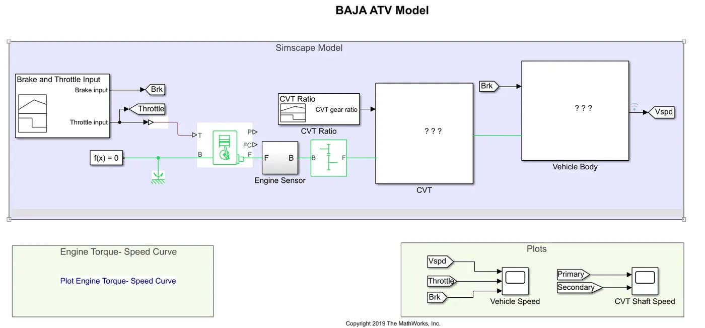
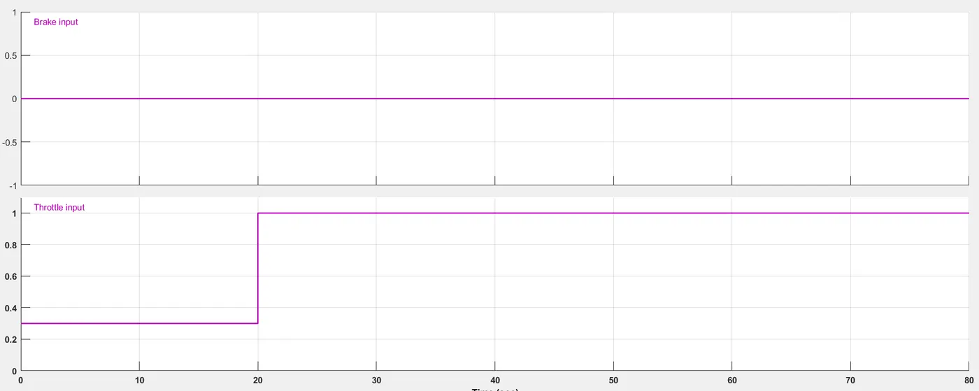
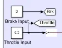
1. The below image depicts the input given for the first case, they have created 2 inputs (one for the Brake and the other one is for the Throttle), this is done using the "Signal Builder" block. 2 "Goto" blocks are also used to indicate the Brake and Throttle, this "Goto" is used in the other end of the model and as well for plotting the results as we can observe in the overall model view. Also "Simulink-PS convertor" block is used since all the inputs given are through Simulink blocks.
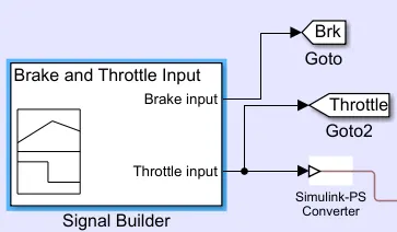
2. Here the throttle input is connected to the T input port of "Generic Engine" through the Simulink-PS convertor.
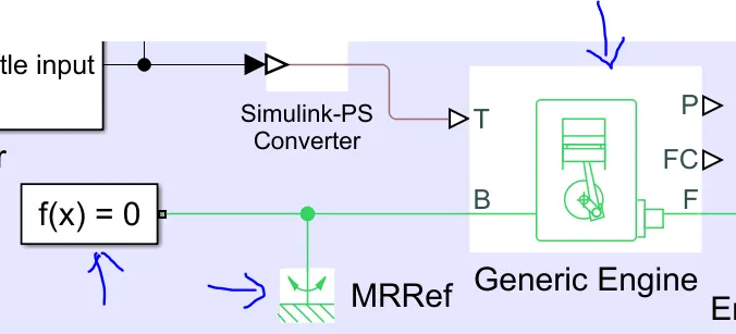
Generic Engine Block:
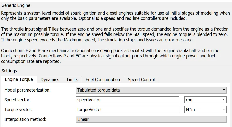
The attached picture is the Generic Engine block input area. As it indicates it is the basic model applicable for both the SI and CI engines and it also indicates that the throttle value should lie between 0 and 1, which is exactly given in the Signal Builder.
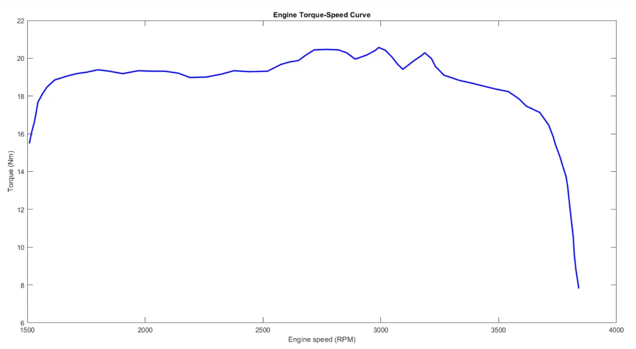
In the Engine torque section, the Model parameter is selected as "tabulated torque data", beneath that has the speed and torque vector for which the values are entered through Matlab script name. The values of that are available in the workspace.
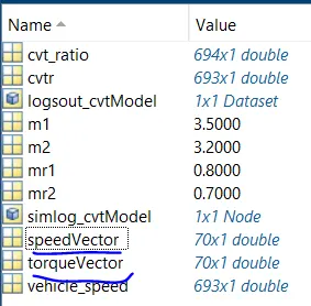
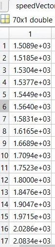
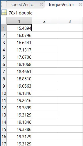
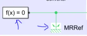
A "Solver" [f(x)=0] block is mandatorily required to begin the simulation. The "Mechanical Rotational reference" block is required for all the rotatory parts attached to the frame of the car.
3. The output F of the Engine block (which is the mechanical rotational conserving ports with the crankshaft) is connected as an input to the subsystem block as shown below,
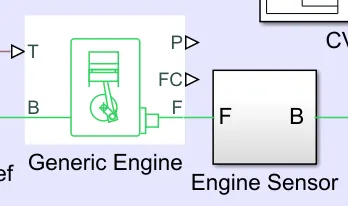
Expanding the subsystem block we get,
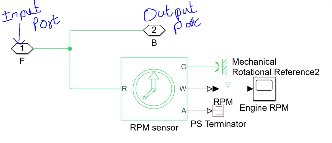
The input port is connected to the "Ideal Rotational Motion Sensor" , this helps to note down the Engine RPM. Among the 3 outputs, one is connected to the Mechanical rotational reference, Scope(before which the physical signal is converted to Simulink) and a "PS Terminator" (which actually connected to cut off the physical outputs).
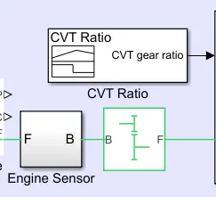
4. The output 'B' of the subsystem is connected to a "Simple gear" (which is fixed gear input, in this case, they have given it as 4)
5. Theory: CVT (Continuously Variable Transmission)
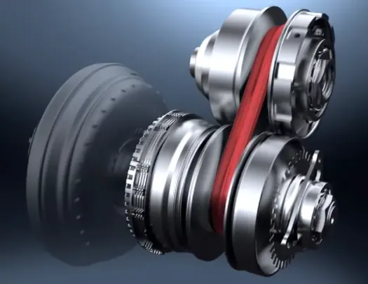
CVT stands for Continuously Variable Transmission, a type of automatic transmission that lacks a set number of gears or “speeds.” Instead, this type of automatic can vary the gear ratio infinitely between its lowest starting ratio and highest cruising ratio. Doing so allows the engine to run at its most efficient rpm for the vehicle speed, road grade or load condition that’s present at any given time. However, this makes CVT-equipped powertrains sound fundamentally different because the engine speed tends to remain steady as the transmission continuously and seamlessly alters its gearing to make the car accelerate. Those who expect or prefer a stepped series of gear changes therefore tend to dislike CVT powertrains.
Unlike Automatic Transmission, CVT does not require a Torque Converter because of the smaller steps between the adjacent gears. An infinite gear count means no steps at all, which is why CVTs are sometimes called “stepless” transmissions.
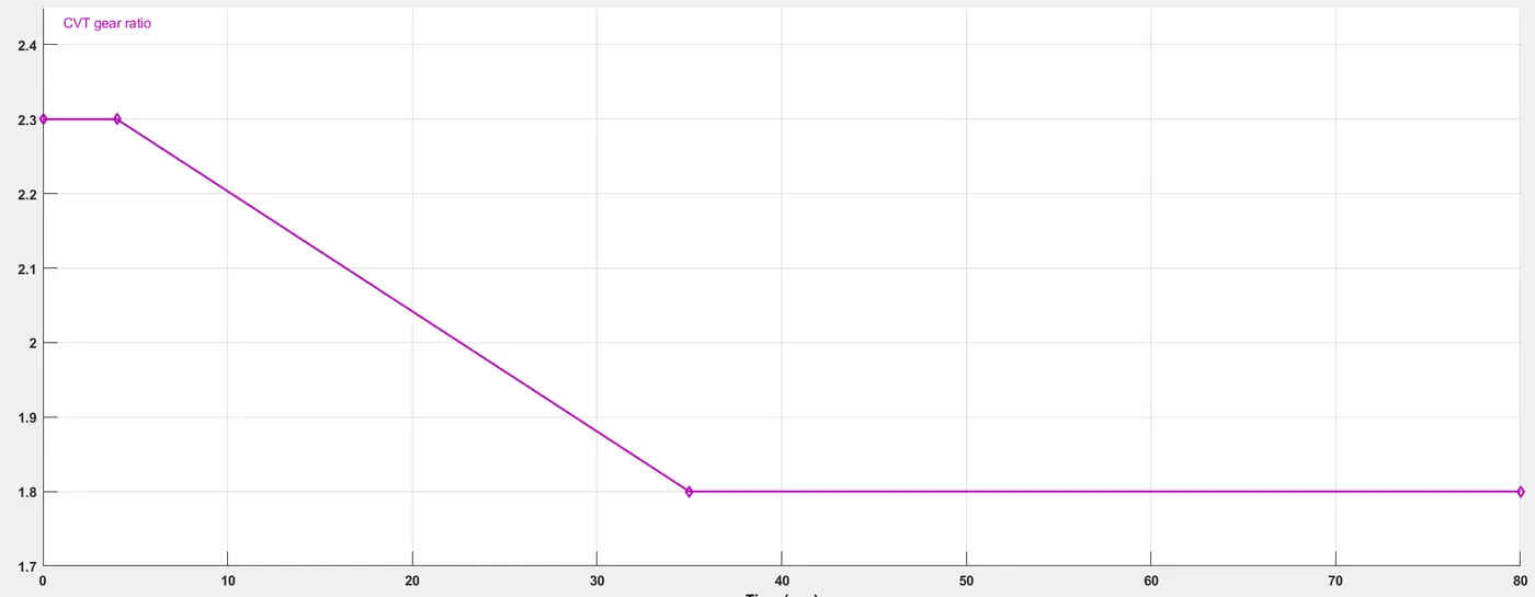
6. The CVT is fed with a gear ratio (max to min, with respect to time) through the "Signal Builder" block.
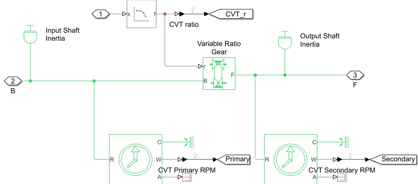
Here inside the CVT there are 2 shafts for Inertia (one for input and other for output). The input inertia shaft is connected to the "Variable Ratio Gear" (Represents a variable ratio gearbox such as implemented by mechanical belt CVT, electric, or hydraulic transmissions. The physical signal input r defines the ratio of input to output angular shaft velocities).
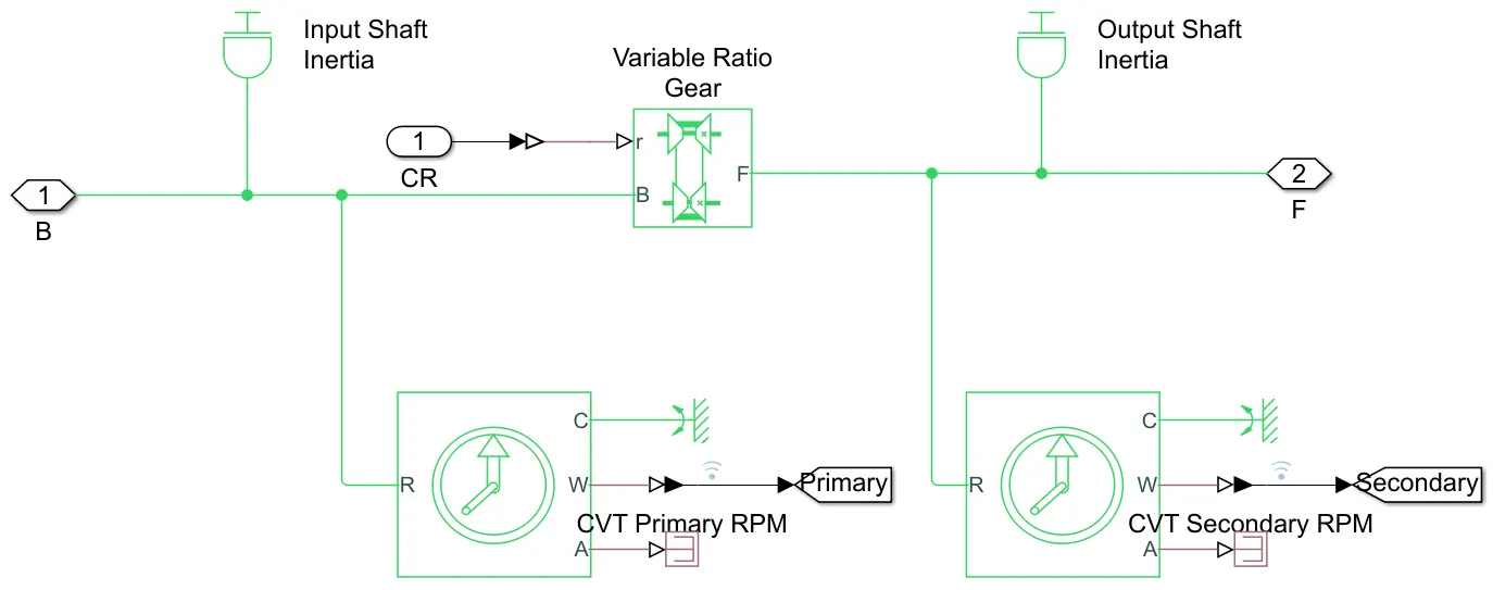
Here as well, 2 RPM sensors are connected to check the speed before and after the passing through the Variable Gear Ratio. The output from both these is collected through the "Goto" block.
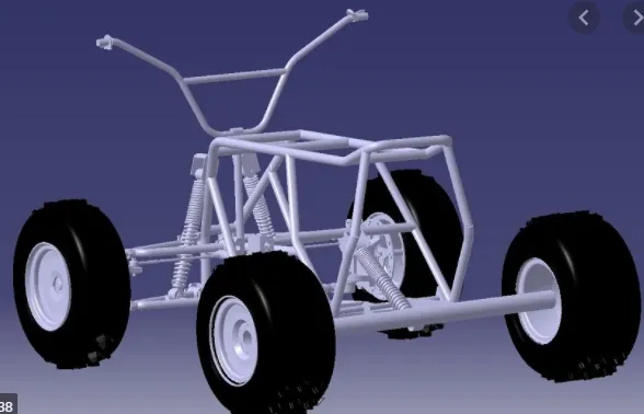
7. Vehicle Body - Usually the Vehicle Body of the ATV includes the Frame, two axles supporting 4 tires each (front and rear) and suspensions. This Vehicle Body is then subjected to drag and lift force. Traction control, Vehicle Centre of gravity, Brakes are some of the crucial parameters considered for this model.
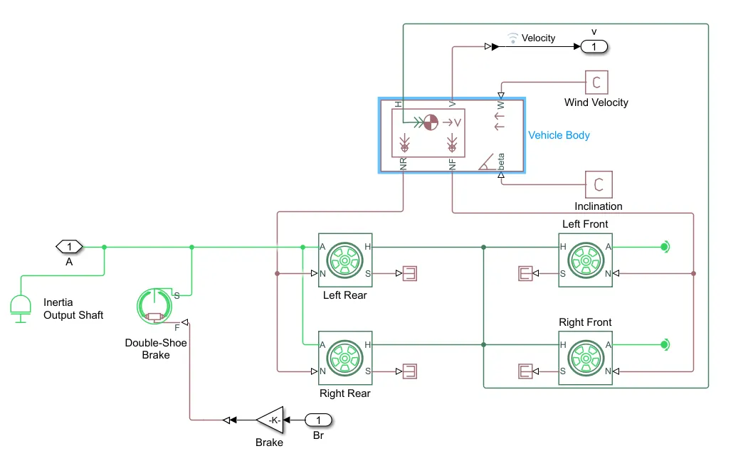
From the Input, an inertia shaft is connected to the "Double Brake shoe"(Drum Brake) Block. The other end of this block through which Force value is fed (force required for the actuators to operate the Drum brake). For this the "Gain" Block is used along with constant (Inport block).
Then comes the "Tire" Block which has 2 input and 2 output. The input A is a mechanical rotational conserving port for the wheel axle (only rear) hence it is connected to the Double shoe brake, whereas the front wheel A is connected to a rotational free end. The other input 'N' is the Normal force input from the "Vehicle Body" block.
The output 'H' is the mechanical translational conserving port for the wheel hub through which the thrust developed by the tire (It is associated with horizontal motion of the body) is applied to the vehicle to which all 4 connected to the "Vehicle Body" block.
The next is the "Vehicle Body" represents a two-axle vehicle body in longitudinal motion. The block accounts for body mass, aerodynamic drag, road incline, and weight distribution between axles due to acceleration and road profile. The vehicle can have the same or a different number of wheels on each axle. Optionally include pitch and suspension dynamics or additional variable mass and inertia. The vehicle does not move vertically relative to the ground.The output connection H and NF & NR is mentioned in the earlier discussion. Connections W and beta are physical signal input ports corresponding to headwind speed and road inclination angle, respectively.
The output "V" is connected to an outport through the PS-Simulink Convertor. They have also added "Visualize Signal" which provides a comprehensive view of your data by allowing you to group data from multiple simulations and sources on multiple subplots.
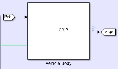
The Brake value (beacuse of the Goto Block) from the Signal builder is now given as input to the Vehicle Body block. The output of the Vehicle Body block is connected to another Goto block named "Vspd". Again here as well the Visualize Signal is provided.
Results of Case 1:
1. It is clearly witnessed the Engine Torque is more optimised and it's almost constnant with the Engine speed, this is the concept of CVT. Thereby providing better fuel efficiency.
2. The first graph depicts how the Velocity is increasing with the time and becoming constant after 40 seconds.
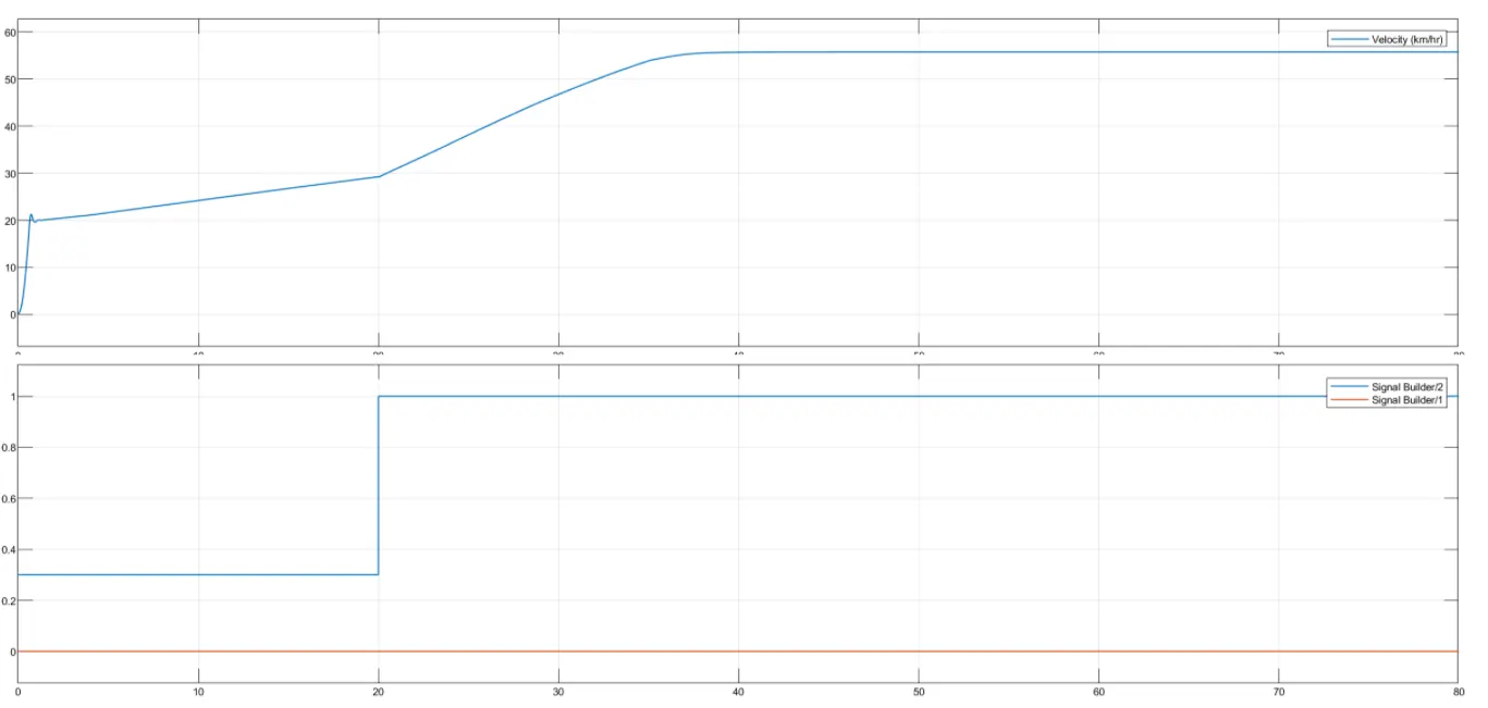
As given the input the, the throttle value is 0.3 till 20 seconds and then goes to 1 till 80 seconds. The brake is also similar to the input which is 'zero' for 80 seconds.
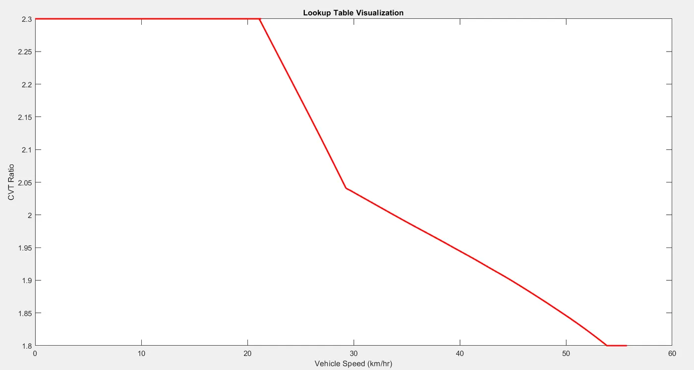
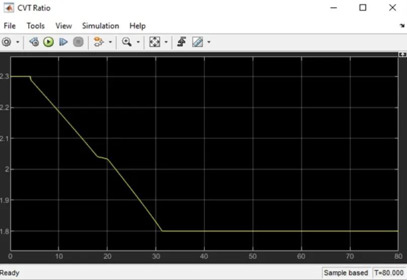
3. The below mentioned graph indicates the Gear ratio maintained in the CVT for the various speed. It is noted till 22km/hr the gear ratio is around 2.3 and it gradually decreases with the increase in the Speed and finally reaches 1.8 for the speed abobe 55km/hr.
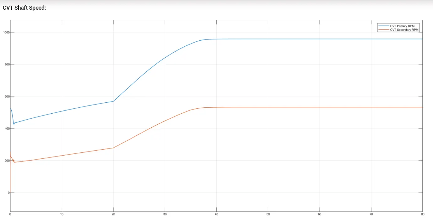
The primary is the driver RPM and the secondary is driven RPM. Beacuse of the Gear ratio Driver RPM is higher than the Driven RPM.
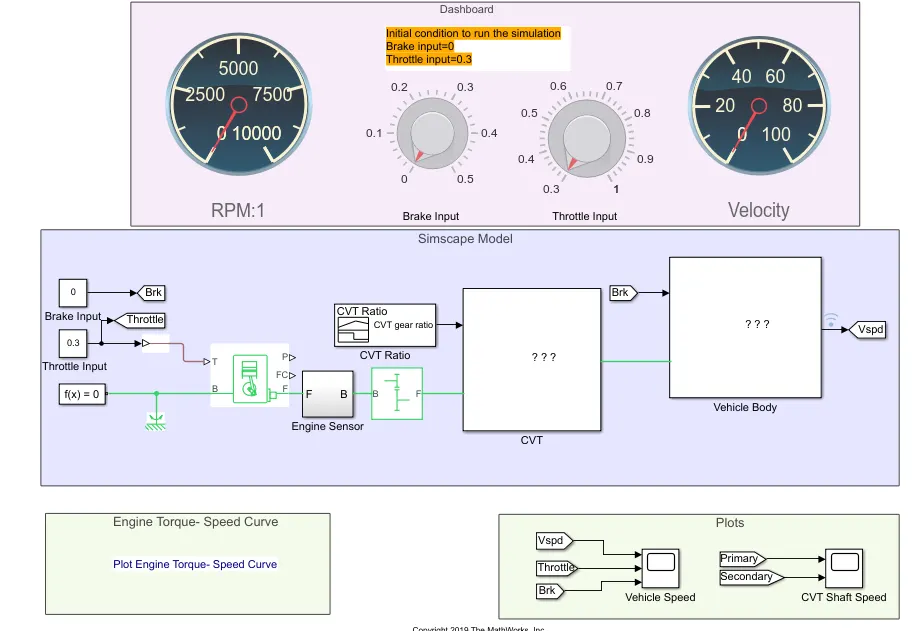
Case 2: ATV model with the Dashboard
Here the input for the Brake and Throttle is given as constant instead of the "Signal Builder" block in the previous model.
Here the unlike the previous model, both the brake input and throttle input can be varied using the knob provided in the Dashboard. This Dashboard is nothing but the Speedometer which is conventionally present in the Vehicle's Instruemental Panel.
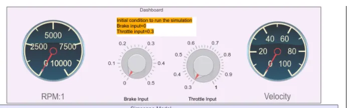
Output for the Case 2:
1. When I ran the simulation with the input condition, the maximum velocity is coming around 45 kmph which is excatly matching with plot obtained using the previous model.
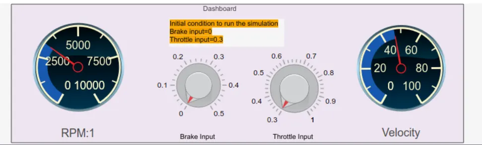
2. Below are the simualtion results for the inputs Brake = 0.2 and Throttle input = 1
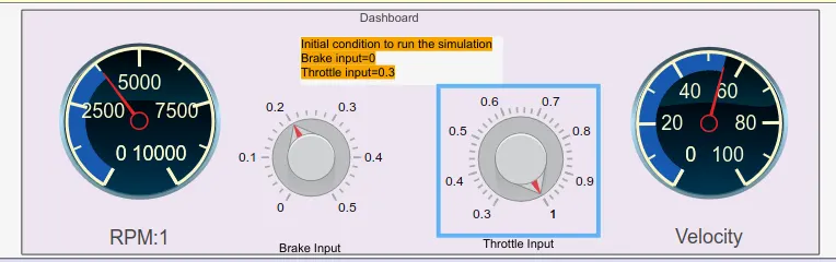
Both the RPM and the velocity value has increased compared to the previous simulation. The engine and torque curve will remain the same we are not changing the CVT ratio here.
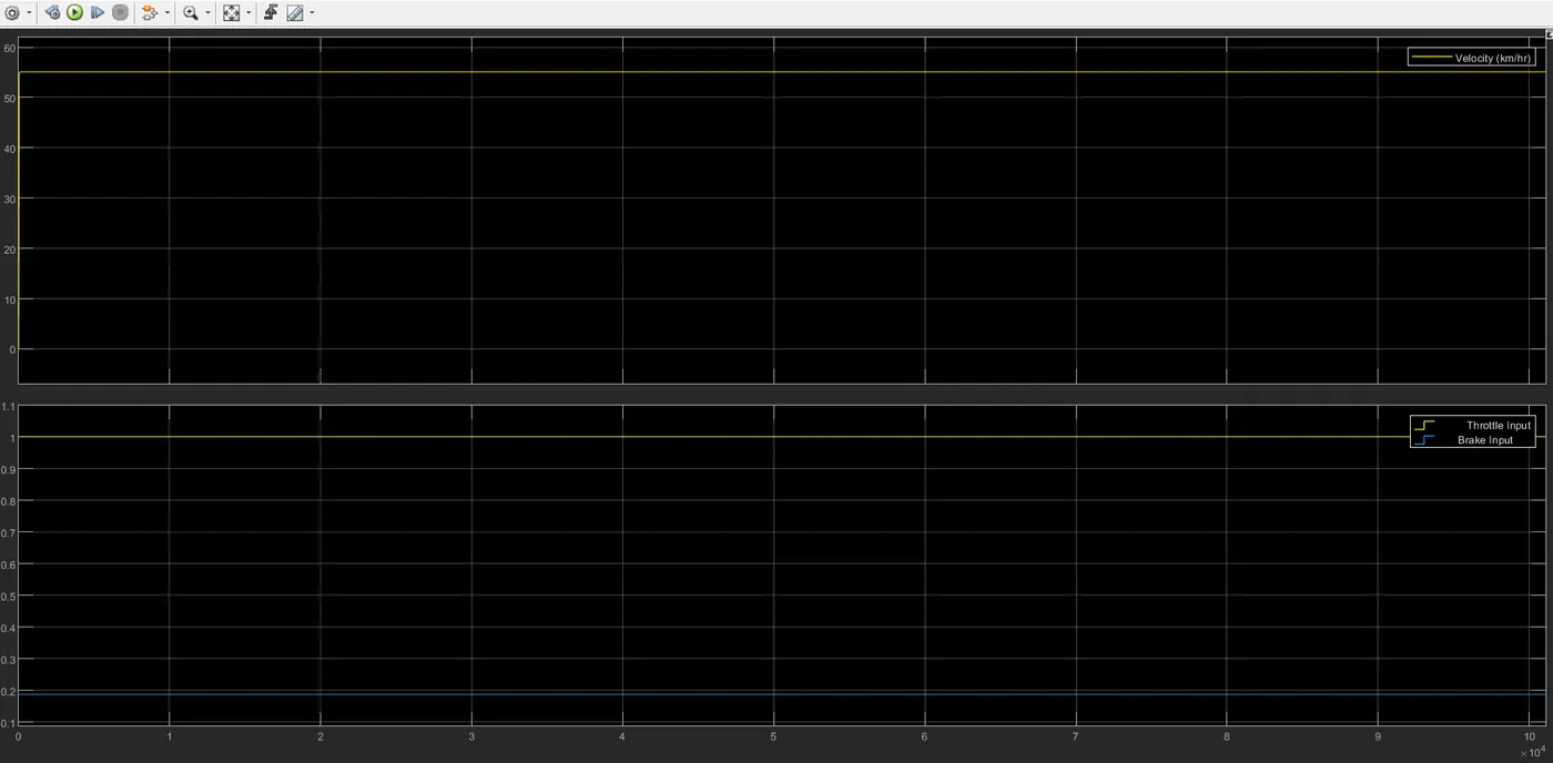
Brake and throttle graph varied according to the input. An increase in the Braking results in a decrease in both the RPM and the Speed.
Case 3: ATV model with the Dashboard & Lookup Table
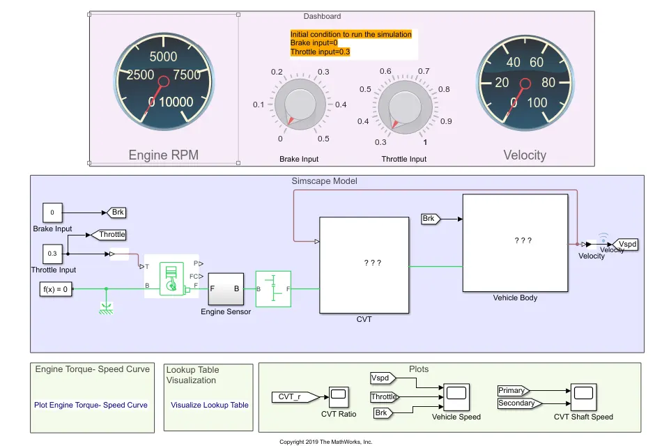
Here along with the previous setup there is an addition of the "Lookup Table"
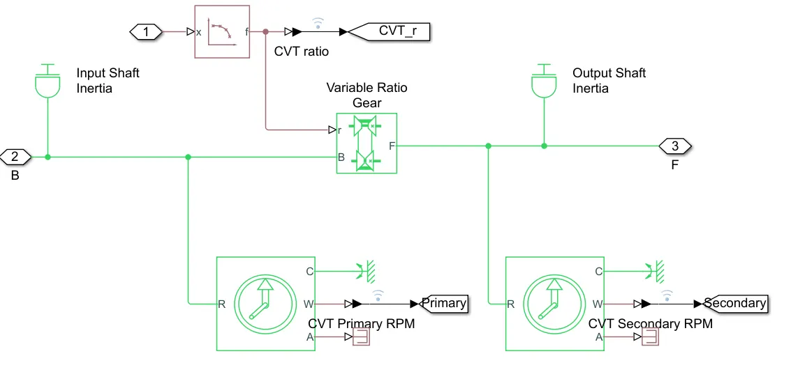
1. To give the values for the "Variable Gear Ratio" block, "PS-look up table" block which represents a physical signal converter whose input-output relationship is specified by a lookup table. The table grid must be in strictly ascending or strictly descending order, but the spacing can be nonuniform. The values generated in the PS-Look up table is connected to the "Goto" block named CVT_r.
2. The CVT ratio arrived using the "PS-look up table" block is shown below, graph obtained through the Signal Builder block has a straight linear decrease in the gear ratio whereas in this there is slight varaiation in the gear ratio as the speed increases.
Output of Case 3:
The output remains the same since there are no chnages in the value. But this time I'm running the simulation with full throttle and brake =0.
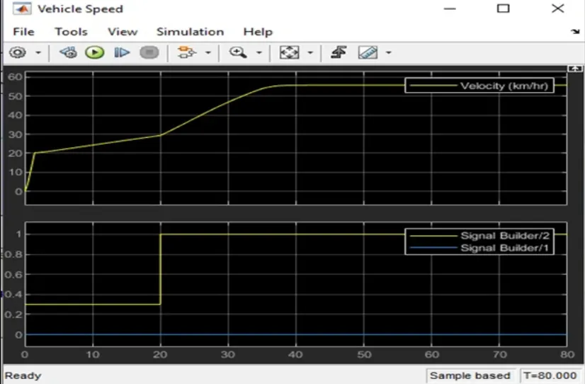
The speed reached around 55kmph 40 seconds ie., exactly 20 seconds after the full throttle is been given. After that it maintains the constant speed.
Case Study 4:
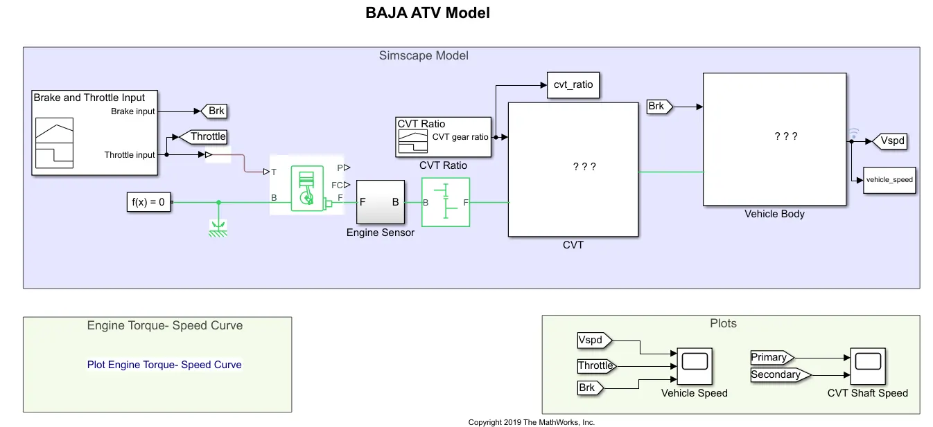
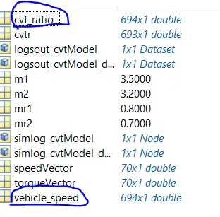
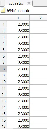
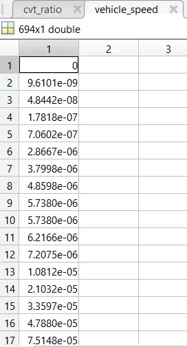
Here the cvt_ratio and vehicle_speed are not published through scope or plotted like the previous models. Instead both these are published in the workspace whose values are shown below.
Case Study 5:
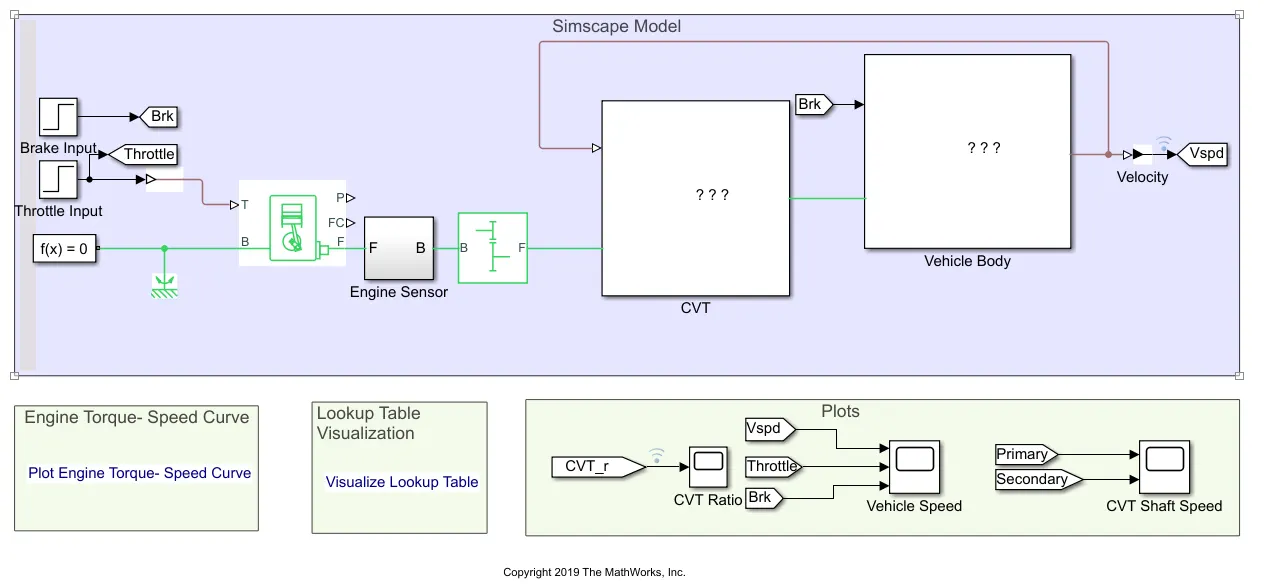
In this case, the inputs for the Brake and Throttle is given through the "Step" block. (earlier it was through signal builder, constant)
Here also the to assign the values Variable Gear Ratio, "PS-look up table" block is used.
Conclusion:
A detailed review and analysis of the All-Terrain Vehicle model were carried out. It helped me to understand how real-time vehicle simulation is carried out.
The simulation end results are same for all the cases. only the way of assigning and depiciting the output has differed from case to case.