Project
AIM:
- Carry out a system-level simulation of an all-terrain vehicle.
- Prepare a technical report explaining the model properties & comments on the results.
All-terrain vehicle
An all-terrain vehicle (ATV), also known as a light utility vehicle (LUV), a quad bike, or simply a quad, as defined by the ANSI; is a vehicle that travels on low-pressure tires, with a seat that is straddled by the operator, along with handlebars for steering control. As the name implies, it is designed to handle a wider variety of terrain than most other vehicles. Although it is a street-legal-vehicle in some countries, it is not street-legal within most states, territories and provinces of Australia, the USA or Canada.
By the current ANSI definition, ATVs are intended for use by a single operator, although some companies have developed ATVs intended for use by the operator and one passenger. These ATVs are referred to as tandem ATVs.
The rider sits on and operates these vehicles like a motorcycle, but the extra wheels give more stability at slower speeds. Although most are equipped with three or four wheels, six-wheel models exists and existed historically for specialized applications. Multiple-user analogues with side-by-side seating are called utility terrain vehicles or side by side vehicles to distinguish the classes of vehicle.

#STUDY 1
- BAJA ATV WITH CVT
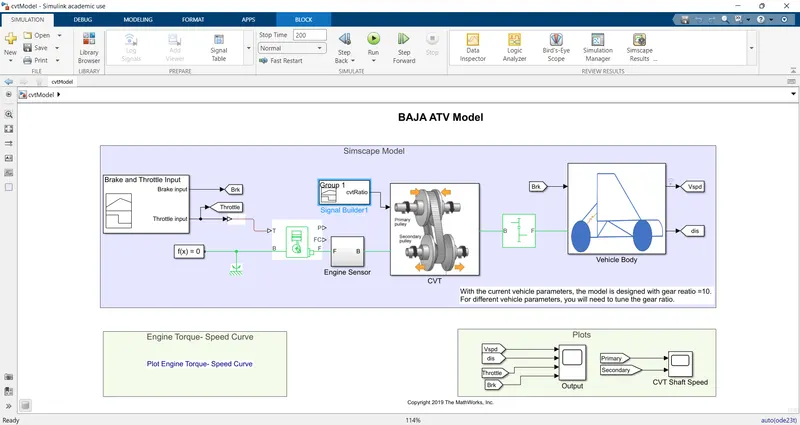
MAIN BLOCKS USED:
- SIGNAL BUILDER:
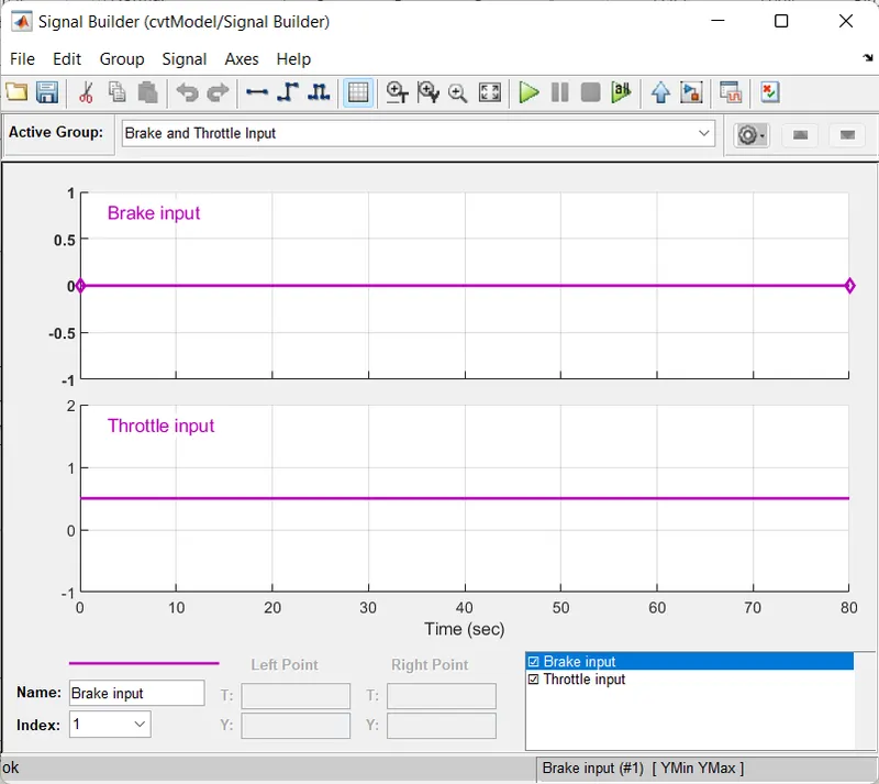
- The SIGNAL BUILDER BLOCK is used as the inputs of break & throttle(accleration) for the BAJA Vehicle during its ride.
- It is connected to the engine via simulink-ps converter as engine is in physical system.
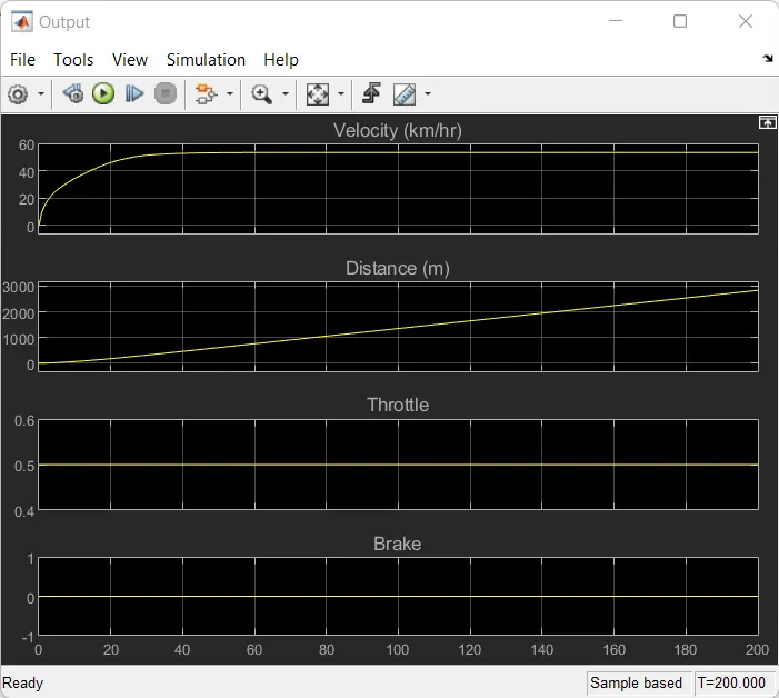
- It has been set and seen from the graph plotted below that the break applied is constant '0' (indicating no break is applied) and Throttle applied is also constant of '0.5'. for a given duration.
2.GENERIC ENGINE:
Description
The Generic Engine block represents a general internal combustion engine. This block is a suitable generic engine for spark-ignition and diesel. Speed-power and speed-torque parameterizations are provided. A throttle physical signal input specifies the normalized engine torque. Optional dynamic parameters include crankshaft inertia and response time lag. A physical signal port outputs the engine fuel consumption rate based on the fuel consumption model that you choose. Optional speed and redline controllers prevent engine stall and enable cruise control.
Engine Speed, Throttle, Power, and Torque
By default, the Generic Engine block uses a programmed relationship between torque and speed that is modulated by the throttle signal.
The block evaluates engine power demand as a function of engine speed, g(Ω). The function provides the maximum power available for a given engine speed, Ω. The block parameters—Maximum power,Speed at maximum power,and Maximum speed— normalize this function to physical maximum torque and speed values.
The normalized throttle input signal T specifies the actual engine power. The power is delivered as a fraction of the maximum power possible in a steady state at a fixed engine speed. It modulates the actual power delivered, P, from the engine: P(Ω,T) = T·g(Ω). The engine torque is τ = P/Ω.
3.ENGINE SENSOR:
- It is built to have a sense of engine's RPM as it runs in the given duration of time.
- The main block used here is RPM Sensor,
- RPM SENSOR:This block measures angular velocity or angle in a mechanical rotational network. The sensor is ideal since it does not account for inertia, friction, delays, energy consumption, and so on.The physical signal ports W and A report the angular velocity and angle, respectively, of port R relative to port C. The measured angular velocity is positive when the angular velocity at port R is greater than the angular velocity at port C.
- The port R is connected to CVT.
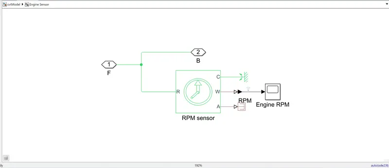
- Further, via ps-simulink converter it is connected to scope which is named as Engine RPM.
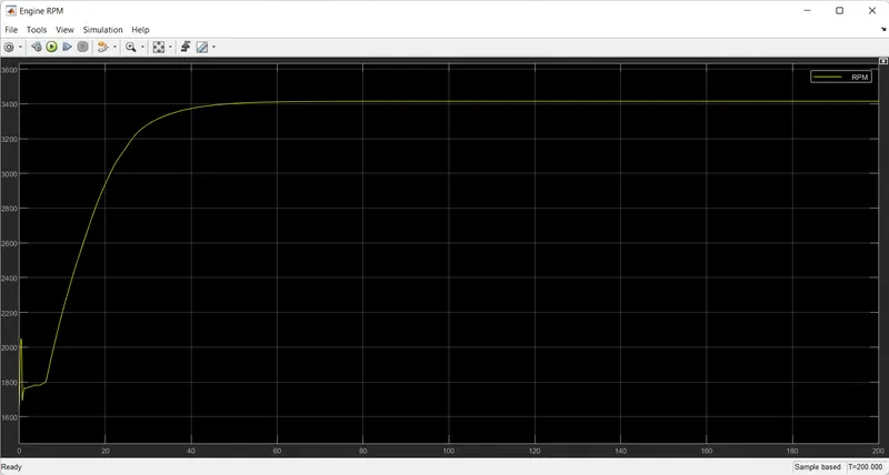
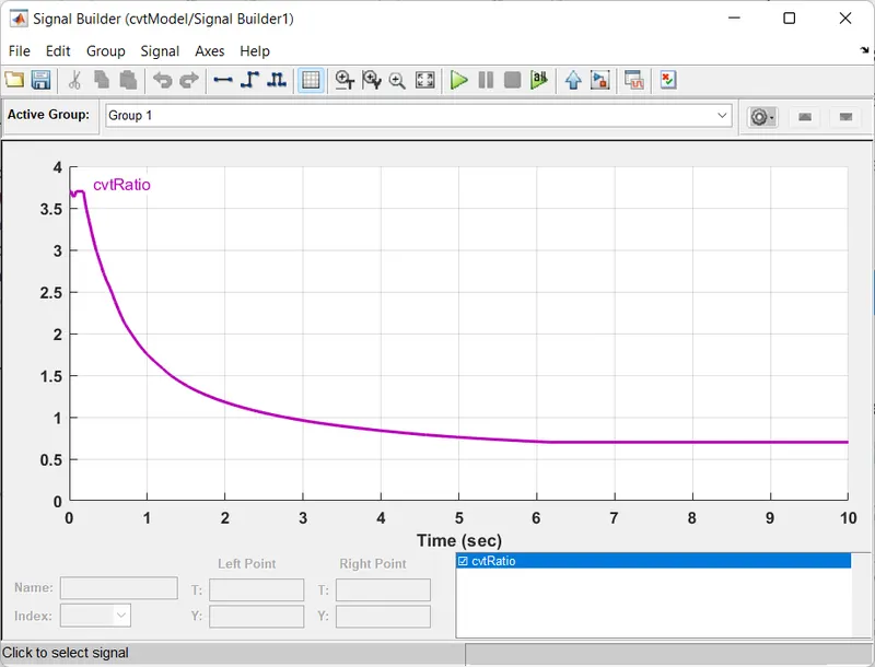
4.CVT RATIO:Ratio range is defined as the numerical ratio of the maximum to the minimum output speeds possible for a given fixed input speed.
Using Signal Builder CVT Model is built as follows:
5.CVT:
- A continuously variable transmission (CVT) is an automatic transmission that can change seamlessly through a continuous range of gear ratios.
- This contrasts with other transmissions that provide a limited number of gear ratios in fixed steps.
- The flexibility of a CVT with suitable control may allow the engine to operate at a constant RPM while the vehicle moves at varying speeds.
- CVTs are used in automabiles,tractors,bicycle and earthmovers.
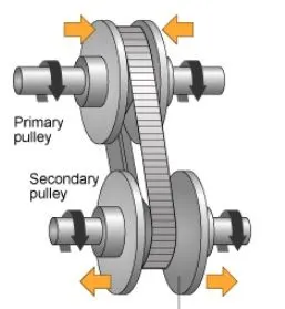
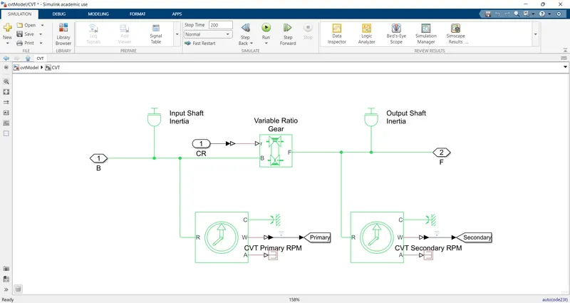
- The main blocks used in CVT are:
- INPUT & OUTPUT SHAFT INERTIA:The simulink block used for both shafts is Inertia Block
-
The Inertia block represents an ideal mechanical translational inertia that is described with the following equation:
T=Jdω/dt
where:
-
T is inertia torque.
-
J is inertia.
-
ω is angular velocity.
-
t is time.
By default, the block has one mechanical translational conserving port. The block positive direction is from its port to the reference point. This means that the inertia torque is positive if inertia is accelerated in the positive direction.
In some applications, it is customary to display inertia in series with other elements in the block diagram layout. To support this use case, the Number of graphical ports parameter lets you display a second port on the opposite side of the block icon. The two-port variant is purely graphical: the two ports have the same angular velocity, so the block functions exactly the same whether it has one or two ports. The block icon changes depending on the value of the Number of graphical ports parameter.
-
- VARIABLE RATIO GEAR:
-
The Variable Ratio Transmission block represents a gearbox that dynamically transfers motion and torque between the two connected driveshaft axes, the base and the follower.
When you choose to have the block ignore the dynamics of transmission compliance, it constrains the driveshafts to corotate with a variable gear ratio that you control. You can choose whether the follower axis rotates in the same or opposite direction as the base axis. If the follower and base axis rotate in the same direction, ωF and ωB have the same sign. If the follower and base axis rotate in opposite directions, ωF and ωB have opposite signs.
Transmission compliance introduces internal time delay between the axis motions. Unlike a gear, a variable ratio transmission does not act as a kinematic constraint. You can also control the torque loss caused by transmission and viscous losses.
- IDEAL ROTATION MOTION SENSOR:The primary & secondary shaft RPM are sensed using this motion sensor.The motion sensor is described as follows:
-
The Ideal Rotational Motion Sensor block represents an ideal mechanical rotational motion sensor, that is, a device that converts an across variable measured between two mechanical rotational nodes into a control signal proportional to angular velocity or angle. You can specify the initial angular position (offset) as a block parameter.
The sensor is ideal since it does not account for inertia, friction, delays, energy consumption, and so on.
Connections R and C are mechanical rotational conserving ports that connect the block to the nodes whose motion is being monitored. Connections W and A are physical signal output ports for velocity and angular displacement, respectively.
6.SIMPLE GEAR:
The Simple Gear block represents a gearbox that constrains the connected driveline axes of the base gear, B, and the follower gear, F, to corotate with a fixed ratio that you specify. You choose whether the follower axis rotates in the same or opposite direction as the base axis. If they rotate in the same direction, the angular velocity of the follower, ωF, and the angular velocity of the base, ωB, have the same sign. If they rotate in opposite directions, ωF and ωB have opposite signs. You can easily add and remove backlash, faults, and thermal effects.
7.VEHICLE BODY: IN THE BAJA ATV MODEL BLOCK WE HAVE A SUB SYSTEM NAMED 'VEHICLE BODY' AND ITS DESCRIPTED AS FOLLOWS:
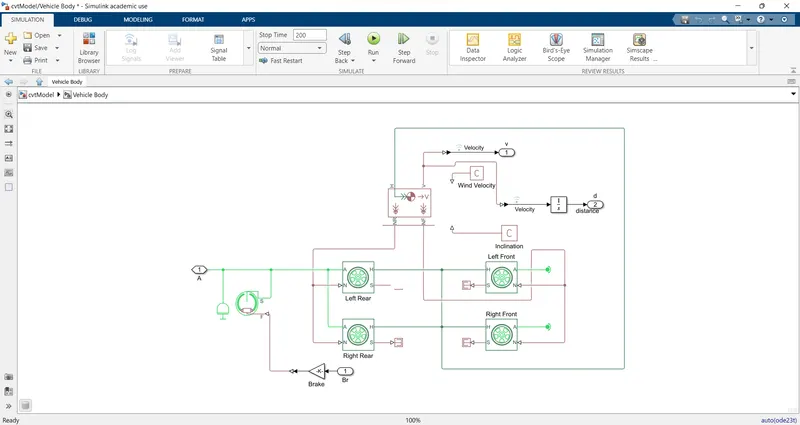
The MAIN blocks used here are:
- Vehicle body:In the below pic the block is indicated by the blue rectangle,and its block parameters are set as per the user.
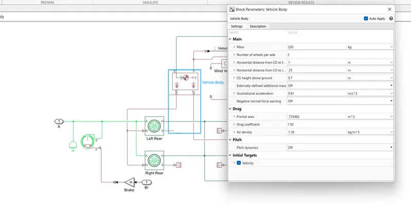
The Vehicle Body block represents a two-axle vehicle body in longitudinal motion. The vehicle can have the same or a different number of wheels on each axle. For example, two wheels on the front axle and one wheel on the rear axle. The vehicle wheels are assumed identical in size. The vehicle can also have a center of gravity (CG) that is at or below the plane of travel.
The block accounts for body mass, aerodynamic drag, road incline, and weight distribution between axles due to acceleration and road profile. Optionally include pitch and suspension dynamics. The vehicle does not move vertically relative to the ground.
The block has an option to include an externally-defined mass and an externally-defined inertia. The mass, inertia, and center of gravity of the vehicle body can vary over the course of simulation in response to system changes.
- TIRE:In the below pic we have shown a block with its parameters set by the user as shown.The same process is followed for rest of the 3 tires as per there requirements.
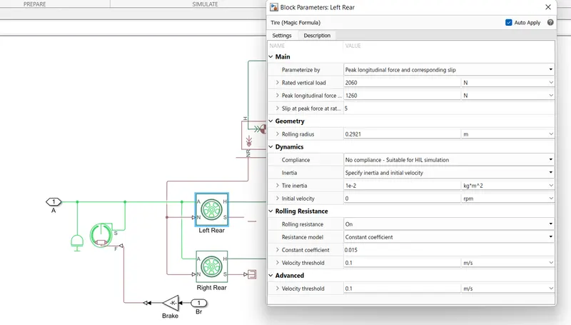
The Tire (Friction Parameterized) block models a tire with friction parameterized in terms of static and kinetic coefficients. The static friction coefficient determines the applied torque at which the tire loses traction and begins to slip. The kinetic friction coefficient determines the amount of torque that the tire transmits to the pavement once it begins to slip. The tire regains traction once its relative velocity over the pavement falls below the traction velocity tolerance specified.
To increase the fidelity of the tire model, the block enables you to specify properties such as tire compliance, inertia, and rolling resistance. However, these properties increase the complexity of the tire model and can slow down simulation. Consider ignoring tire compliance and inertia if simulating the model in real time or if preparing the model for hardware-in-the-loop (HIL) simulation.
- DOUBLE-SHOE BREAK:The below pic shows the Double-shoe break Block with block parameters as set by the user.
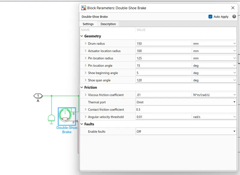
The Double-Shoe Brake block represents a frictional brake with two pivoted rigid shoes that press against a rotating drum to produce a braking action. The rigid shoes sit inside or outside the rotating drum in a diametrically opposed configuration. A positive actuating force causes the rigid shoes to press against the rotating drum. Viscous and contact friction between the drum and the rigid shoe surfaces cause the rotating drum to decelerate.
Double-shoe brakes provide high braking torque with small actuator deflections in applications that include motor vehicles and some heavy machinery. The model employs a simple parameterization with readily accessible brake geometry and friction parameters.
You can also enable faulting. When faulting occurs, the belt will exert a user-specified force. Faults can occur at a specified time or due to an external trigger at port T.
- PS-CONSTANT:Here,it is used for both inclination & wind velocity by setting the parameters.
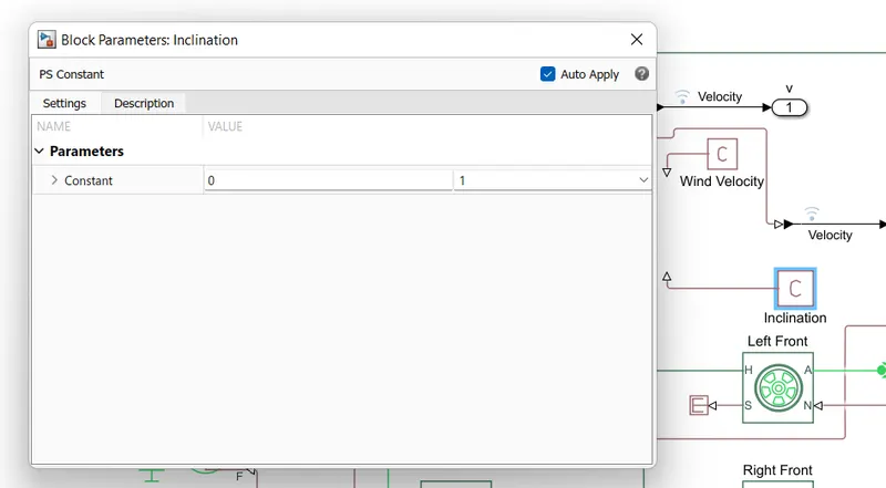
The PS Constant block generates a physical signal of a constant value. You specify the value and unit of the signal as the Constant parameter.
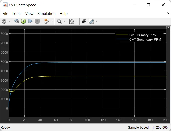
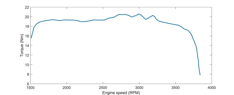
THUS AFTER EXECUTION OF THE SIMULINK MODEL WE GOT THE OUTPUT RESULTS AS FOLLOWS:
1.OUTPUT PLOT:
2.CVT SHAFT SPEED PLOT:
3.SPEED v/s TORQUE
#STUDY 2
- BAJA ATV WITH CVT & DASH BOARD.
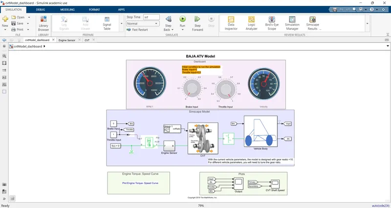
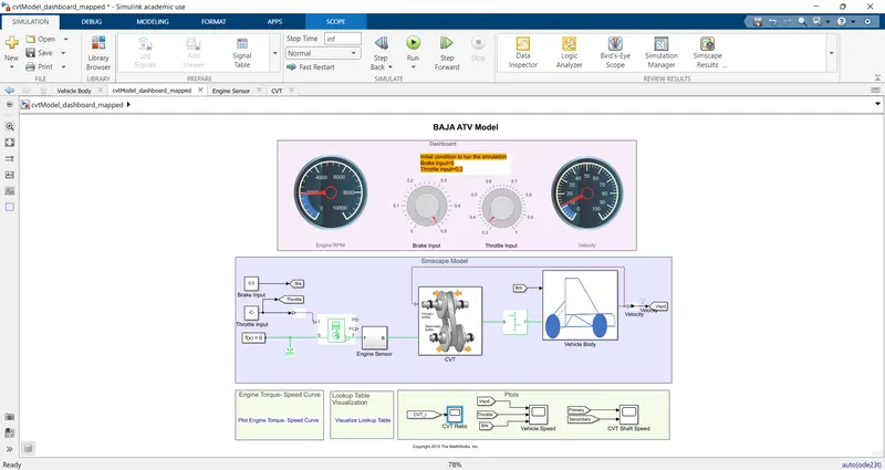
"HERE, THE PROCESS AND FUNCTIONS ARE SAME AS MENTIONED IN THE #STUDY 1,BUT IN THIS WE HAVE REMOVED THE SIGNAL BUILDER FOR ENGINE INPUT AND ADDED THE CONSTANTS FOR THROTTLE AND BREAK INPUTS AND ASSIGNED THE KNOBS TO CONTROL WHICH CAN BE SEEN THROUGH CUSTOM GAUGES IN THE DASHBOARD".
THE STOP TIME IS SET TO 'INF' AS THE INPUTS ARE CONTROLLED BY THE USER WITH KNOBS
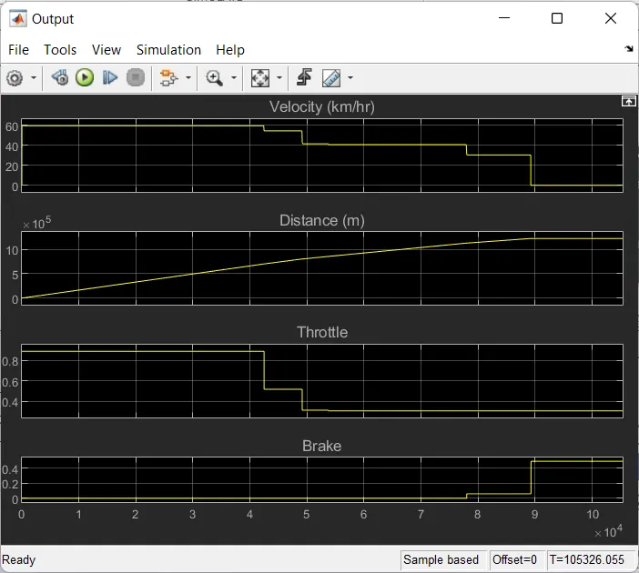
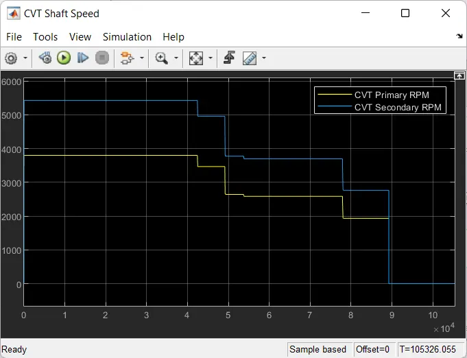
TO DEMONSTRATE THE OUTPUTS, WE HAVE ADJUSTED THE KNOBS AS PER OUR WISH AFTER RUNNING WE GOT THE RESULTS AS FOLLOWS:
1.OUTPUT:
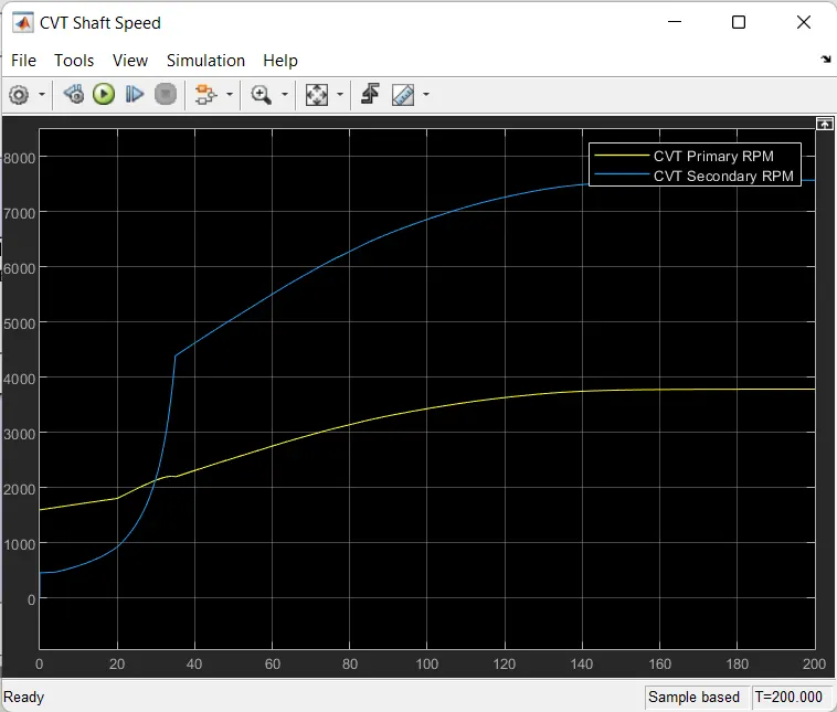
2.CVT SHAFT SPEED :
#STUDY 3
- BAJA ATV WITH CVT & LOOKUP TABLE.
-
What is a lookup table
A lookup table is an array of data that maps input values to output values, thereby resembling a mathematical function. If there are a given a set of input values, a lookup operation retrieves the corresponding output values from the table. In other words, a lookup table computes an approximation to some mathematical function y=f(x), given data vectors x and y. We can define the lookup table by specifying a vector of output values parameter as a l-by-n vector. The lookup table block in Simulink generates an output based on the input values using one of the methods selected from the Look-up method parameter list. If the lookup table does not define the input values, the block estimates the output values based on a nearby table
- HERE,WE HAVE REPLACED THE SIGNAL BUILDER BY A n-D LOOKUP TABLE.
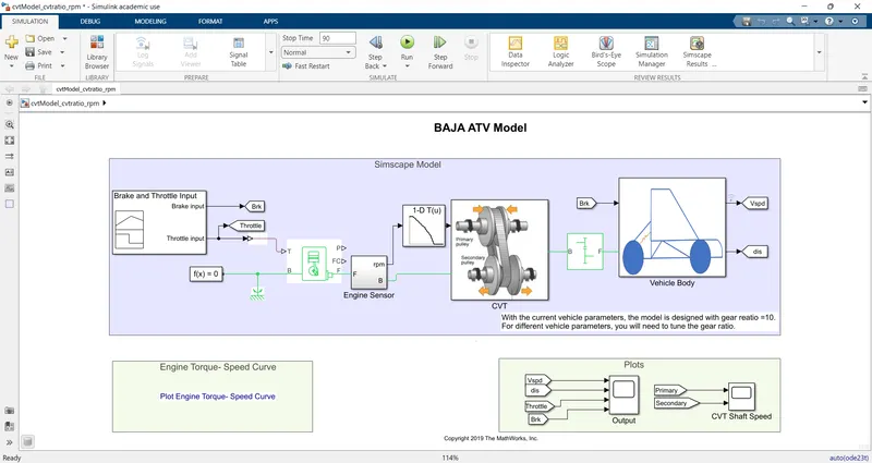
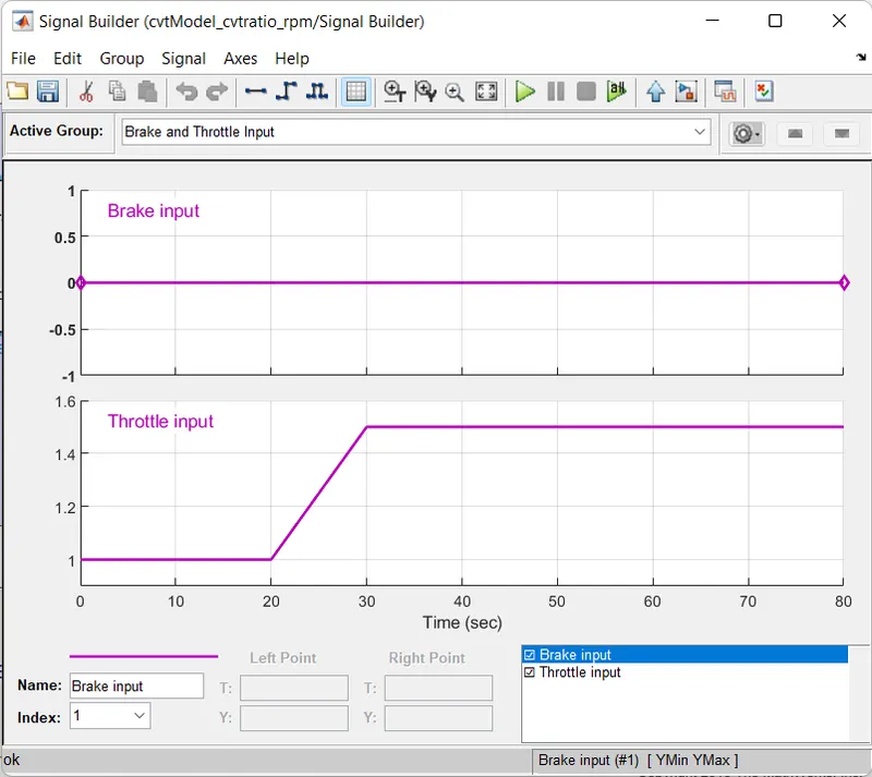
SIGNAL BUILDER:WE HAVE CHANGED THE INPUTS AS FOLLOWED:
RESULTS AFTER RUN:
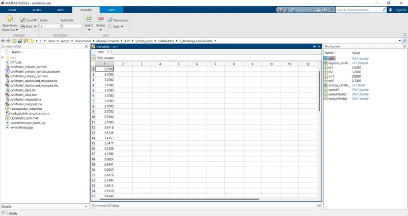
WORKSPACE:
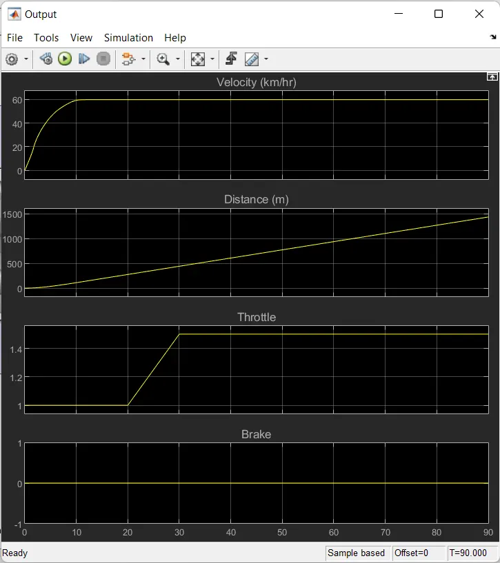
1.OUTPUT:
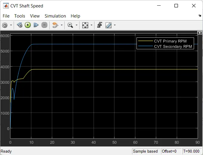
2.SHAFT SPEED CVT:
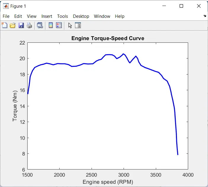
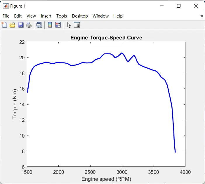
3.ENGINE TORQUE-SPEED CURVE:
#STUDY 4
- BAJA ATV WITH CVT & MAPPED WITH DASHBOARD.
SUB-SYSTEM CVT:
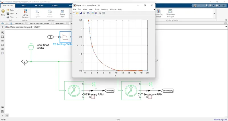
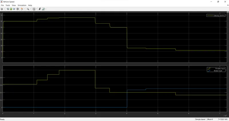
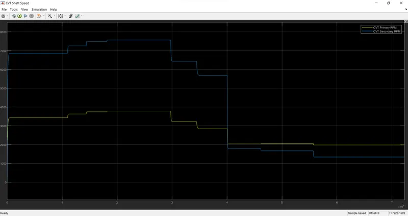
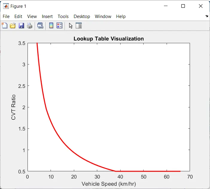
Using PS lookup table we have set the methamatical function parameters as 1D(linear) which provide the output based on the inputs assigned .The inputs assigned are a set of data which are velocities of the vehicle.Thus, the graph is plotted as shown above.
For demonstration we have runned the model as per our input
AFTER RUNNING THE MODEL we got the RESULTS as follows:
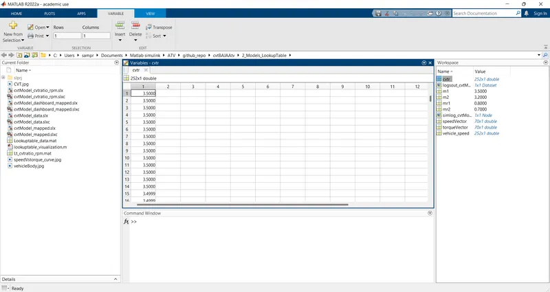
1.Workspace
2.Vehicle speed:
3.CVT shaft speed:
4.cvt ratio v/s vehicle speed:
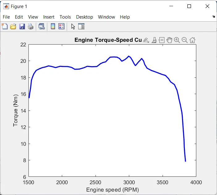
5.Engine torque v/s speed:
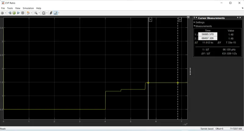
6.CVT Ratio:
#STUDY 5
- BAJA ATV WITH CVT & MAPPED
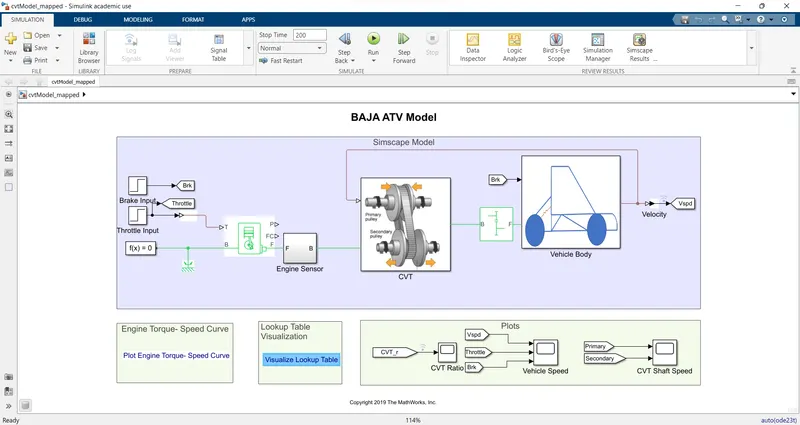
IT IS A SAME MODEL AS MENTIONED IN #STUDY 4 & THE RESULTS ARE ALSO THE SAME,THE ONLY CHANGE IS WE HAVE REMOVED THE DASHBOARD.WHICH DOES NOT ALLOWS US TO CONTROL THE INPUTS OF BREAK & THROTTLE.
#STUDY 6
- BAJA ATV WITH CVT & To Workspace.
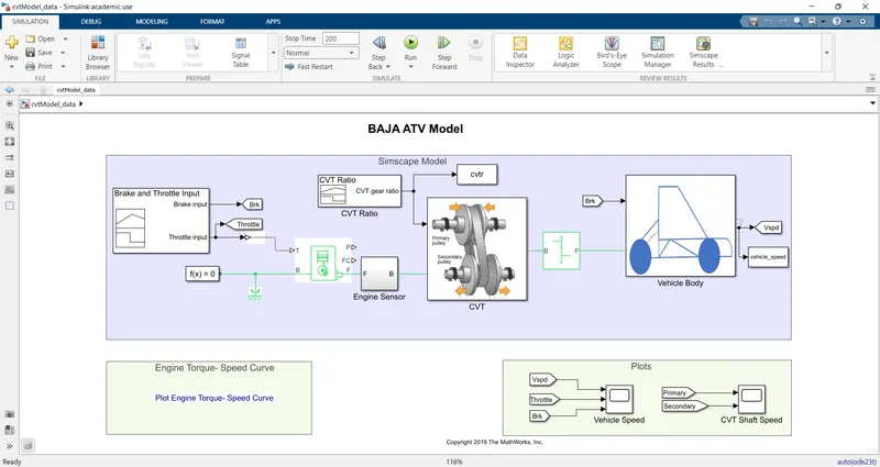
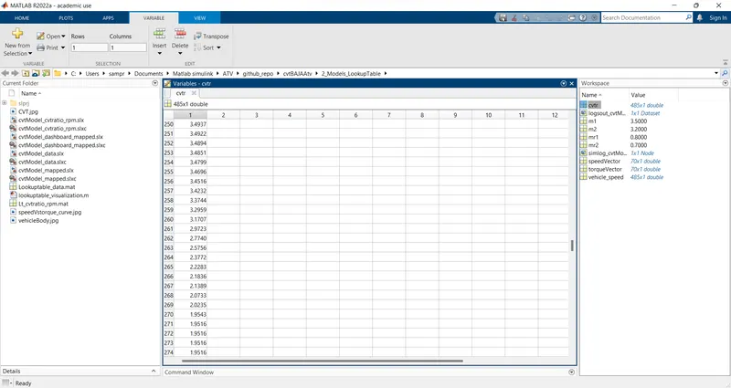
Here we have connected the 'To Workspace' Block with CVT ratio signal builder.
Description of 'To Workspace':
The To Workspace block logs the data connected to its input port to a workspace from a Simulink® model. Typically, logged data is returned in the base workspace. When you simulate a model programmatically inside a function, logged data is returned in the workspace for the function. During simulation, logged data streams to the Simulation Data Inspector. Logged data is written to the workspace when the simulation pauses or stops.
You can use the To Workspace block to log data for a signal, a bus, or an array of buses. The To Workspace block supports logging scalar and multidimensional data, including data for variable-size signals.
You can configure the name of the variable that stores the data the To Workspace block logs, and you can specify the format for the logged data. You can also control which values the To Workspace block logs by specifying block or model parameters.
THE BELOW IMAGE IS A WORKSPACE AVAILABLE USING 'TO WORKSPACE' BLOCK:
RESULTS AFTER RUNNING THE MODEL:
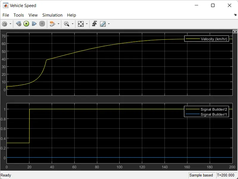
1.VEHICLE SPEED:
2.CVT SHAFT SPEED:
3.ENGINE TORQUE-SPEED CURVE: