Project
To carry out a system-level simulation of an all-terrain vehicle.
we are to write the properties and the functions of an all terrain vehicle model
Baja competition:
the model is made to interpret the actions of a continuous variable transmission and all the necessary components to make an all terrain vehicle system.
the model of the baja vehicle is taken into consideration as we are to calculate the input and outputs of the important components of the vehicle.
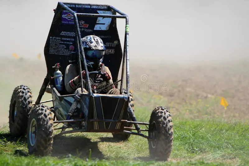
the baja competition run by the society of automotive engineers international(SAE International). Teams of students from universities all over the world design and build small off road cars. The cars all have engine of the same specifications. As of 2018 the engine has been an unmodified briiggs and straton Model 19 Vanguard engine single cylinder with a displacement of 305cc and power output of approximately 10 bhp (7.5 kW).
ALL TERRAIN VEHICLE(ATV):
An all-terrain vehicle (ATV) is defined as a motorized off-highway vehicle designed to travel on four low-pressure or non-pneumatic tires, having a seat designed to be straddled by the operator and handlebars for steering control. ATVs are subdivided into two types as designated by the manufacturer. Type I ATVs are intended by the manufacturer for use by a single operator and no passenger. Type II ATVs are intended by the manufacturer for use by an operator and a passenger, and are equipped with a designated seating position behind the operator. Similarly, riders must also consider the various ATV sizes. the atvs we use in the baja competition is similar to it but with few restrictions in the engine power and the basic shape.
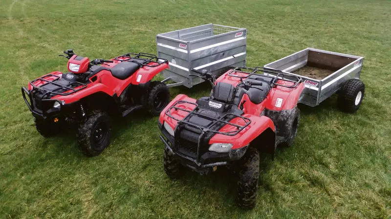
baja atv model:
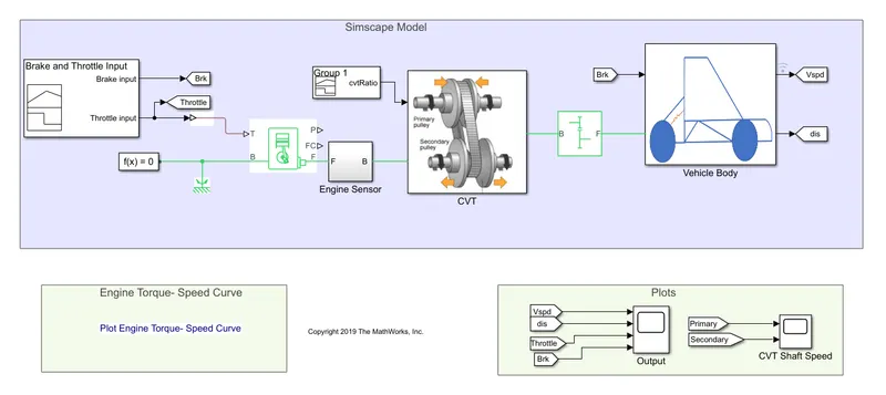
the components of the above system contains many essential components that makes up the vehicle. few of the above important parts are engine, continuous varying transmission(cvt) and vehicle body.
GENERIC ENGINE:
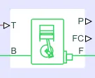
it acts as the source of power to the entire model process. it gives out the speed and torque value of the system for the brake and throttle response we provide to it as input
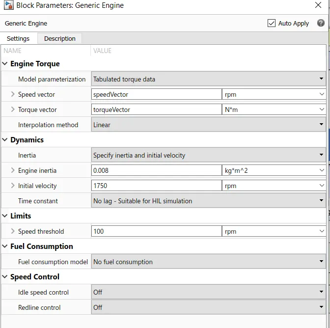
IT HELPS IN TAKING IN THE VALUES OF THE TORQUE, DYNAMICS AND ALL THE OTHER ESSENTIAL ENGINE WORKINGS.
the input to the engine is provided with the help of signal builder block.
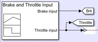
it takes in the values of the brake input and the throttle response and provides them onto the engine for the engine output.
the signal builder block help in achieving the change in the throttle and brake values with respect to time.
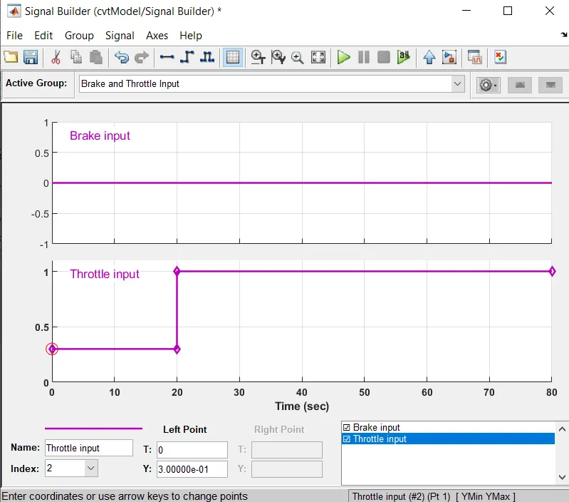
the throttle input is made to be at 0 for a span of first twenty seconds and then made to change from 0 to 1. the brake value id kept constant at 0.
these values are fed into the engine and the engine produces the speed and torque for the vehicle.
the values from the engine is then fed to a gear ratio block where few corrections are made to the gear input for the continuously variable transmission(CVT)
the gear ratio is checked for different values as we are assuming the model for our atv. the ratios are tried for three different values
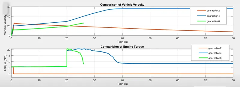
the value of the above plot shows the change in velocity and torque for different values of the gear ratio.
when the gear ratio is set to 2, the engine seems to produce very less torque and the torque is not very much helpful iin inceasing the velocity of the vehicle.
when the gear ratio is set to 8, the engine seems to produce very high output that the torque produced is sudden and reaches the maximum vehicle speed but the vehicle couldn't tackle it and produce better performance
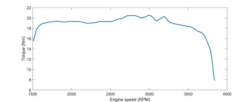
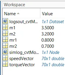
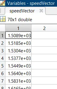
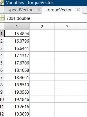
when the ratio is at 8, we can see it attains a torque around twenty six and not higher because the rpm of the vehicle is maxed out and it cannot produce much more than it value. the baja vehicles are made to produce a max rmp of 3840, which is produced quicked and failed to produce enough torque to pull the vehicle and so the velocity is low
when we set the ratio to 4 the vehicle seems to act the way we want by gradually producing the torque we need and the velocity of the vehicle seems to act right. the vehicle seems to move the way it needs to.
then this gear ratio is fed into the cvt for the correct operation of the vehicle.
continuously variable transmission(CVT):
it helps in achieving smooth gear shifts in a vehicle and in achieving fuel economy.
the cvt system is provided next to the engine, where it takes in the engine output and converts the power according to the output required
the cvt system doen not require any gear shifter in the vehicle it changes the speed of the engine output accordingly to the speed we require.
the system is smooth and reduces the fuel consumption of the vehicle as it seems to run in an effective automated way.
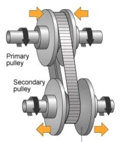
the working of the system is very effective, it contains two pulleys the primary and the secondary.
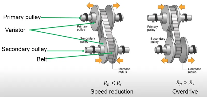
the two pulleys are connected to the engine output and other to the vehicle output.
the primary pully is connected to the engine shaft which takes in the engine power output and provides it to the vehicle according to the power required by the vehicle.
the power transmission is made possible with the help of a chai or a rubber belt in between the pulleys. it is of two types a rubber belt or a metal belt
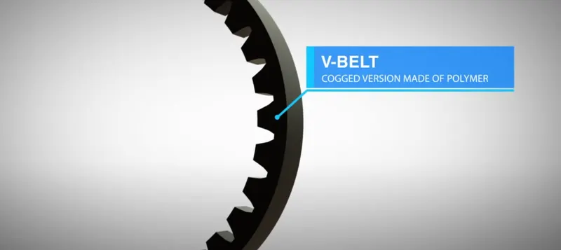
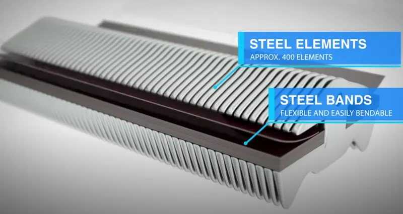
these belts move with in the pulleys and provide power transmission. the pulleys are made of movable plates called sheaves.
they help in achieving the varying speed output.
the rubber belt or the metal belt rests in the sheaves of the primary and the secondary pulleys. there are two sheaves in each pulley. if the sheaves are made to move in direction opposite to each other then the belt lower down and rests on the shaft which makes the radius of rotation smaller, if the sheaves in the other pulley are made closer then the radius of rotation for the belt becomes big in that pulley. with the help of change in radius of rotation of both pulleys we can achieve varying speed output.
two wheelers use sheaves with centrifugal weights inside their sheaves to achieve change in sheave direction and car and big vehicles use hydraulic to achieve sheave motion. the change in sheaves are made possible with the help of pedal shifters in many cvt transmission cars.
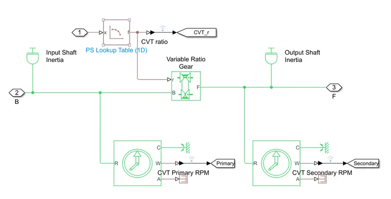
when we get into the cvt block we can see
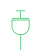
these are the primary and secondary pulleys representation
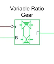
this acts as the cvt action block. tha is it specifies the gear ratio.
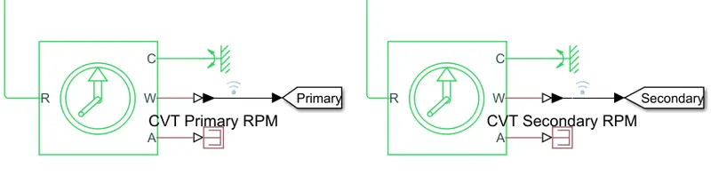
they act as sensors in understanding the changes in primary and secondary pulley.
the whole cvt model:
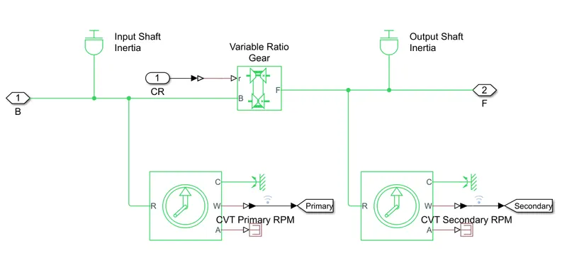
the output from the cvt is then sent into the vehicle body for the proper running of the vehicle.
the vehicle body model:
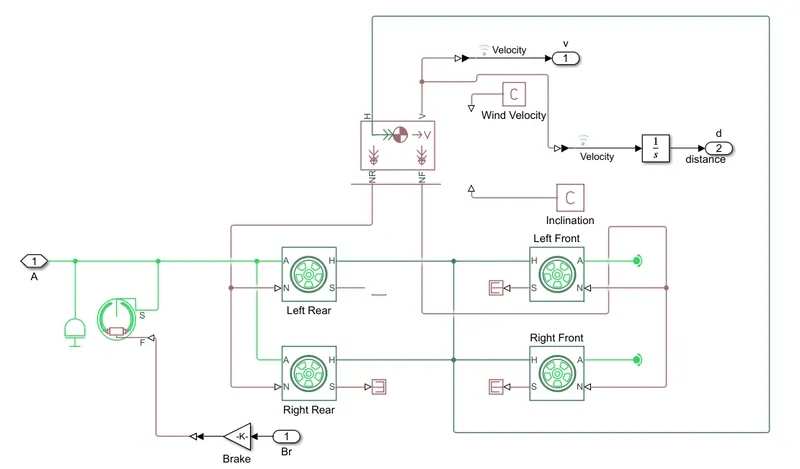
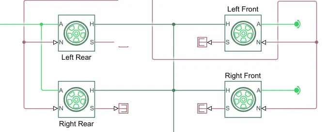
the above model contain vehicle bode block, wheel model block.
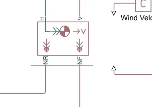
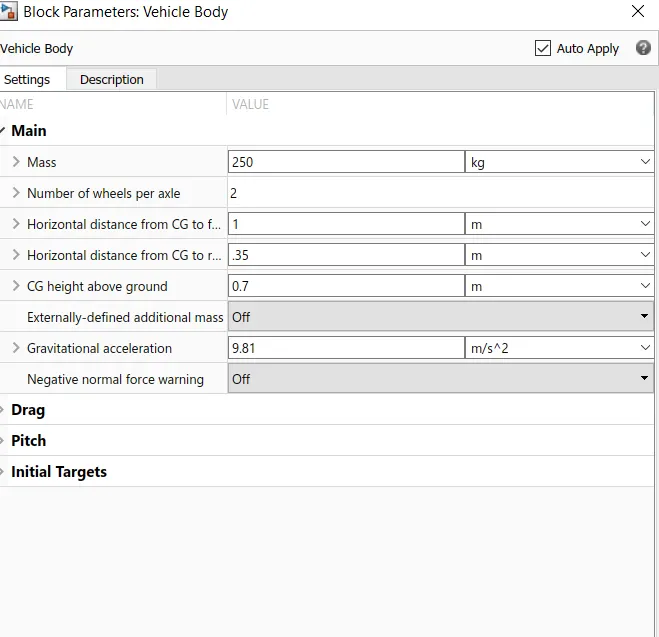
the vehicle body block takes in the mass value of the car, no of wheels in the each axle etc..
the wheels provided are basic types in the above model and can be changed according to our needs
this is the complete representation of the model of atv
the change in mass of the vehicle will provide values of such
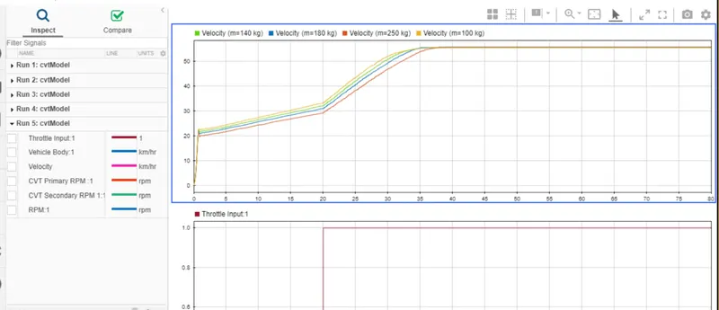
the plot shows different mass given to vehicle and the time taken for it to reach its maximum velocity.
they all reach the same velocity but in different time. the time taken by a vehicle of mass less is shown to reach the required velocity faster than mass greater than that
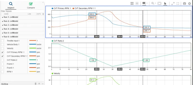
the primary and secondary rpm changes with respect to the input cvt ratio.
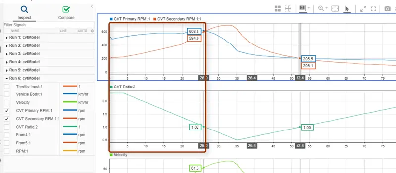
we can see that the ratio when greater than one, the primary rpm is greater than the secondary rpm. this will make the vehicle move slow even if the engine speed is higher.
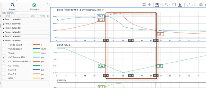
when the ratio is less than 1, the secondary rpm seems to going higher than the primary rpm this will make the vehicle wheels overdrive. and when ratio changes again to grater than 1 then backs again with lower speed than engine.
WHEN GIVING IN THE CVT DATA RATIO AND CHECKING FOR PERFORMANCE OF VEHICLE:
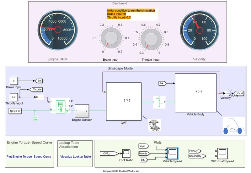
the model is similar to the above block, but we have attached few components like visual display block to engine rpm and velocity and varying input switch for brake and throttle. these are taken as a subsystem called dashboard.
the change that happend here is that the cvt ratio in the previous model is taken out and the cvt ratio is provided from the lookup table that is feeded into the cvt block.
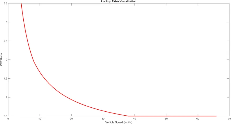
the script written for logging the cvt ratio to the cvt block is
%% Load and simulate the model
cvtModel_data
sim('cvtModel_data')

%% Visualize the lookup table
plot(vehicle_speed,cvtr,'r','LineWidth',2)
xlabel ('Vehicle Speed (km/hr)')
ylabel ('CVT Ratio')
title ('Lookup Table Visualization')
this is made as a script input with the help of matlab.
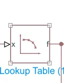
this diagram represents the lookup table and the connection to the cvt block is done as below
the lookup table feed is given in as below
by adding the throttle and brake varying input we can find the actual working process of the vehicle with respect to throttle, speed of vehicle and the power of braking.
for example:
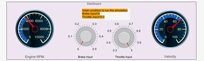
when we give in the throttle response as 1 and the brake 0 we can see that the velocity increases with respect to the throttle and the time.
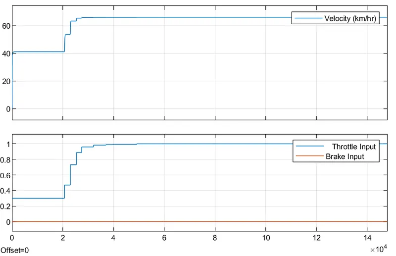
the response is given in the above plot.
likewise when we add break to the input we can see what is happening below
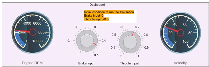
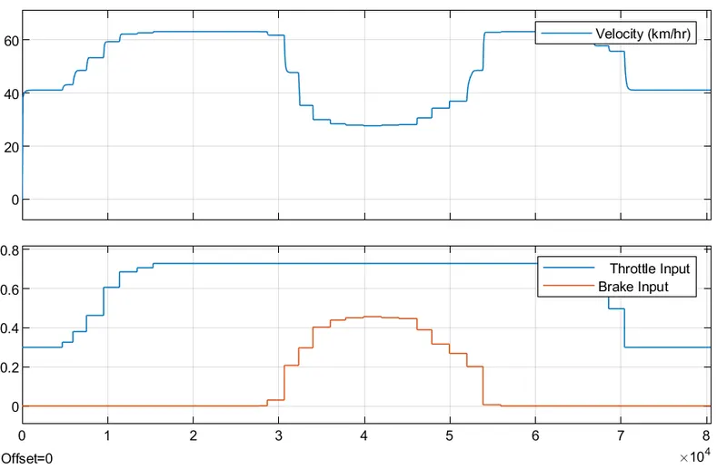
we can see that the velocity curves similar to the throttle response and when the braking is active the velocity decreases.
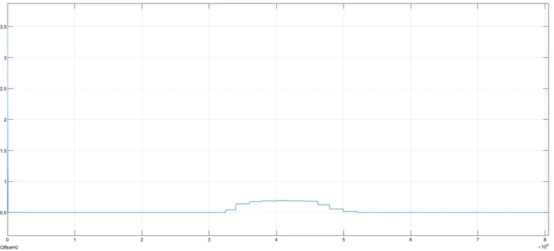
and the cvt ratio is as follows
ERRORS:
There were few errors when the models lagged loading the image for the blocks, which are then corrected using the image block.
CONCLUSION:
system level simulation of an all terrain vehicle is carried out and the model properties of the simulink blocks are explained with their technical properties.
the knowledge about the model is acquired from the matlab official website.