Project
Aim: To detaile case study of contineuos transmistion vechicle using BAJA ATV vechicle and present our observation on it.
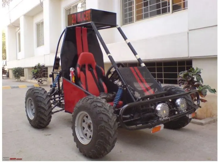
Information: All terain vechicle: all tersin vechicle (atv( also callde as rherrre ,four wheeler off road by American National standard institut is vechile travelled on low pressurre tires with seat straddeled by operator.BAJA ATV : its an ebvent for undergraduated studet (engineering) its task given to student to crat e desig ,fbrication, validate the design for single seater foure wheeler off road vechicle .
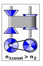
(cvt) contineous variable transmision is an automatic transmision that can change seamlessly to continous range of gaear ratios .this contrast with other transmisoin which provide limited no. of gear ratios in fixed step and its flexibikty is allow to engine operate at constant RPM and variable speed. CV are used in automobile,tractors ,scooters ,earthmooving equipment , mostly use two pully connected by a belt or chain .
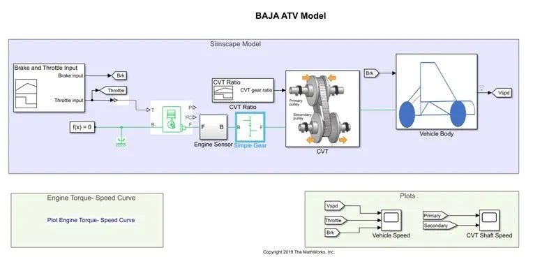
Block used:
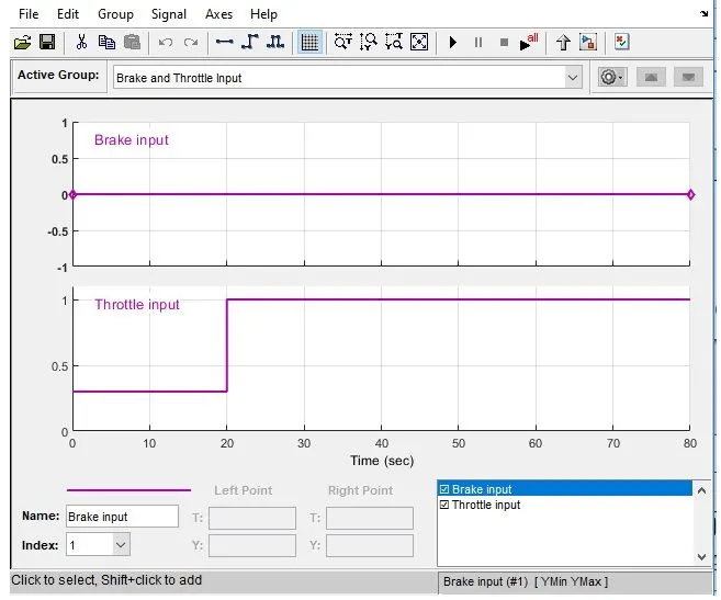
Signal builder: its used to giving input value of brake input and throttle input and it coonnected with generic engine block.
brake input =0 and throttle input =0.3 for first 20 sec after 20 sec throttle input will be 1.
Generic Engine: it repesent system level model of spark and diesel engine suitaible at initial stage of modelling when only the basic parametre are available ,optional ideal speed and real line controller are included.
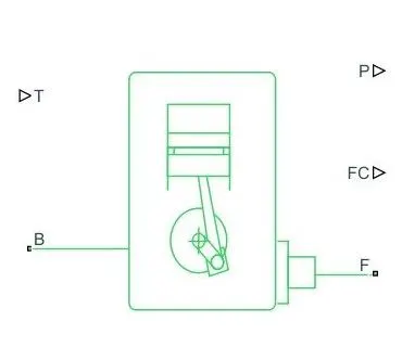
connectin F and B are mechanical rotational conserving ports associated wuith the engine crankshaft and engine block respectively connection P and FC arephysical signal oout put ports through which engine power and feul consumption rate are reported.
Torque vector and speed vector value are alraedy assigned in the matlab data in arrey set .
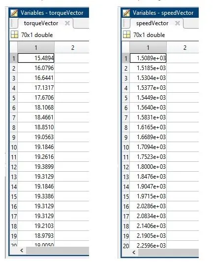
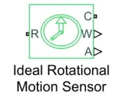
Engine Sensor: its coneected with generic engine. it contin ideal mechanical rptational sensor that convert an across variable measured between two mechanical rotaional nodes into control signal proportional to angular velocity or angle. conection R and C are mechanical rotaional conservig ports and connection W, A are physical signal output ports for velocity and angular dispalcement respectively.
Simple Gear: engine is connecting to cvt with simple gear ratio for speed reduction.
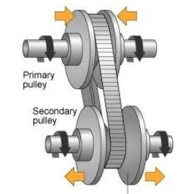
Main component : primary pulley,secondary pully,variator,belt.
case 1: if priamary pully go outward and secondray pully goes inward it will lead to reduction of speed and vise versa.
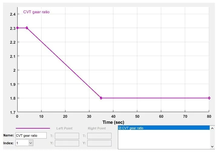
CVT Ratio(signal builder):its connected with cvt by giving random ratio values to get the value velocity for those random CVT ratio.
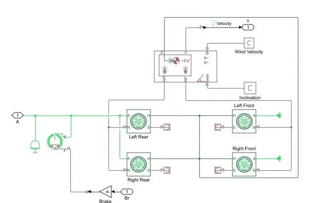
Vehicle body:
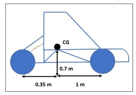
it contain two front wheel and two rear wheel which is connected with inertia output shaft and double shoe brake
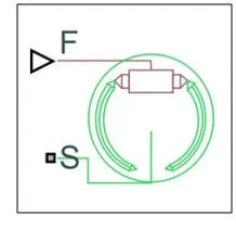
Double shoe brake:it reoresent frictionsl brake with two pivoted rigid shoes that press against rotating drum to produce braking action.port S is for rotsationl conserving port associated with rotsting drum shaft and F is for physical signal input
Other Block:
Simulink to ps convrtor : to convert the simullink signal to simscape enviornment
Solver XConfiguration:to specify the solver parametr before starting the simulation
Mechanivcal Reference:to make sure all component are clamped to ground
PS to Simulink Convetrtor:to convert simscape signal to simulink enviornment
Scope: to view the graph for brtter understanding
Display:to view calculayed engime power.
Inertias:to represent the solid inertia.
Rotational motion sensor:to sens the rotational motion from the engine and give output.
Variable gear ratio:To vary the speed according to gear ratio.
RS terminator: terminator for unconnected physical signal out[ut.
PS constamnt: generate constant physical signal.
Tire: for transportaion of vechicle.
Rotational free end:for mechanicl component
Vechicle body:to represent BAJA ATV model
coustom measure gauge: to measure brake and throtlle input.
Knob: to increse and decrese and vice versa of throttle and brake input
Lok up table:to insert the cvt values from workspace.
step:to increse and decrese an input value for defind time intrval.
Case study:1. BAJA ATV with CVT.
Result:engine torque vs speed torque.
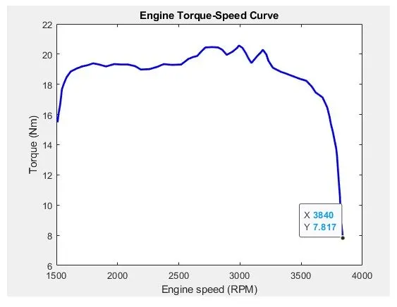
in the above plot maximum velocity reaches at 3840 rpm,vechicle speed depend on CVT ratio
Vehicle Speed plot:
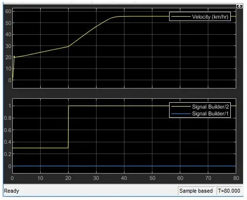
in above plot Brake inout is 0 and throttl input us 0.3 for 20v sec. velocity will reach at 20 and b y increasing the throttle input value to 1, then velocity value is increse and it reaches the maximum velocity.
CVT shaft speed plot:
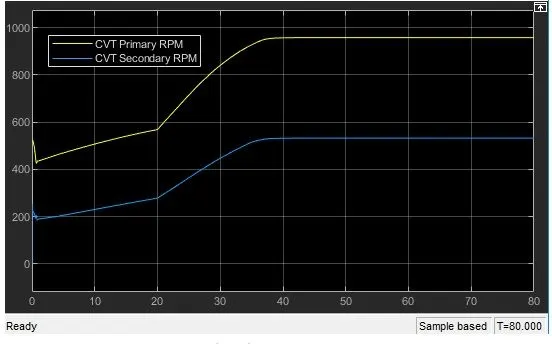
in this primary pully go inward and secondary pully go outward it will lead to over drive,primaary pully radius increase and secondary pulley radious decreses, so speed of primary pulley is greater than secondary pully.
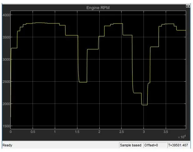
Engine speed:
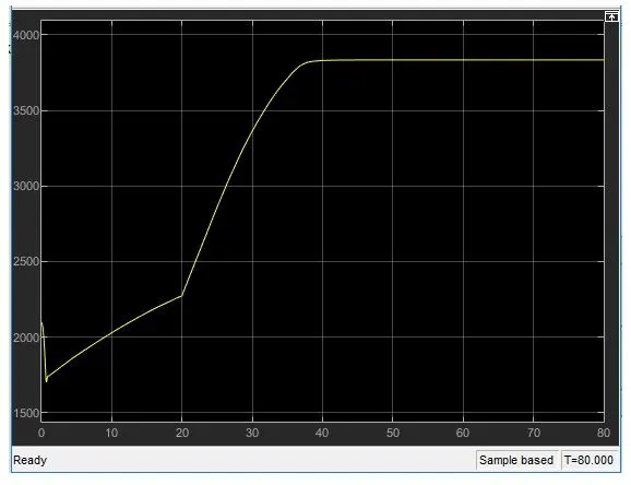
here brake input is 0 and throttle input is 0.3 for 20 sec. engine speed will decraes at beggining because of incresing gear ratio whichnis increase torque ,and by increasing the throttle input value to 1, then engine speed value is increse and it reaches at maximum speed.
Case 2:
ATV with CVT using dashboard:
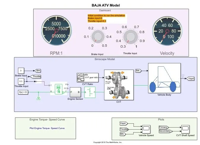
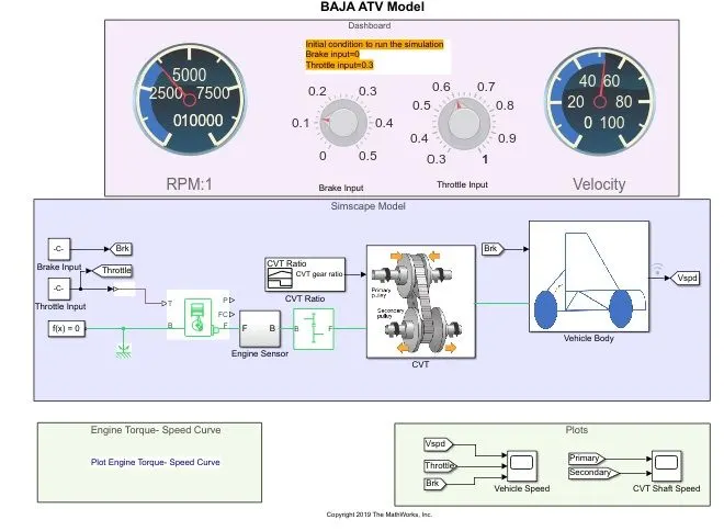
in above simulink model PRPM gauge ,Brake input gauge ,throttle input gauge and velocity gauge is connected in dash board brake input is 0 , throttle input is 0.3 for initial condition to run the simulstion ,Dashboard is cionnected with BAJA All terain vechicle using CVT in simulink model with the help of dash board ,Variation of speed and velocity will display in the RPM :1 gauge and velocity gauge ,while runnig the simulatuion , RPM refers the speed of primary and secondary pully and velocity gauge refres the speed of the vechicle.
Result:in initial condition RPM1:gauge shows 0 rpm and velocity gauge shows 0 km/hr, giving time values as 'inf' and run the simulation ,while runnign the simulation throttlr input value and brake input value can change in respectively gauge in dash-board and analyse the variation of rpm and speed
Vechicle speed plot:
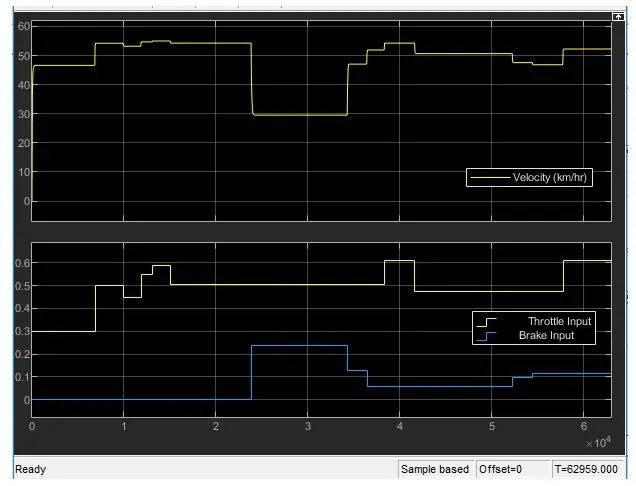
by observing that when increse the value of throttle input increse the velocity and by increasing the brake value decresing the velocity.
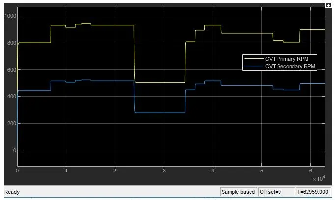
CVT shaft speed plot: from plot ,incresing throttle input value ,increse the rpm of primary and secondary pully and it will decrese when decrse the rpm of both pully.
Engine speed: engine speed increse when incrse the throttle speed and decrese when increse the brake input value.
Study 2
case 1:ATV with CVT using look up table:
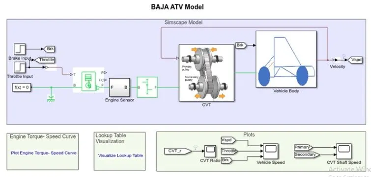
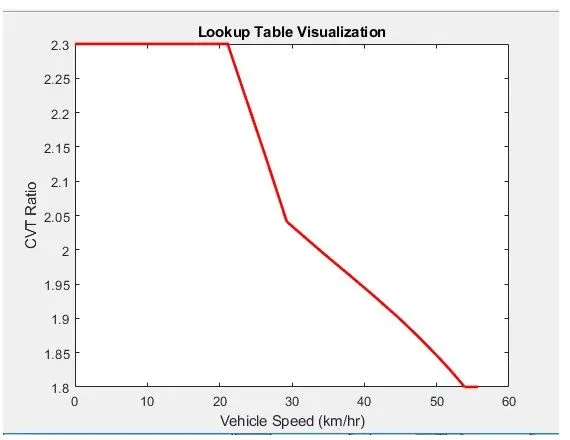
by using look up table: its assigned as input to CVT instead of giving CVT ratio.
code for look up table - program in matlab.
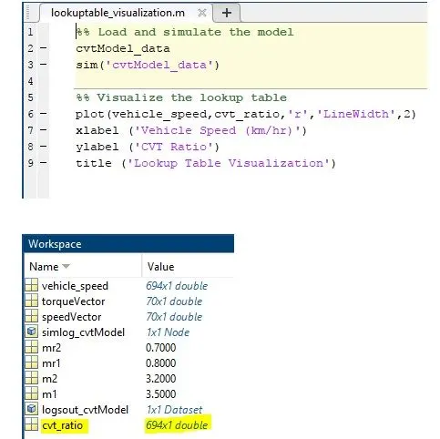
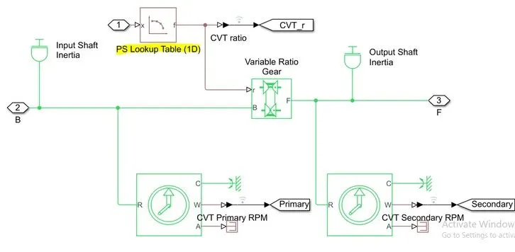
Giving input to CVT using look up table :
After creating look up data give data as input to CVT.
Result:look up table visulization plot:
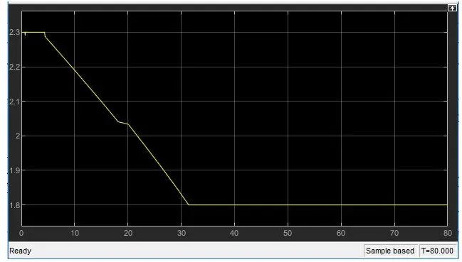
CVT ratio plot::
look up table data
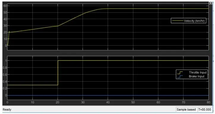
Vechicle speed plot: in this brake input is 0 and throotlr input is 0.3 for 20 sec, velocity will reach at 20 and by incresing throttle input value to 1 , then velocity value will increase and it reaches the maximum velocity.
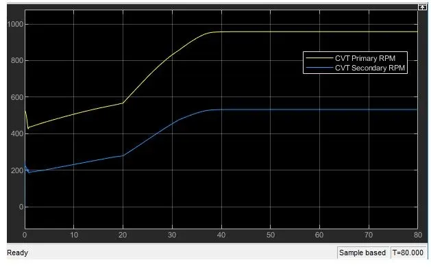
CVT shaft speed plot:in this primary pully go inward and secondary pully go outward it will lead to over drive,primaary pully radius increase and secondary pulley radious decreses, so speed of primary pulley is greater than secondary pully.
Engine Speed:here brake input is 0 and throttle input is 0.3 for 20 sec. engine speed will decraes at beggining because of incresing gear ratio whichnis increase torque ,and by increasing the throttle input value to 1, then engine speed value is increse and it reaches at maximum speed.
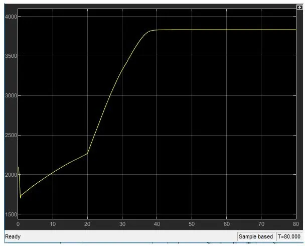
Case 2:
ATV with CVT with dashboard using look up table:
in above simulink model PRPM gauge ,Brake input gauge ,throttle input gauge and velocity gauge is connected in dash board brake input is 0 , throttle input is 0.3 for initial condition to run the simulstion,by using look up table: its assigned as input to CVT instead of giving CVT ratio.
Result:
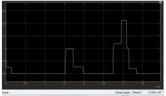
CVT ratio plot:
cvt ratio will vary by changing the throttle gauge ,if throttle value increses CVT Ratio decreses and vicde versa.
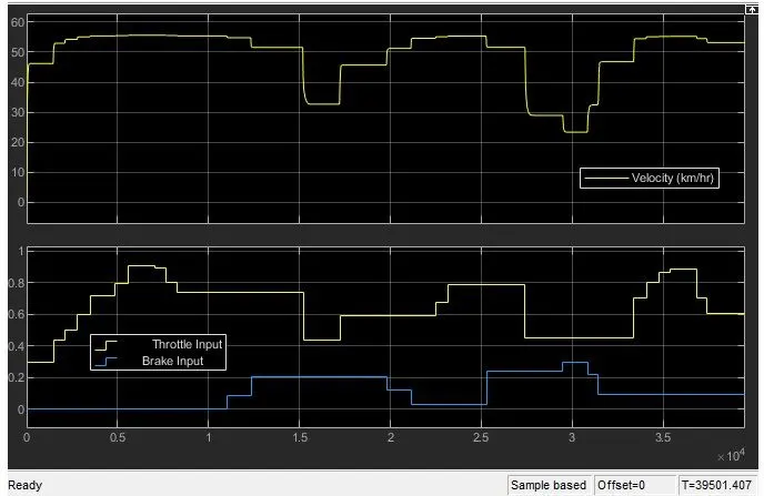
vehicle speed plot:
By incresong the throttle input value ,increse the velocity and by incresong the brake input value it will decrese the velocity.
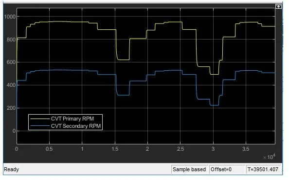
CVT Shaft speed plot:
by increase the throttle input value ,it will increase the RPM of the primary and secondary pulley and by incresing the break input value it will decrese the rpm of primary and secondary pulley.
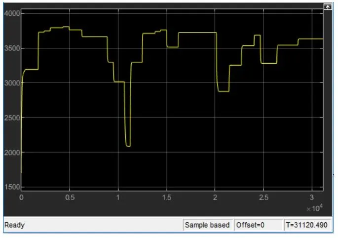
Engine Speed plot:
by increase the throttle input value ,it will increase the engine speed,by incresing the break input value it will decrese engine speed.
Conclusion:
System level simulation of an BAJA ALL terrain vechicle without look up table and with look up table are done and results are plotted.