Project
Objective :
- Performing Simulation and analysis of the CVTBAJAA Model for the three different input parameters .
- Analysis of the results .
- Analysis of the Various parametres and the input to model , how that affects the models design .
- This Simulation or Model will help to determine the correct and accurate design parametres for the designing the actual model of tthe CVT BAJAA.
Case Study_1 :
CVT Model with constant Brake and Throttle Input :
Simulink Model :
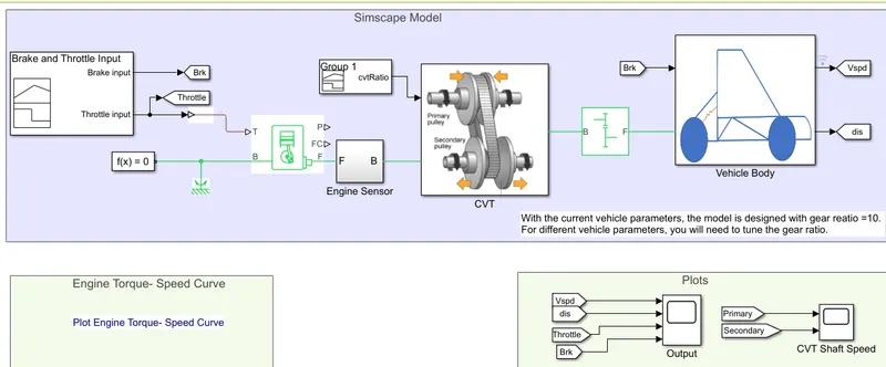
Simulink and Simscape Block required :
- Signal builder
- Simulink-PS converter
- Generic Engine
- RPM Sensors
- Scopes
- Variable Ratio Gear
- Shaft Inertia
- Simple Gear
- Vehicle Body
- Rotaional Reference and
- from-to connections
Construction :
- Signal Builder is used to provide the initial Brake and the Throttle input
- This Signal builder is connected to the generic enigine to Throttle port ( T ).
- The Engines Block ( B ) port is connected to the rotatinal reference .
- Output of the engine , Crank shaft Port ( F ) is connected to the Engine Sensor .
- Then Connected to the CVT Subsytem .
- Followd by the To the simple gear.
- Thhis Simple Gear is then Attached to the Vahicle Body .
- All the sensors are used to the respective Loaction to analys the input and outputs of the CVT model .
Working Of the Simulink Model :
- This Model is analysed for the Constatnt input parametres of Brake and Throttle Input .
- The Signal Builder is used to provide the initial constant input value of the brake and the throttle . The Values are for Brake Input is 0 units and for Throotle input is O.5 units , which can be seen below as ,
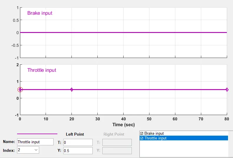
- This Signal Builder's Input values are provided to the Generic Engine To Throttle port ( T ) .
- To measure the input values there is scope attached .
- This input values are the Simulink Signals so, in order to convert the This simulink signal to the Simscape signal , the Simulink to physical converter block is used .
- This Generic Engine takes the throttle valuues and the generate the speed accourding to it , here we can measures the engine power output and Fuel consumption rate throgh the P and FC port of the engine respectively .
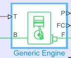
- The Block Port is attached to the rotational reference and the output port F is connected to the Engine sensor which uses the Rotations produced by the engine ( RPM ) throgh the RPM sensor and which are displayed on scope .
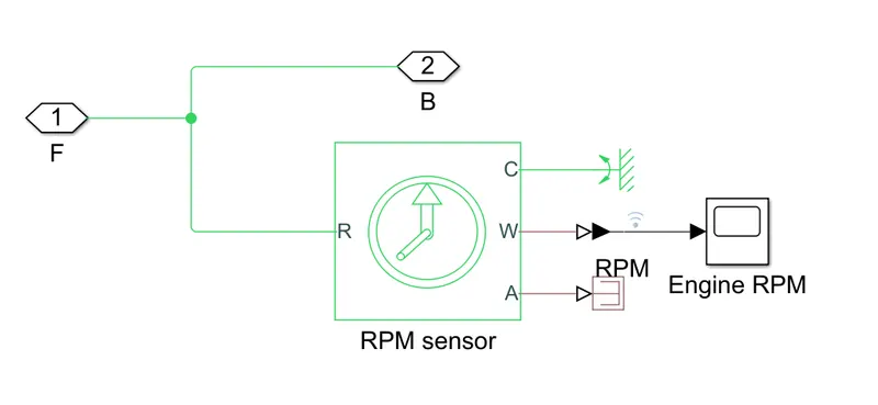
- Now the Engines Crankshaft speed of the Generic engine is prvided to the CVT Subsystem .
- To achive the variable transmission , inside the CVT subsystem the variable Ratio Gear is used to get the variable speed drive the vehicle . For that the Two shaft ineartia and the RPM sensors are provided at the input and output shaft of the Variable Ratio Gear .
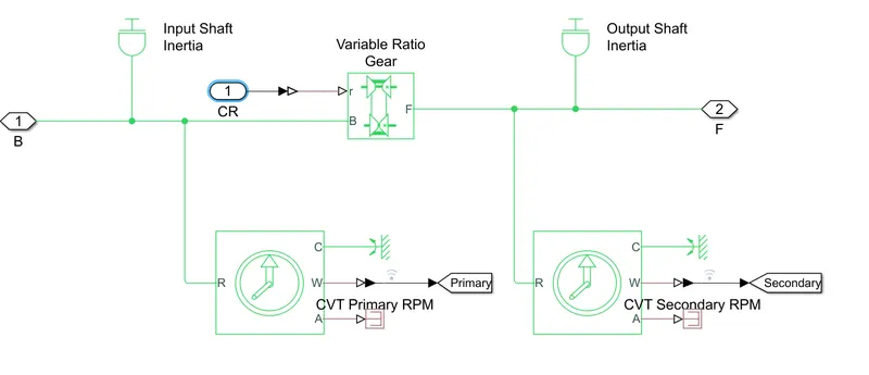
- In order to get Variable Speed Ratio , here the priviously recorded data is used in signal builder , which are given to the variable Ratio Gear as an input .
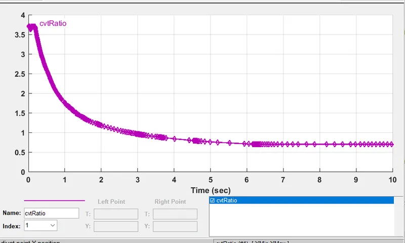
- The Simple Gear box is used to provide the Fixed-Gear Ratio of the value 10 .
- To accomplise the losses happing in the Variale Ratio Gear , here simple Gear is used to add the losses like Meshing Losses , Backlashand the Viscous Bearing Losses .
- Output of the Simple gear box with the lowered speed from the CVT is Given as input to the vehicle body .
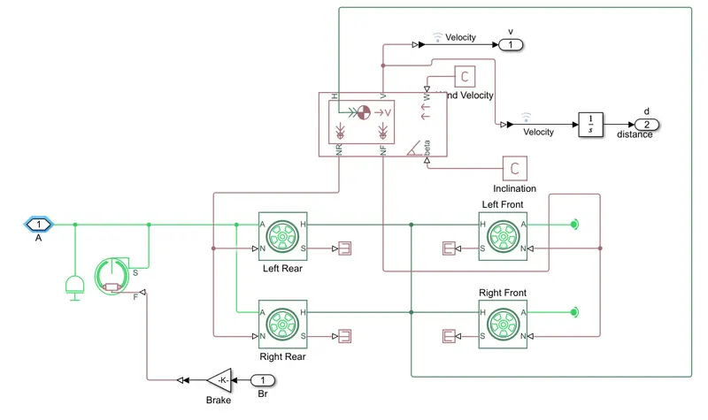
- Here the Tires Translational conserving port for the hub ( H ) through which the trust developed by the tyre is transfered to vehicle are connected to the H port of the Vehicle body of the all 4 wheels .
- The A port ( Mechanical Rotational port ) for the wheel Axel are connected to input from the Simple gear Box .
- and other Port Of the wheels like N port are connected to the Vehicle body's front tire and the Rear tires port .
- Constant Air velocity is provided by the constant value using constant block .
- Some angle inclination is provided using the constant value .
Results :
- The Model is then made to run for getting the outputs over the Given and provided conditions .
- The Various resulted Plots are can be seen below .
- For the input of Brake and the throttle , the Velocity and the Distance covered by the vehicle can be seen below plot .
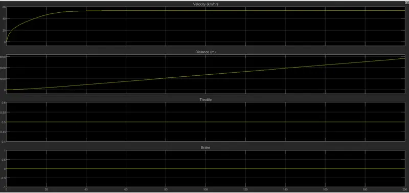
- Here we can see that the for the constant initial throttle 0.5 value , the speed is drastically increases and then becomes constant after some time .
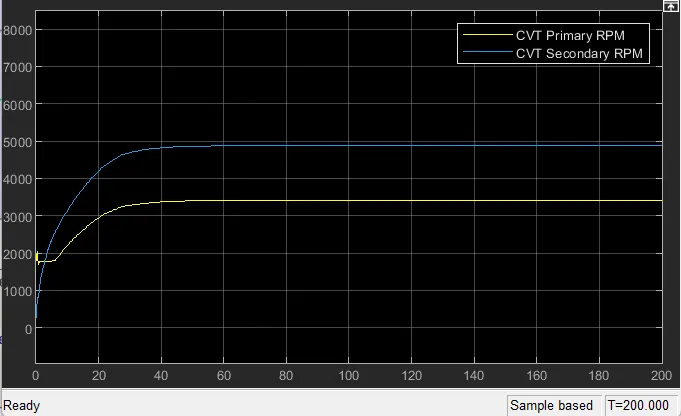
- And the Primary and Secondary speed of the CVT Shaft we got as below ,
Case Study_2 :
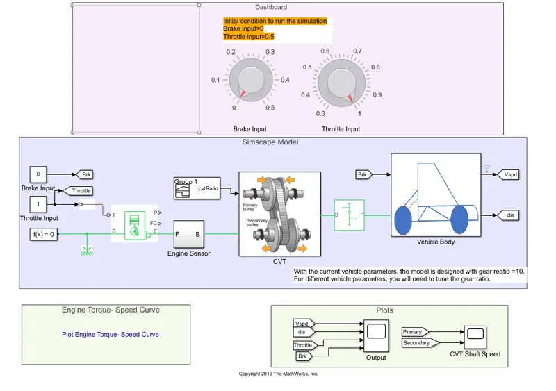
CVT Model with Veriable Brake and Throttle Input :
Simulink and Simscape Block required :
- Knobs for dashboard
- signal builder
- Simulink-PS converter
- Generic Engine
- RPM Sensors
- Scopes
- Variable Ratio Gear
- Shaft Inertia
- Simple Gear
- Vehicle Body
- Rotaional Reference and
- from-to connections
Construction :
- Here Knob for various input value is used to provide the initial Brake and the Throttle input in the Dashboard .
- This Signal builder is connected to the generic enigine to Throttle port ( T ).
- The Engines Block ( B ) port is connected to the rotatinal reference .
- Output of the engine , Crank shaft Port ( F ) is connected to the Engine Sensor .
- Then Connected to the CVT Subsytem .
- Followd by the To the simple gear.
- Thhis Simple Gear is then Attached to the Vahicle Body .
- All the sensors are used to the respective Loaction to analys the input and outputs of the CVT model
Working Of the Simulink Model :
- This Model is analysed for the Constatnt input parametres of Brake and Throttle Input .
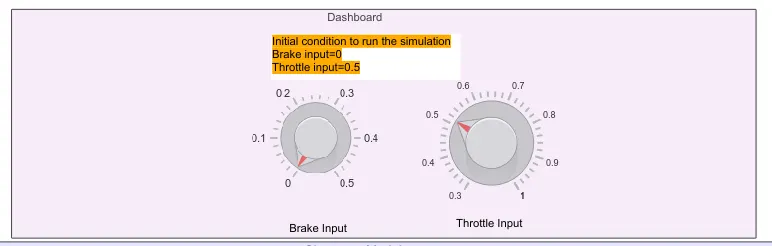
- The Knob is used to provide the various input value of the brake and the throttle between 0 & 1 . The Values are for Brake Input is 0 units and for Throotle input is O.5 units , which can be seen below as ,
- This various Input values from knob are provided to the Generic Engine To Throttle port ( T ) .
- To measure the input values there is scope attached .
- This input values are the Simulink Signals so, in order to convert the This simulink signal to the Simscape signal , the Simulink to physical converter block is used .
- This Generic Engine takes the throttle valuues and the generate the speed accourding to it , here we can measures the engine power output and Fuel consumption rate throgh the P and FC port of the engine respectively .
- The Block Port is attached to the rotational reference and the output port F is connected to the Engine sensor which uses the Rotations produced by the engine ( RPM ) throgh the RPM sensor and which are displayed on scope .
- Now the Engines Crankshaft speed of the Generic engine is prvided to the CVT Subsystem .
- To achive the variable transmission , inside the CVT subsystem the variable Ratio Gear is used to get the variable speed drive the vehicle . For that the Two shaft ineartia and the RPM sensors are provided at the input and output shaft of the Variable Ratio Gear .
- In order to get Variable Speed Ratio , here the priviously recorded data is used in signal builder , which are given to the variable Ratio Gear as an input .
- The Simple Gear box is used to provide the Fixed-Gear Ratio of the value 10 .
- To accomplise the losses happing in the Variale Ratio Gear , here simple Gear is used to add the losses like Meshing Losses , Backlashand the Viscous Bearing Losses .
- Output of the Simple gear box with the lowered speed from the CVT is Given as input to the vehicle body .
- Here the Tires Translational conserving port for the hub ( H ) through which the trust developed by the tyre is transfered to vehicle are connected to the H port of the Vehicle body of the all 4 wheels .
- The A port ( Mechanical Rotational port ) for the wheel Axel are connected to input from the Simple gear Box .
- and other Port Of the wheels like N port are connected to the Vehicle body's front tire and the Rear tires port .
- Constant Air velocity is provided by the constant value using constant block .
- The Road angle inclination is provided using the constant value .
Results :
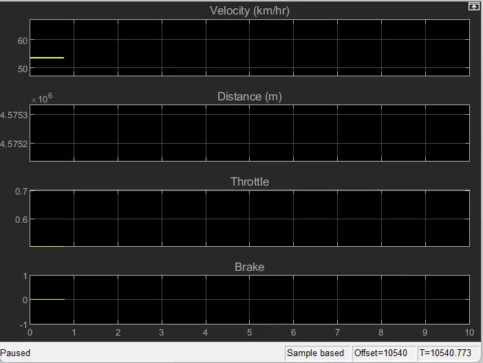
- The velocity and the Distance against the Initial condition . i.e. Throttle = 0.5 and brake = 0 , values can be seen below ,
- Velocity and Distance against Throttle at 0.8 and the Brake = 0 ,
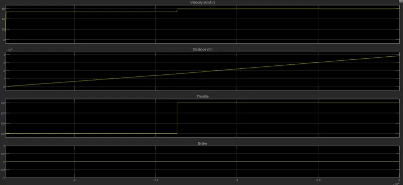
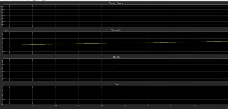
- Here we can clearly see that the as throttle increases the Speed also goes on increasing .
- Now velocity and Distance against the Throttle at 1 and the Brake at 0 ,
Case Study_3 :
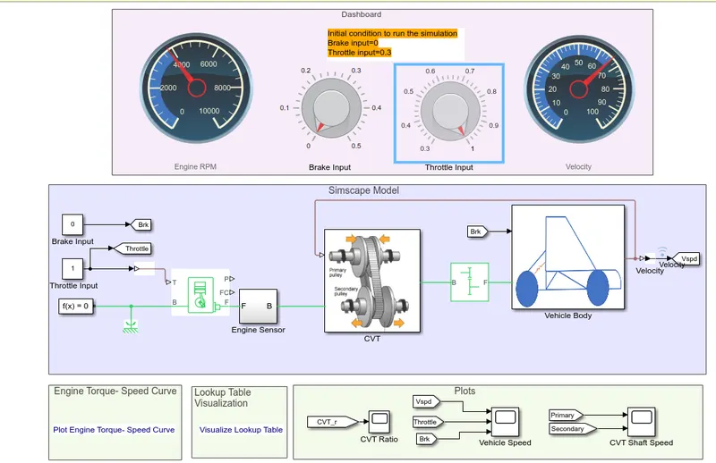
CVT Model with Veriable Brake and Throttle Input and the Mapped feedback from Vehicle Speed to The CVT :
In this system the feedback loop is created to get the required CVT ratio
Simulink and Simscape Block required :
- Knobs for dashboard
- signal builder
- Simulink-PS converter
- Generic Engine
- RPM Sensors
- Scopes
- Variable Ratio Gear
- Shaft Inertia
- Simple Gear
- Vehicle Body
- Rotaional Reference and
- from-to connections
Construction :
- Here Knob for various input value is used to provide the initial Brake and the Throttle input in the Dashboard .
- This Signal builder is connected to the generic enigine to Throttle port ( T ).
- The Engines Block ( B ) port is connected to the rotatinal reference .
- Output of the engine , Crank shaft Port ( F ) is connected to the Engine Sensor .
- Then Connected to the CVT Subsytem .
- Followd by the To the simple gear.
- Thhis Simple Gear is then Attached to the Vahicle Body .
- All the sensors are used to the respective Loaction to analys the input and outputs of the CVT model
Working Of the Simulink Model :
- This Model is analysed for the Constatnt input parametres of Brake and Throttle Input .
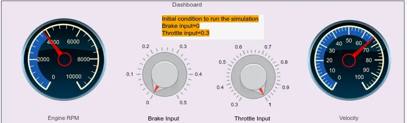
- The Knob is used to provide the various input value of the brake and the throttle between 0 & 1 . The Values are for Brake Input is 0 units and for Throotle input is O.3 units , which can be seen below as ,
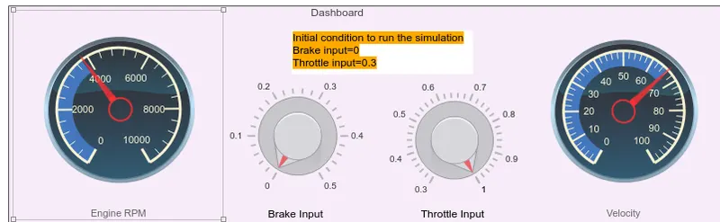
- This various Input values from knob are provided to the Generic Engine To Throttle port ( T ) .
- To measure the input values there is scope attached .
- This input values are the Simulink Signals so, in order to convert the This simulink signal to the Simscape signal , the Simulink to physical converter block is used .
- This Generic Engine takes the throttle valuues and the generate the speed accourding to it , here we can measures the engine power output and Fuel consumption rate throgh the P and FC port of the engine respectively .
- The Block Port is attached to the rotational reference and the output port F is connected to the Engine sensor which uses the Rotations produced by the engine ( RPM ) throgh the RPM sensor and which are displayed on scope .
- Now the Engines Crankshaft speed of the Generic engine is prvided to the CVT Subsystem .
- To achive the variable transmission , inside the CVT subsystem the variable Ratio Gear is used to get the variable speed drive the vehicle . For that the Two shaft ineartia and the RPM sensors are provided at the input and output shaft of the Variable Ratio Gear .
- In order to get Variable Speed Ratio , here the feedback loop is created , in which the vehicle velocity is measured and the is fed to the CVT through the Lookup table which campaire the velocity output values with the values in CVTr variables from base workspace and adjust the required Gear ratio , which are given to the variable Ratio Gear as an input .
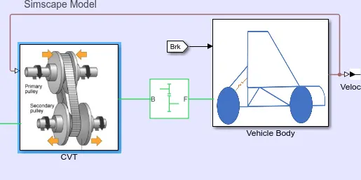
- The Simple Gear box is used to provide the Fixed-Gear Ratio of the value 10 .
- To accomplise the losses happing in the Variale Ratio Gear , here simple Gear is used to add the losses like Meshing Losses , Backlashand the Viscous Bearing Losses .
- Output of the Simple gear box with the lowered speed from the CVT is Given as input to the vehicle body .
- Here the Tires Translational conserving port for the hub ( H ) through which the trust developed by the tyre is transfered to vehicle are connected to the H port of the Vehicle body of the all 4 wheels .
- The A port ( Mechanical Rotational port ) for the wheel Axel are connected to input from the Simple gear Box .
- and other Port Of the wheels like N port are connected to the Vehicle body's front tire and the Rear tires port .
- Constant Air velocity is provided by the constant value using constant block .
- The Road angle inclination is provided using the constant value .
Results :
- The Velocity Vs. the initial Throttle at 0.3 units and the Brake at 0 units input .
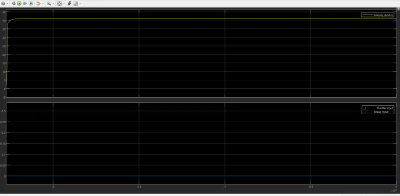
Velocity and the Engine RPM :
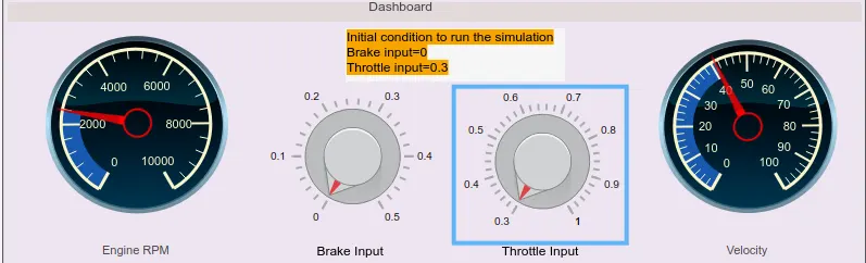
- Here we can see that the velocity increases drastically with inuitially throttle at 0.3 units from 0 to 42-43 km/hr .
- Now after some time , if we change the throttle value to 0..6 units fron knob , velocity will also goes on increasing .
- The Velocity Vs. Throttle at 0.6 units and the Brake at 0 units input .
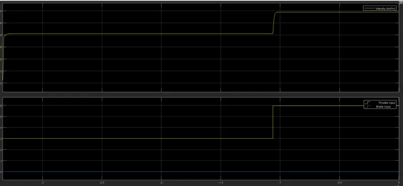
Velocity and the Engine RPM :
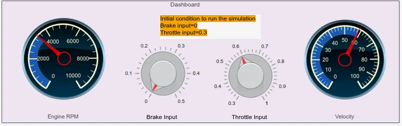
- The Velocity Vs. the initial Throttle at 0.8 units and the Brake at 0 units input .
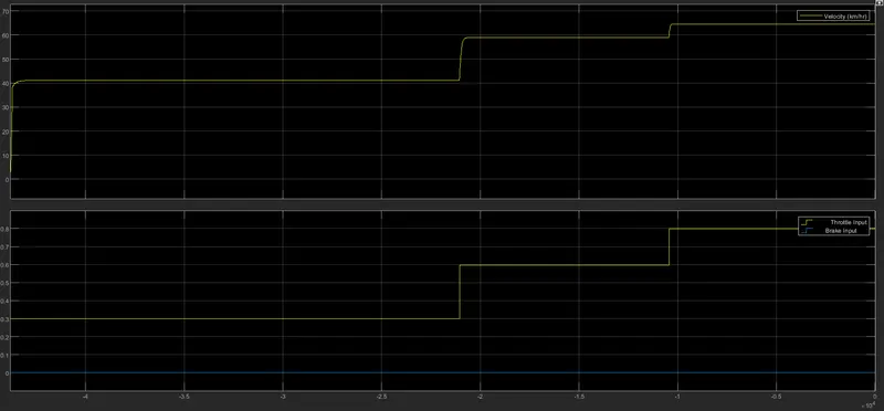
- Velocity and the Engine RPM :
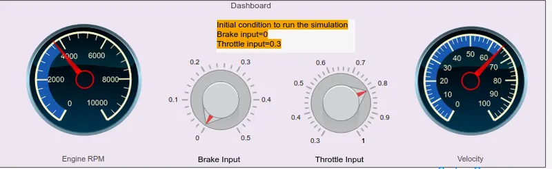
- The Velocity Vs. Throttle at 1 units and the Brake at 0 units input .
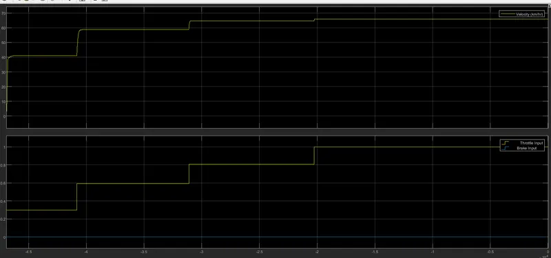
- Velocity and the Engine RPM :
Conclusion : Using the simulink we can create real condition project model and the simulation of the for the optimazation of the Model , The variour input parameters can be given and the changed also , to get required Design parameter accourding to the actual model design . On the Basis of the simulation and the input values provided , we will get idea of the vehicle behaviour puting it to different sittuation and applying various condition , to get optimazed Design of vehicle .