Project
AIM:
The main objictive of this project is to study and analyse the model baja all terrain vehicle and explaining the properties and result of that model.
BAJA :
BAJA is an event organised every year by SAE for all terrain vehicles where students from different universities get participated.
The focussing areas are transmission system,braking system, steering system,suspension system, CVT , weight of the vehicle, performance of the all-terrain vehicle. Various test are conducted for the validation of the vehicle.
Most baja vehicles are rear wheel drive.
What is CVT?:
This transmission is also called as shiftless or automatic transmission. They are used in automobiles,tractors,snowbikes,scooter etc., There are various types of cvt pulley, electrical,hydrostatic etc.,
The most widely used CVT type is pulley type.
It has two variable diameter pulleys which is connected by belt or chain depends on applications. The belt should be very stiff .
The radial thickness of the belt is a compromise between the maximum gear ratio and torque.
Hybrid Electric Vehicles(HEV) use Electric Variable Transmissions to control the contribution of power from the electric motor and internal combustion engine.
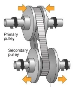
baja CVT model:
The model has the following block and its properties are,
SIGNAL BUILDER:
a) Brake input: There is no brake condition is considered so it is kept zero
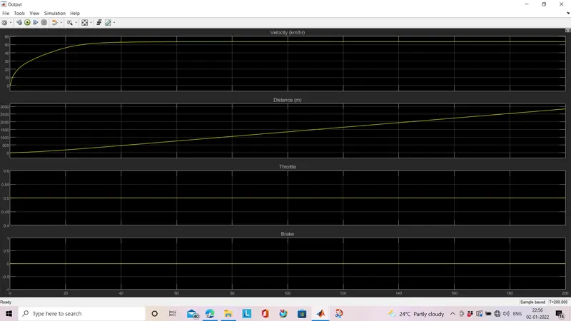
b) Throttle input: The throttle input is constant over this simulation and it is 0.5 here
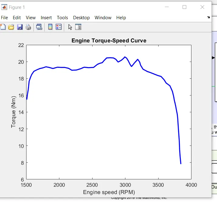
GENERIC ENGINE: Generic Engine block represents a general internal combustion engine. The block optionally supports lag due to a changing throttle only Throttle is provided as input signal. Power produced, fuel consumption rate are delivered as outputs. Engine crankshaft and Engine block are conserving ports. The speed vector and torque vector datapoints can be extracted using GRABIT file exchanger and then feed the data points in the generic engine.
ENGINE SENSOR(SUBSYSTEM):
Ideal rotational motion sensor: The motion sensor is used to calculate the rpm of the engine , since it is ideal it doesn't accounts mass,inertia . It has two rotational conserving ports and angular velocity and angular displacement as ouput. It has input from the crankshaft movement.
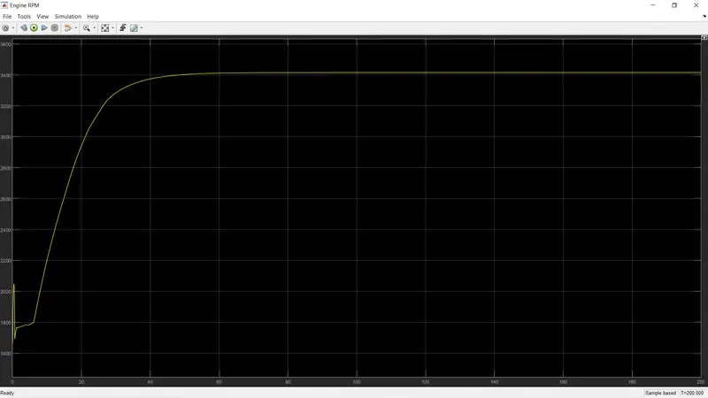
Scope is connected to the motion sensor to trace the engine rpm.
CVT SUBSYSTEM:
Variable ratio transmission: This block represents the variable ratio gearbox, where the port r represents the ratio of input to output shaft velocities. There are two models having their difference in the input to r, one is group signal builder and other is using look up table.
Inertia block: Ideal rotational inertia is represented in this block. number of graphical ports are given as per given by the user. Input shaft inertia and output shaft inertia is connected to the system.
Rotational motion sensor: Here this block is used twice one is for calculating primary rpm and other is for secondary rpm,the same is connected to the viewer block.
VEHICLE BODY SUBSYSTEM:
Vehicle body: This block represents the longitudinal motion of the vehicle body having two axles. The ports in the blocks are H,V,W NF,NR, beta. It takes account of mass, inertia, road profile. The w and beta are input ports representing the wind speed and road inclination connected to the constant block. V,NF,NR these port are representing output. NF and NR are the tires connected to the front and rear axle.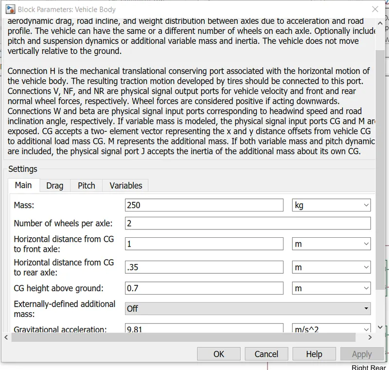
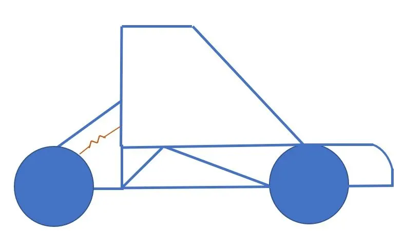
Tire (magic formula): Tire block represents four tires in the vehicle.It is a behaviour of highway tire.This block is made from tire road interaction which is the magic formula.H port is conserving port for mechanical translational port . vertical load, longitudinal load are given as parameters.N port is connected to the vehicle body.The input from the gear box is given to the rear wheel.
double shoe brake: Two pivoted rigid shoes are positioned inside or outside the drum,the rotational movement of the shaft is conserved in the s port. The actuator gives the force to the shoes and the port supply input to actuator is F.
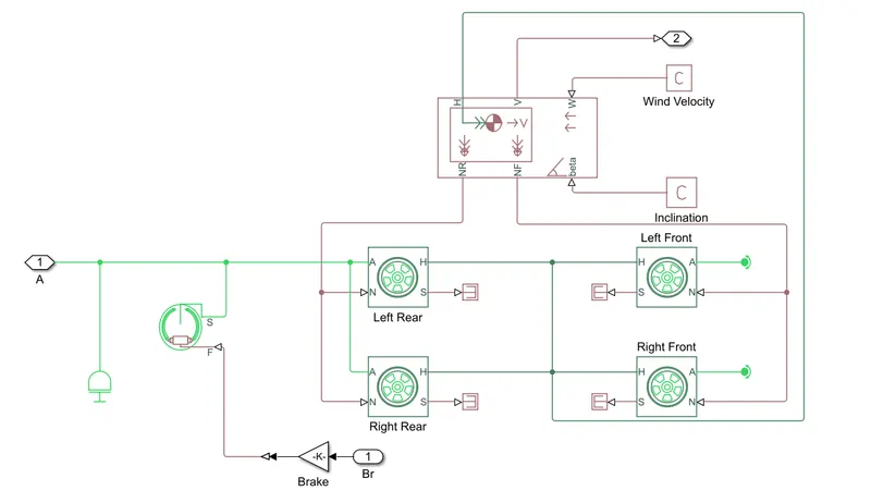
Integrator: The velocity V is connected to integrator to find the distance.
Model with fixed input:
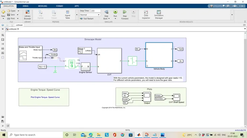
SIMPLE GEAR: It is a representation of a simple gear without considerin any inertia or mass. The user should give the ratio between base and follower as follower to base i.e it is the ratio of number of teeth in follower to number of teeth in base. The relation between the base and the follower should be mentioned(i.e the direction of output shaft related to input shaft).
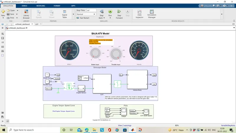
With DASHBOARD - MODEL WITH VARIABLE INPUT:
This model has a knob to adjust the throttle values , the stop time is set to infinite so that we can change the value while the simulation is running. The RPM of the engine and the velocity of the vehicle is changing continuously and can be viewed in the circular gauge block.
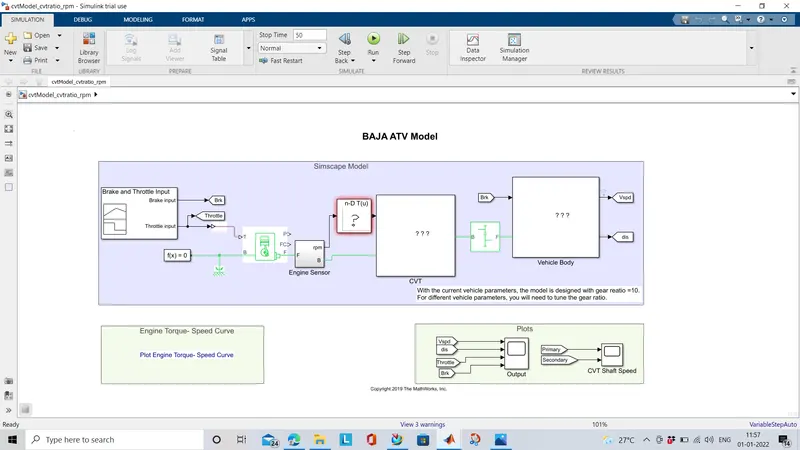
Using Look up Table:
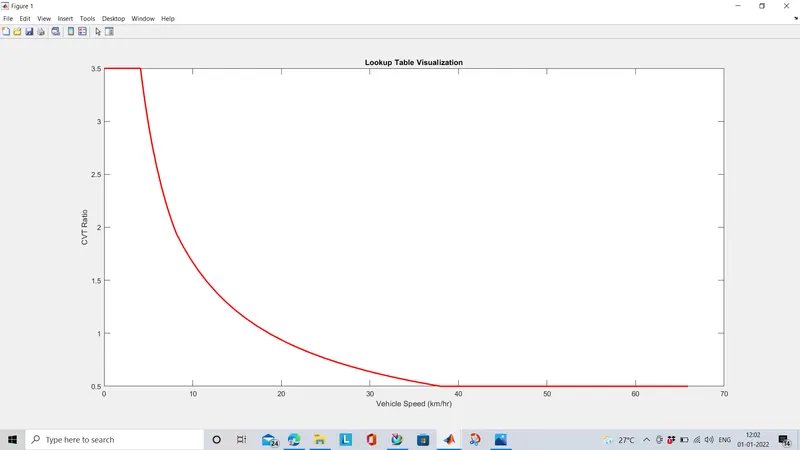
The table and breakpoints for the look up table are cvtr and speedV respectively. You have to load the datas (cvtr and speedV)in the workspace(MODEL OR BASE) to make them simulate. look up tabel is an array of data. It is used in mapping input to output. By following interpolation or extrapolation methods to calculate the values defined in table of block parameters.
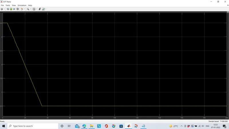
They developed a another model by feedback the velocity of vehicle body to the input of 1D lookup table and running the model gives cv ratio and velocity, distance as given below. The input throttle and brake are given as step signal.
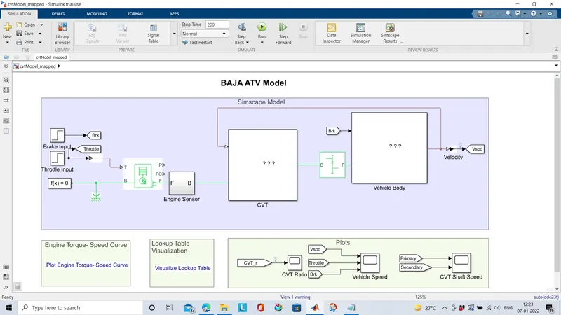
cv ratio:
output:
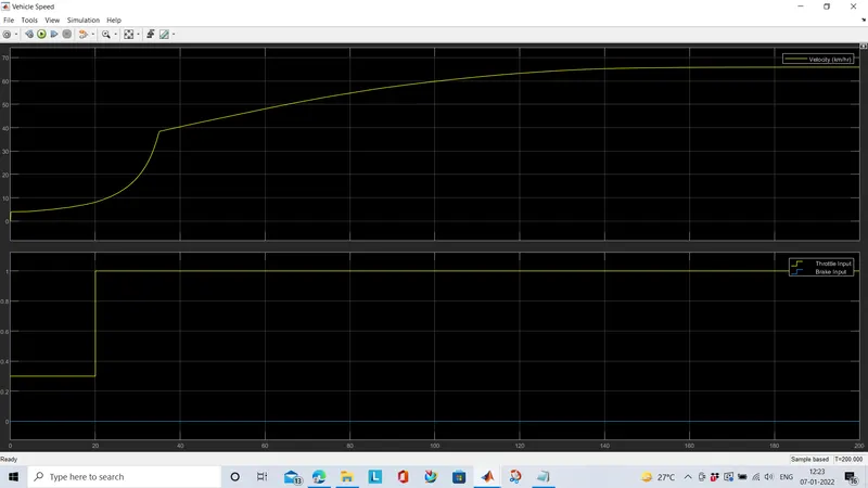
PLOTS & OBSERVATION:
The plot torque - speed is drawn using data given in the matlab workspace which is used in calculating Engine rpm in the generic engine.
The following plot is obtained when we use group signal builder as input signal for cvt ratio. The inputs to the scope block are velocity, distance, throttle, brake. We can use look up table for the input signal. The result of the velocity , engine rpm are improved in lookup table usage.
The engine RPM sensor in the rotational motion sensor is displayed using scope.
The following table shows the visualisation of lookup table for cvt ratio and velocity.
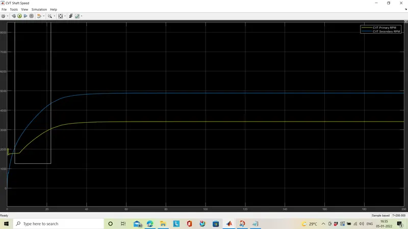
The output plot of the CVT is shown below it shows that the driven pulley is rotating faster than the drive pulley . The primary shaft is greater than the secondary one. The image below is output when using signal builder as input for cvt.
primary/secondary = 4880/3450
Data inspector gives a better understanding to the model,
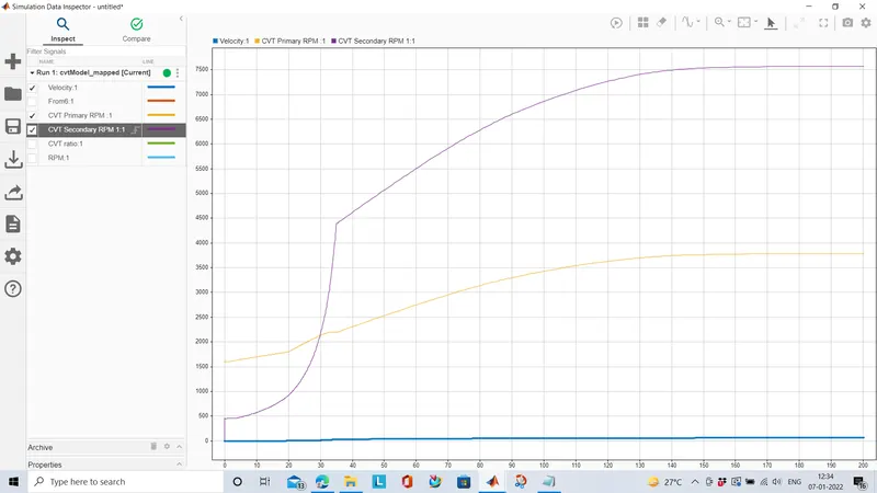
The application of lookup table in the cvt block increases both primary and secondary rpm of the continously variable transmission.
primary/ secondary =5450/3800
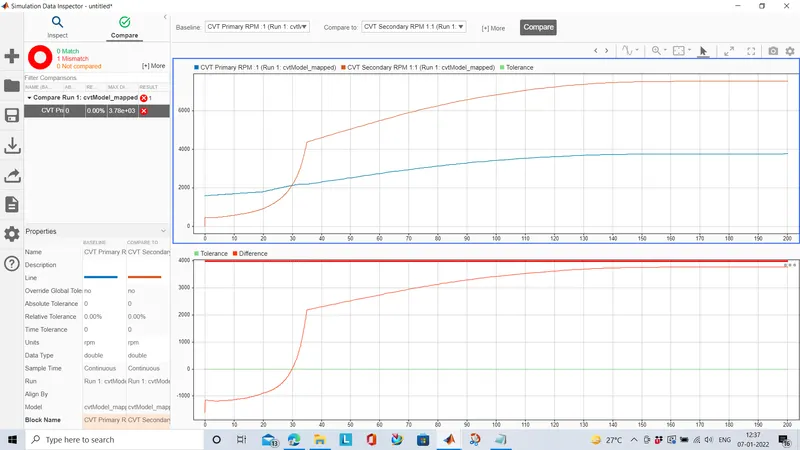
we can make use of compare tab in the data inspector to get a wider view in the simulation. we can compare signals and runs effectively.
CONCLUSION:
The baja CVT(continuously variablr transmission) model is simulated, studied, analysed for different inputs, model developed , the results are interpreted successfully.
Reference:
Modeling of a Continuously Variable Transmission (CVT) BAJA All-Terrain Vehicle (ATV) - YouTube
Continuously variable transmission - Wikipedia
matlab documentation.