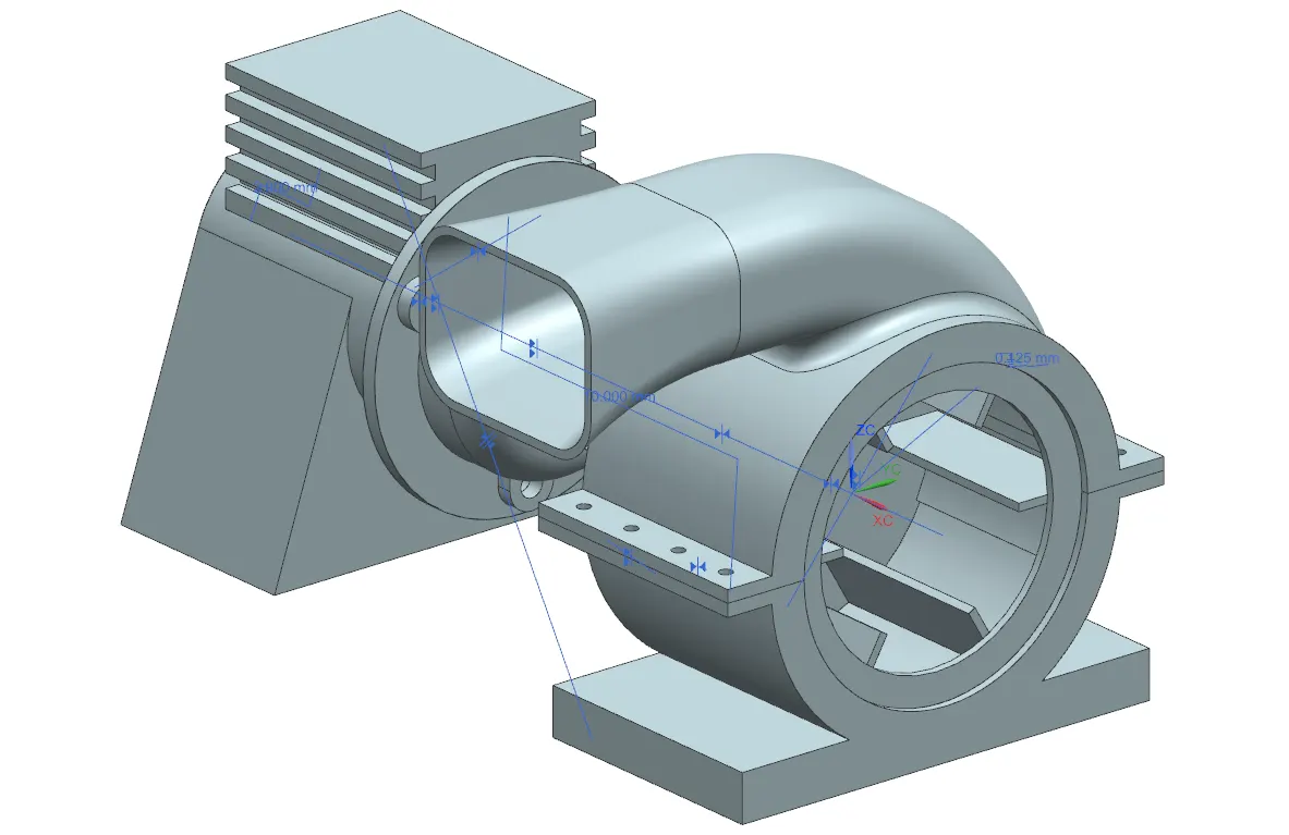
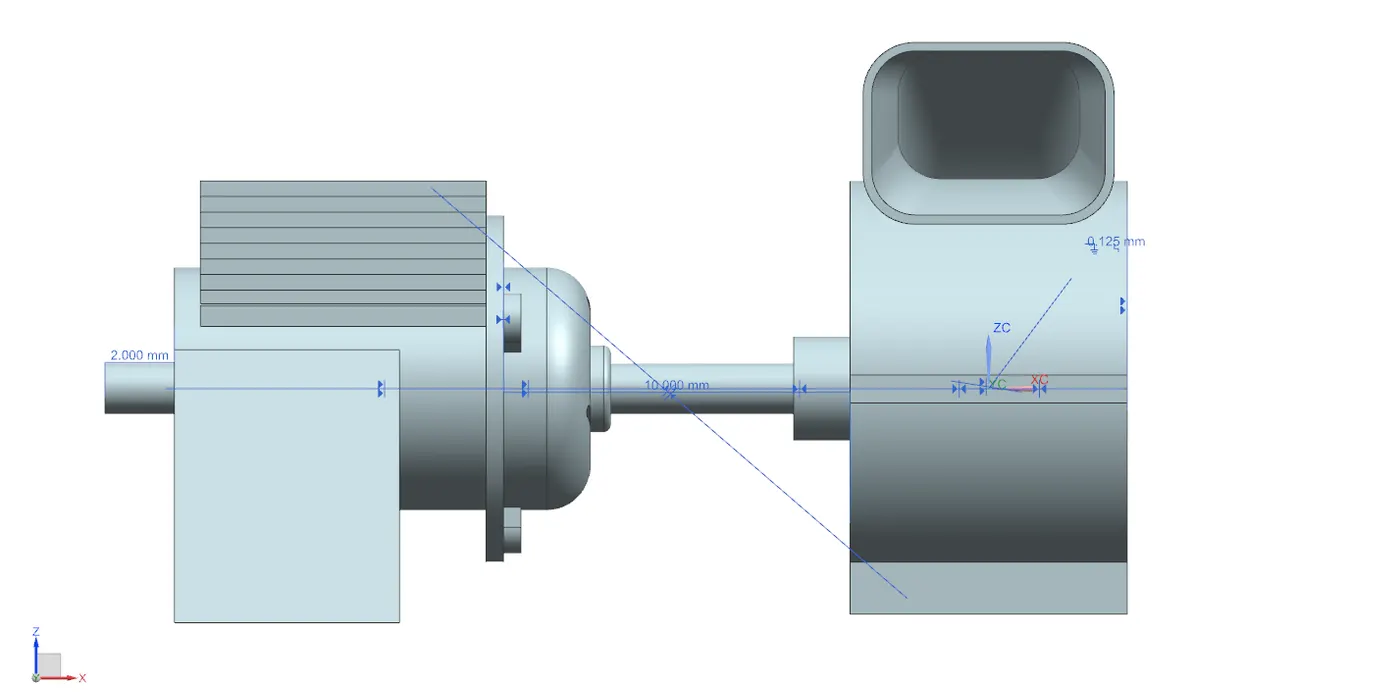
Project
**Motor Blower Assembly Instructions**
**Components:**
1. Lower Housing
2. Upper Housing
3. Motor
4. Blower
5. Shaft
6. Motor Cover
7. Assembly
**Assembly Constraints:**
- Constraints define relations between components in the assembly.
- Activate the "Assembly Constraints" command through the menu or ribbon bar.
- Constraints allow movement and rotation of objects with restrictions.
**Moving Components:**
- Activate the "Assembly Constraints" command.
- To move: Press and hold the left mouse button on the component, then drag the mouse.
- To rotate: Press and hold "Alt" on the keyboard, then press and hold the left mouse button on the component, and drag the mouse.
**Constraint Types:**
1. Touch Align
2. Concentric
3. Distance
4. Fix
5. Parallel
6. Perpendicular
7. Align/Lock
8. Fit
9. Bond
10. Center
11. Angle
**Geometry to Constrain:**
- Used to define constraint objects.
- Options change based on the selected constraint type.
- Direction of constraint can be adjusted.
MOTOR BLOWER ASSEMBLY :-
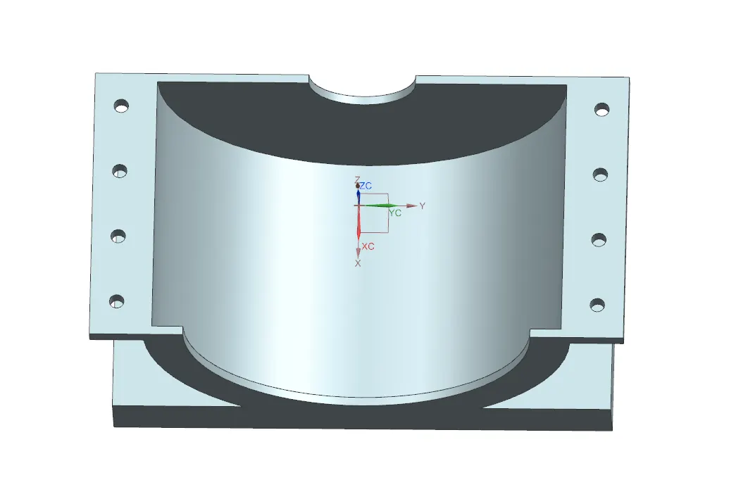
1} LOWER HOUSING :-
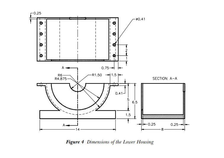
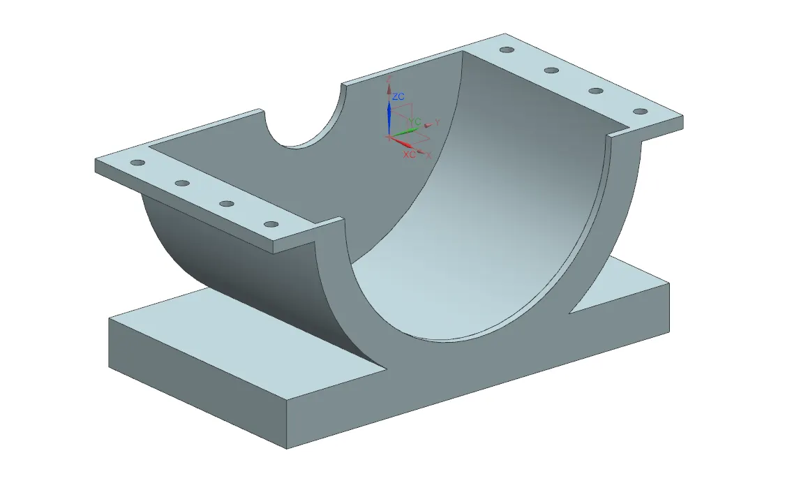
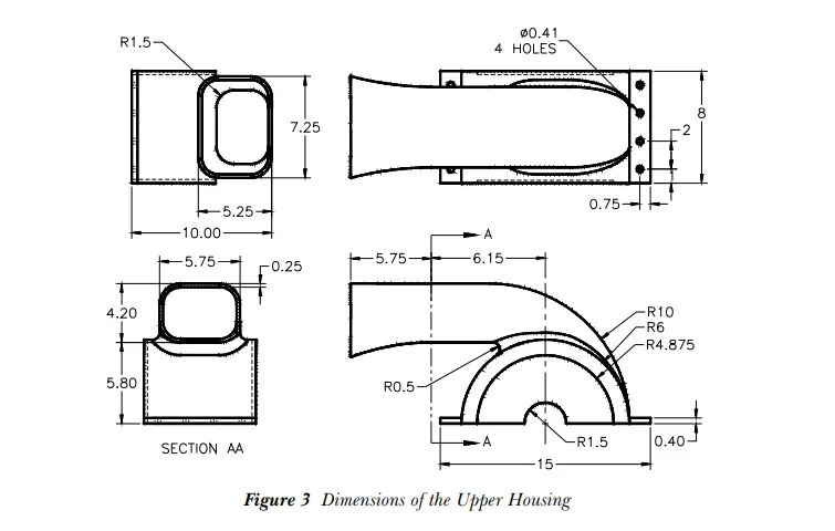
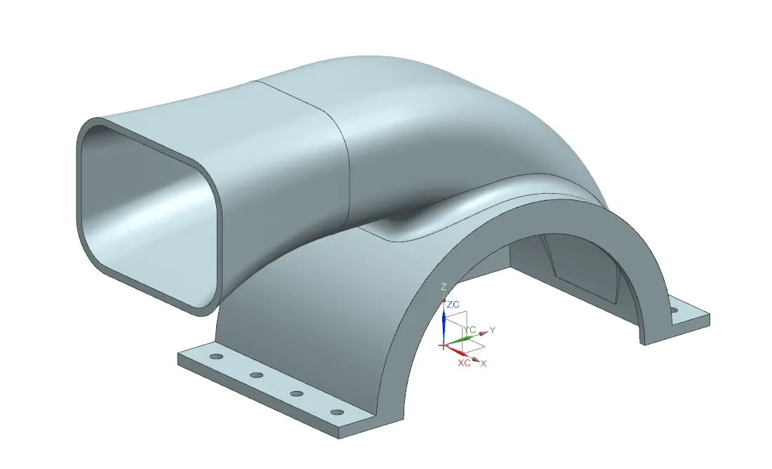
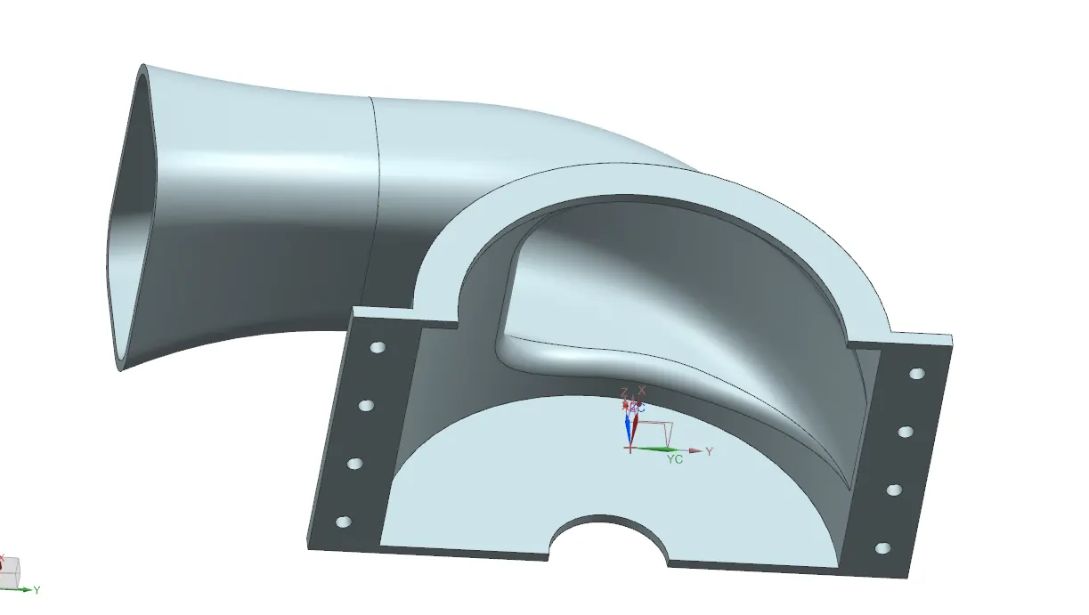
2} UPPER HOUSING :-
3} MOTOR :-
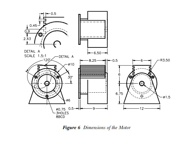
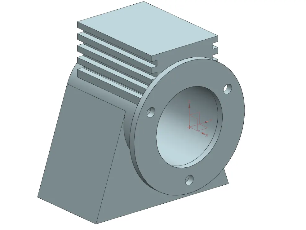
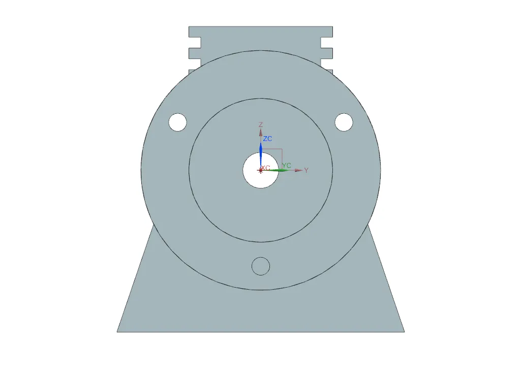
4} BLOWER :-
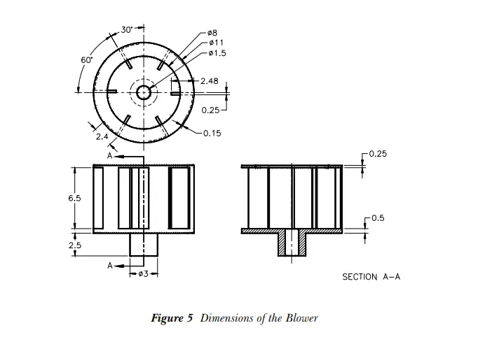
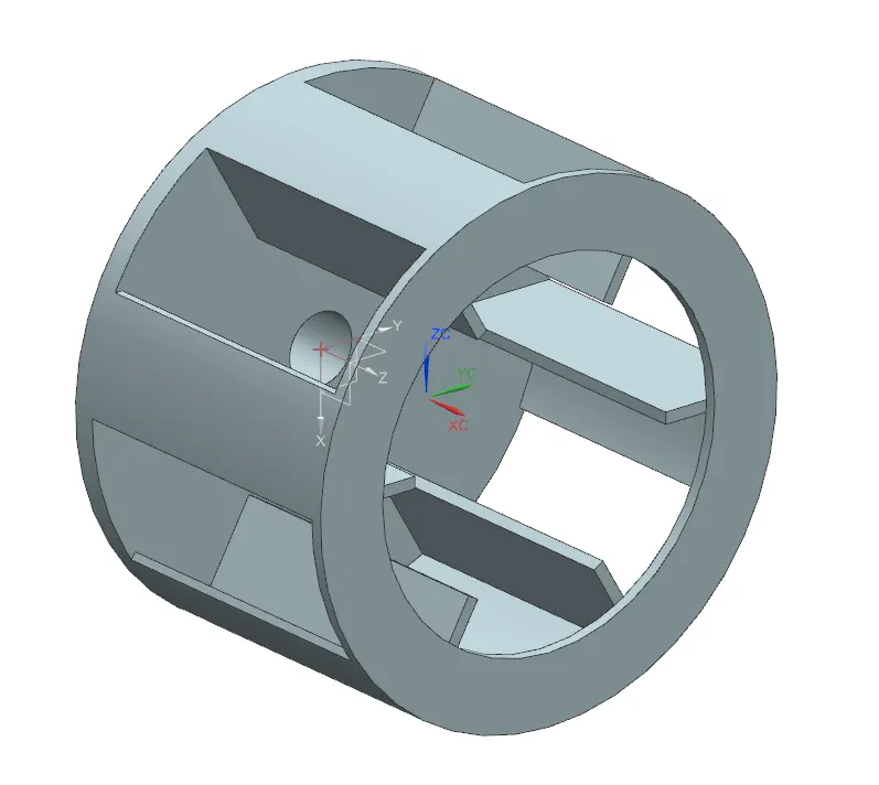
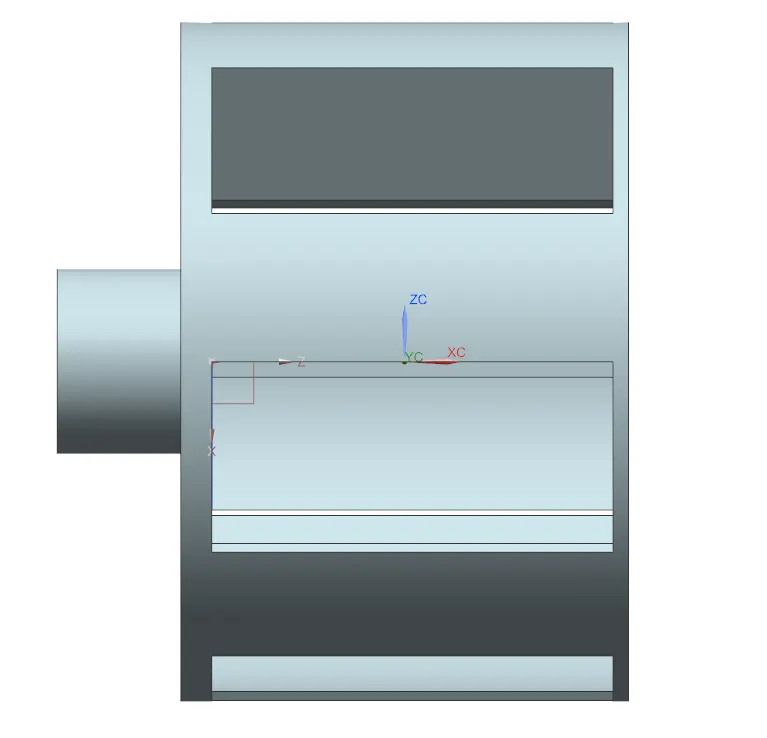
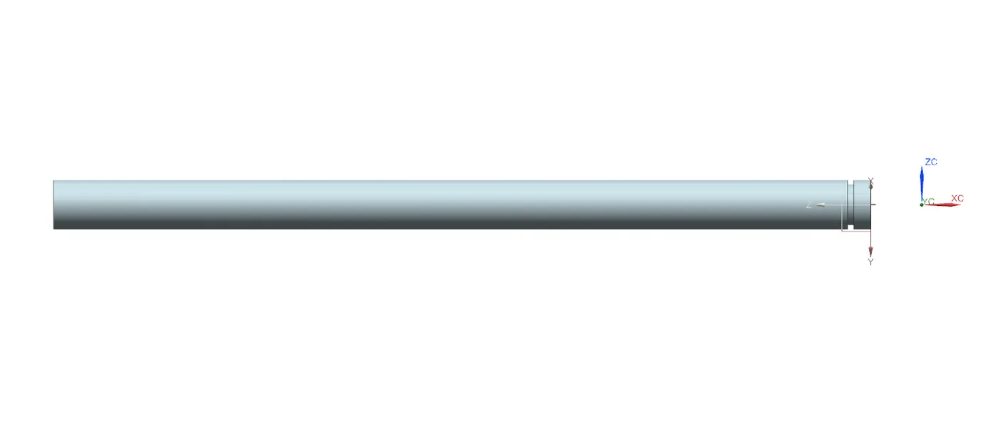
5} SHAFT :-
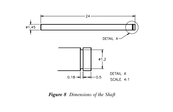
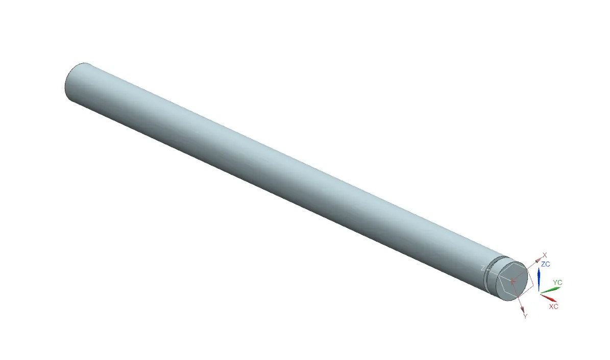
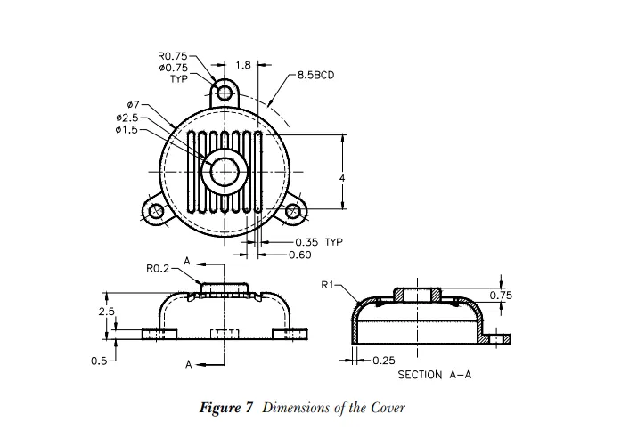
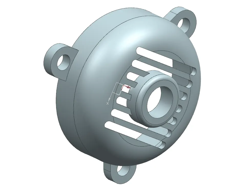
6} MOTOR COVER :-

7} ASSEMBLY :-
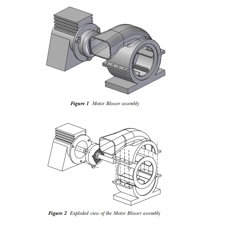
After creating all the different part files they are assembled in an assembly file by using different constraints.
assembly Constraints define relations between components in the assembly.
You can activate the “Assembly Constraints“ command by:
– Select the “Assembly Constraints“ command from “Menu=>Assemblies=>Component Position=> Assembly Constraints”
– Click on the “Assembly Constraints“ command on Home Ribbon Bar.
– Click on the “Assembly Constraints“ command on the Assemblies Ribbon Bar.
You can freely move or rotate objects on the screen when the “Assembly Constraints” command is activated due to its constraints.
- To move the component: activate the “Assembly Constraints“ command then press and hold the left mouse button on the component then drag the mouse on the screen
- To rotate the component: activate the “Assembly Constraints“ command then press and hold “alt” on the keyboard, then press and hold the left mouse button on the component and drag the mouse on the screen
Assembly Constraints pop up window :-
1} Constraint type: You can select constraint types. Also, you can deactivate constraints from the “Enabled constraint” tabs in settings.
1) Touch Align: planar or straight surfaces/edges/planes/centerlines touch or align.
2) Concentric: constraints components through circular edges.
3) Distance: specifies the distance between components' surfaces or edges.
4) Fix: fixes component on its current position
5) Parallel: defines parallel surfaces/edges/planes etc… between components.
6) Perpendicular: defines perpendicularity between surfaces/edges/planes etc… between components.
7) Align/Lock: Same as concentric but components can’t rotate around defined constraints.
8) Fit: constrains cylindrical surfaces that have the same radius.
9) Bond: defines the bond between selected components. Bonded components move together in assembly.
10) Center: centers components through selected objects. (Surfaces, planes, axis, edges, etc…)
11) Angle: defines the angle between components surfaces, edges, etc…
2} Geometry to constrain: It is used to define constraint objects. It will be active after the command started. Options changes due to the selected constraint type.
You can change the direction of the constraint by clicking the icon near the reverse last constraint.