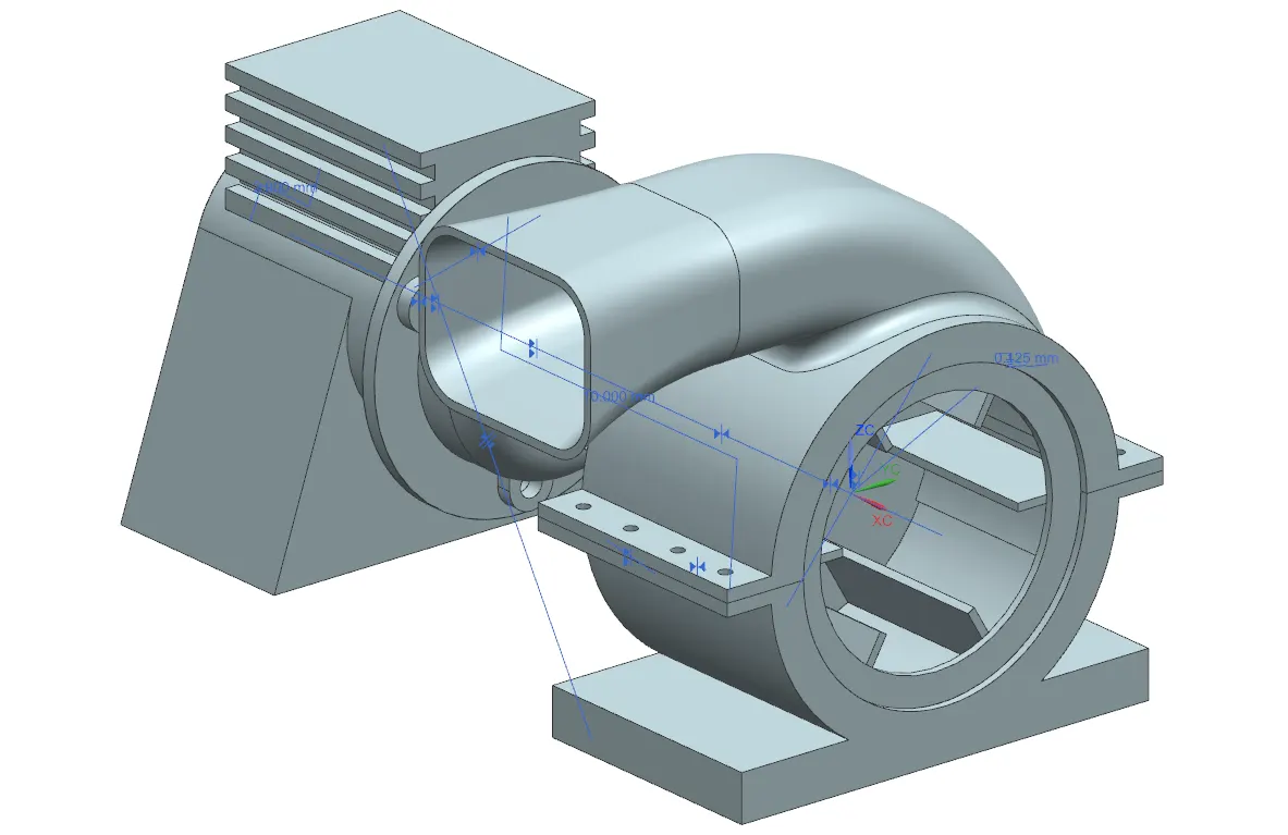
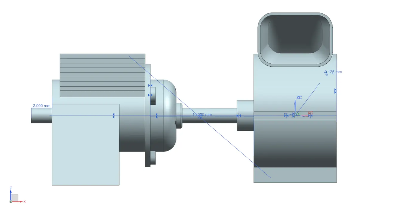
Project
WHAT IS GEOMETRIC DIMENSIONING AND TOLRANCING ?
ANS :-
Geometric Dimensioning and Tolerancing (GD&T or GD and T) is a language of symbols and standards designed and used by engineers and manufacturers to describe the shape (geometry) and size (dimensions) of a product and facilitate communication between entities working together to manufacture products. The US military created a proto-GD&T in the 1940s with the MIL-STD-8 publication (NOTE: MIL-STD-8 has since been canceled). GD&T has evolved since then and is now commonly used across the industry. ASME Y14.5 (latest revision is 2018) is now considered the standard guideline for GD&T.
TOLRANCES :-
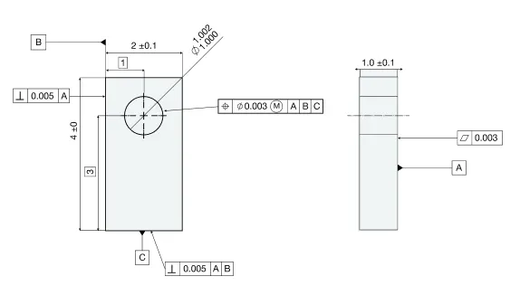
Tolerances are the ‘T’ in GD&T, and are the allowable amount of variation of a physical dimension. It’s important to keep tolerances on engineering drawings in perspective — tolerances for a given part may not be visible to the naked eye but they can have a large impact on the performance of the part or assembly.
When you look at CNC machined parts, they look flat and straight, but if you were to precisely measure every single cross-section of the part, you would find many imperfections. These variations or imperfections are allowed within the tolerance limits placed on the parts — the limits were selected with the understanding that all parts will have varying degrees of imperfection.
As a general rule, an engineer or designer should strive to keep tolerances as large as possible while still maintaining the function of the part. Small, or tight tolerances can increase costs in the manufacturing, inspection, and tooling for manufacturing parts. Tight tolerances are sometimes necessary, but it’s best to make them as loose as you can to save on those costs.
To provide some context around tolerances, let’s consider an average human hair, which is around .005 inches in diameter. In general, tolerances of +/- .005 inch are expected and achieved from today’s CNC mills. However, just because you can hold tolerances smaller than human hair doesn’t mean you need to (or that you should). Follow our guidelines for specifying CNC machining tolerances.
DATUMS AND FEATERS :-
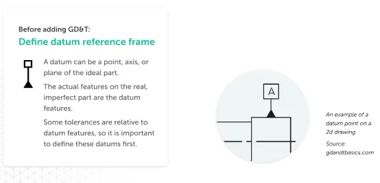
The Datum Reference Frame (DRF) in design engineering is a three-dimensional, Cartesian coordinate system against which the part’s tolerances, tolerance symbols, and geometric features are defined. It’s arguably the most important concept in GD&T and has a significant impact on the manufacturability and inspectability of a part. The DRF is the skeleton of the geometric system — it’s the frame of reference to which all referenced geometric specifications are related and the origin of all dimensions and geometric specifications related to it. A datum reference frame should mimic the assembly of the part.
A DRF establishes Six Degrees of Freedom (DOF) with three translational and three rotational. In order to design, manufacture, and verify parts, the necessary DOF must be constrained. Parts are mated to the DRF so measurements, processing, and calculations can be made.
There’s an important distinction between datums and datum features. Datums are points, axes (lines), and planes, or some combination of these components, that make up the DRF. Datum features are the actual, physical features (holes, faces, slots, etc.) on the part. They’re not perfect — they have variation. The illustrations below are provided to emphasize that Datums (left) are theoretical (perfect) and datum features (right) are real (imperfect).
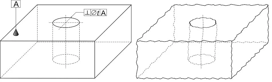
In defining a part, an engineer will identify the datum features on a part that are most important to the functional requirements of the design — usually the features that interface with other components in an assembly. Datum features referenced in a feature control frame (see Feature Control Frame) will, in an order of precedence, orient the part to the datum reference frame.
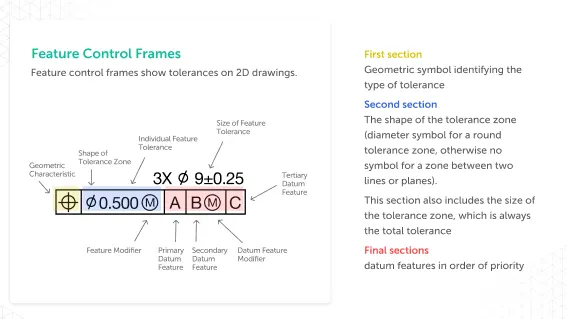
A Feature of Size refers to any geometric shape defined by dimensions like an angle, length, or height, and a Feature of Size can be defined as a datum (think a hole or post). You can use the caliper rule when determining if something can be characterized as a Feature of Size or not. If you can put the tips of a caliper around or inside of the part and they both touch surfaces of the part, then the feature is a Feature of Size.
If you have to use the probe end of the calipers to measure a feature, it’s not a feature of size. Tolerances can also be applied to features of size, and when orientation tolerances are applied to features of size, they control the angle of the axis/midplane within the tolerance zone at a basic angle to a datum.
GD AND T BASIC DIMENSIONS :-
Basic dimensions are theoretically exact numerical values used to define the form, size, orientation, or location of a part or feature. Basic dimensions are usually shown on a drawing enclosed in a box, but they can also be invoked by referencing a standard or by a note on the drawing. The CAD model itself can also be defined as basic.
Permissible variations from basic dimensions are usually defined in the GD&T feature control frame or by notes on the drawing. Any default tolerances in the title block of a drawing do not apply to basic dimensions. Often, basic dimensions are not utilized for quality inspection purposes. Basic dimensions are measured but since they don’t typically have a tolerance associated with them, they are not typically used for pass/fail criteria.
MATERIAL CONDITION MODIFERS :-
In specifying geometric controls, you often need to state that a tolerance applies to a feature at a particular feature size. The terms Maximum Material Condition (MMC) and Least Material Condition (LMC) allow an engineer to communicate that intent.
These material condition modifiers are used in a feature control frame following the feature tolerance. The application of the MMC and LMC modifiers provides additional geometric tolerance beyond the specified tolerance as the features depart from the specified condition. This is often called “bonus” tolerance.
- Maximum Material Condition (MMC) – The condition where the feature contains the maximum material with the stated limits of size. (ex: largest pin and/or smallest hole)
- Least Material Condition (LMC) – The condition where the feature contains the least material within the stated limits of size. (ex: smallest pin and/or largest hole)
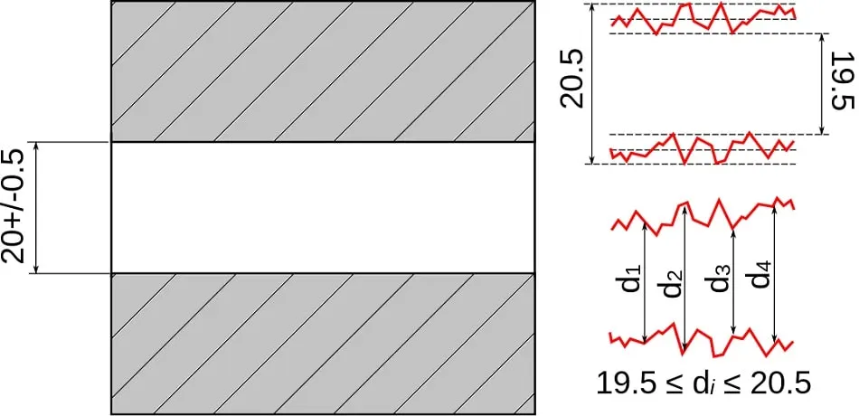
In the illustration below, the MMC of the hole is 19.5mm and the LMC of the hole is 20.5mm. As another example, consider a pattern of holes dimensioned to 20+/-0.5mm with a position tolerance of 0.6mm at MMC.
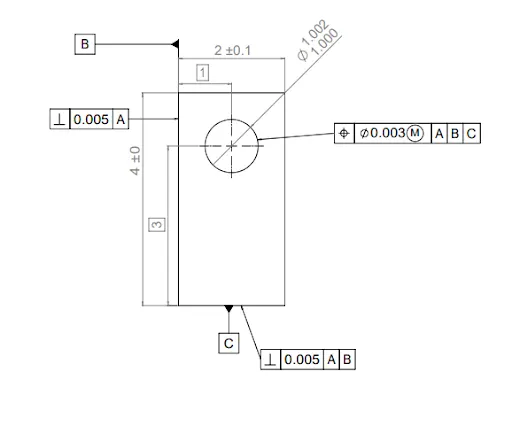
In the illustration below, the MMC of the hole is 19.5mm and the LMC of the hole is 20.5mm. The MMC for the holes is 19.5mm in diameter, and if the holes depart (get larger) from their MMC size, they are allowed additional position tolerance equal to the amount of their departure from their MMC size of 19.5mm. If the hole comes in at 20.0mm, the diameter position tolerance allowed is 1.1mm — this is how the concept of bonus tolerance works.
FEATURE CONTROL FRAME :-
The feature control frame states the requirements or instructions for the feature to which it is attached, so the feature control frame controls features (obvious, I know). Each feature control frame contains only one message, so if two messages for a feature are necessary, two feature control frames are required.
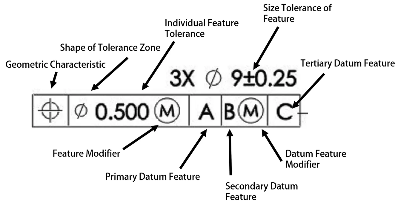
The first compartment of a feature control frame contains one of the geometric characteristic symbols. Only one of the symbols can be placed in a feature control frame. If there are two requirements for a feature, there must be two feature control frames or a composite tolerance. The symbol will specify the type of control being placed on the feature.
The second compartment of a feature control frame contains the total tolerance for the feature. The feature tolerance is always a total tolerance bound, never a plus/minus value.
If the tolerance is preceded by a diameter symbol (⌀), the tolerance zone can be pictured as a diameter or cylindrical-shaped zone — this case is often used for the position of a hole. If there is no symbol preceding the tolerance, the default tolerance zone shape is parallel planes. This case is often used to position a slot or profile of a surface.
Following the feature tolerance in the feature control frame, a material condition modifier, such as Max Material Condition (MMC) or Least Material Condition (LMC) may be specified for a feature of size, such as a hole. For a feature of size where no modifier is specified, the default modifier is RFS (Regardless of Feature Size) but this is not included in the feature control frame. For features that are not features of size, such as a plane surface, these modifiers may not be used.
All remaining compartments of the feature control frame will contain the datum feature reference(s) if they are required for the message being sent by that feature control frame. For example, if a form tolerance, such as flatness or straightness, is specified, then no datum feature reference is allowed. However, if a location tolerance like position is specified, the datum feature references are usually provided.
Technically, the alphabetical order of the datum references has no significance—the significance is their order of precedence, reading from left to right as primary, secondary, and tertiary. Often, however, Datum A will be the primary datum, followed by B and C as secondary and tertiary.
The primary is the first feature contacted (minimum contact at 3 points), the secondary feature is the second feature contacted (minimum contact at 2 points), and the tertiary is the third feature contacted (minimum contact at 1 point). Contacting the three datum features simultaneously establishes the three mutually perpendicular datum planes or the DRF. The DRF is created by Datum Simulators which are the manufacturing, processing, and inspection equipment, such as a surface plate, a collet, a three-jaw chuck, a gage pin, etc.
GD&T SYMBOLS :-
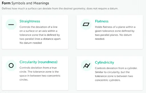
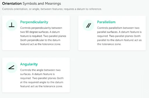
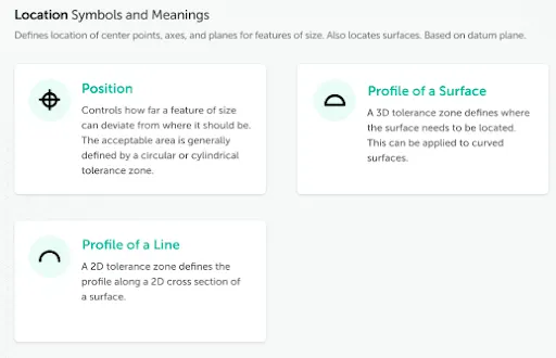
GD&T is a feature-based system where all engineered parts are composed of features. Geometric tolerances are applied to features with feature control frames, which utilize a series of symbols to describe the tolerance allowed. These Symbols or Geometric Characteristics are what most often come to mind when people think about GD&T. There are numerous GD&T characteristics and some of the most commonly used symbols that represent them are shown in the symbol “cheat sheet” below.
GD&T is feature-based, with each feature specified by different controls. GD&T symbols fall into five groups:
-
Form controls specify the shape of features, including:
-
Straightness is divided into line element straightness and axis straightness.
-
Flatness means straightness in multiple dimensions, measured between the highest and lowest points on a surface.
-
Circularity or roundness can be described as straightness bent into a circle.
-
Cylindricity is basically flatness bent into a barrel. It includes straightness, roundness, and taper, which makes it expensive to inspect.
-
-
Profile controls describe the three-dimensional tolerance zone around a surface:
-
Line Profile compares a two-dimensional cross-section to an ideal shape. The tolerance zone is defined by two offset curves unless otherwise specified.
-
Surface Profile creates through two offset surfaces between which the feature surface must fall. This is a complex control typically measured with a CMM.
-
-
Orientation controls concern dimensions that vary at angles, including:
-
Angularity is flatness at an angle to a datum and is also determined through two reference planes spaced the tolerance value apart.
-
Perpendicularity means flatness at 90 degrees to a datum. It specifies two perfect planes the feature plane must lie in between.
-
Parallelism means straightness at a distance. Parallelism for axes can be defined by defining a cylindrical tolerance zone by placing a diameter symbol in front of the tolerance value.
-
-
Location controls define feature locations using linear dimensions:
-
Position is the location of features relative to one another or to datums and is the most used control.
-
Concentricity compares the location of a feature axis to the datum axis.
-
Symmetry ensures that non-cylindrical parts are similar across a datum plane. This is a complex control typically measured with a CMM.
-
-
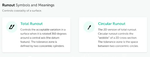
Runout controls define the amount by which a particular feature can vary with respect to the datums:
-
Circular Runout is used when there is a need to account for many different errors, such as ball-bearing mounted parts. During inspection, the part is rotated on a spindle to measure the variation or ‘wobble’ around the rotational axis.
-
Total Runout is measured on multiple points of a surface, not just describing the runout of a circular feature but of an entire surface. This controls straightness, profile, angularity, and other variations.
-
FITS :-
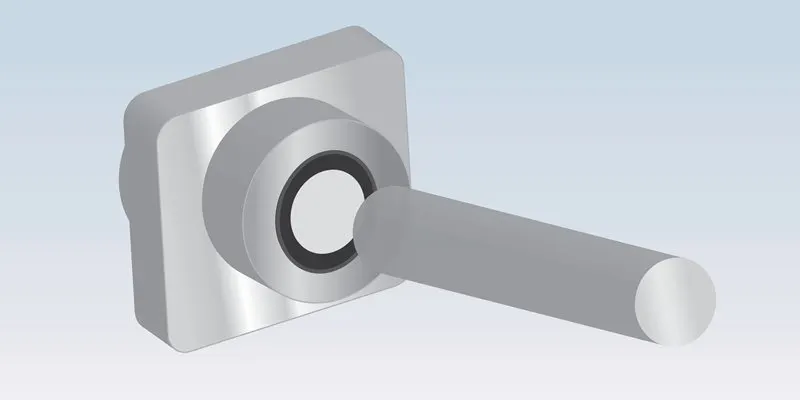
Engineered products may sometimes be parts of an assembly that must fit or slip into each other to function. As such, a fit pertains to the dimensional relationships shared by the components of an assembly or the hole with the same basic size and the shaft’s tolerance zone. It determines if the components are tight or loose.
Various options are involved in both the shaft and hole matings, and they often require the appropriate mechanical tolerances to attain the right fit. Other factors, such as ease of assembly, prevailing environmental conditions, and required precision, are fundamental to engineering components for assembly.
COMMON TYPES OF FITS :-
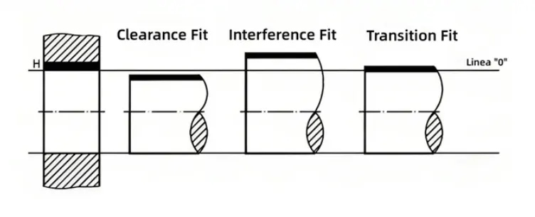
According to ISO, there are different fit types in mechanical engineering. Each fit is suitable for different circumstances. Below are these fit types:
CLEARENCE FIT :-
A clearance fit is designed for situations that require loose mating and free movement of components. Hence, they are suitable for making products in which components of their assembly must slide in and out easily. Moreover, clearance fits support relative movement between two components joined in an assembly.
The shaft diameter is usually smaller than the hole, resulting in two conditions. One is the minimum clearance in which the diameter of the shaft is higher while the hole has the minimum diameter. Secondly, a maximum clearance in which the hole bears the maximum diameter while the shaft has the minimum diameter.
INTERFERENCE FIT :-
Interference fit (also called friction fit or press fit) aids the assembly of two components by pushing them together. The fastening occurs using different mechanisms, such as substantial force for physical fitting. Also, the mechanism decides the various categories of interference fits to employ. The press-fitting of a bearing into a housing is an apt example of interference fit.
The maximum interference is the difference between the hole’s minimum size and the maximum shaft size. Similarly, the minimum interference is the difference between the minimum shaft size and the maximum size of the hole.
TRANSITION FIT :-
Transition fits provide a balance between interference fits and clearance fits. They are suitable for situations where manufacturing accuracy is a priority. For example, these fits are perfect for assembly where the mating parts must be connected with higher precision.
A good example is fitting a piston into a cylinder. The diameter of the piston is less than the cylinder bore, making a minor clearance to aid assembly while ensuring enough interference for proper fastening and stability.
Product engineers and machinists often call this fits slip or push fit. Moreover, transition fits possess minor clearance, ensuring simplified assembly while offering some interference to improve balance and stability. As such, it is evident that transition fit is the ideal engineering solution when your design requires a secure connection and easy assembly.
MOTOR BLOWER ASSEMBLY :-
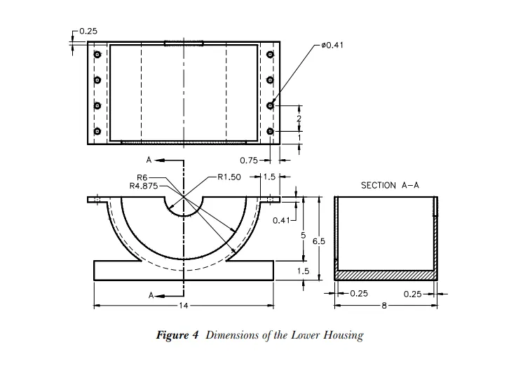
1} LOWER HOUSING :-
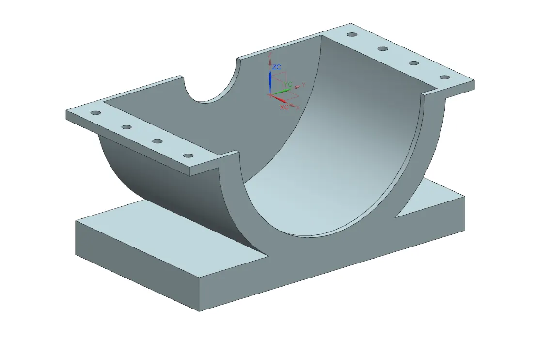
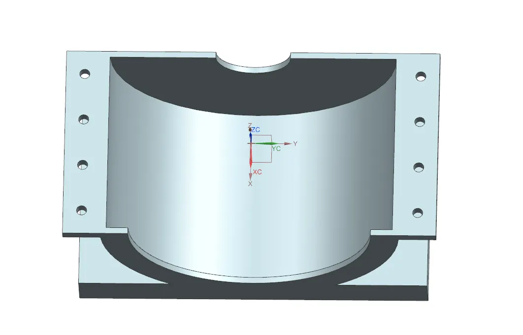
2} UPPER HOUSING :-
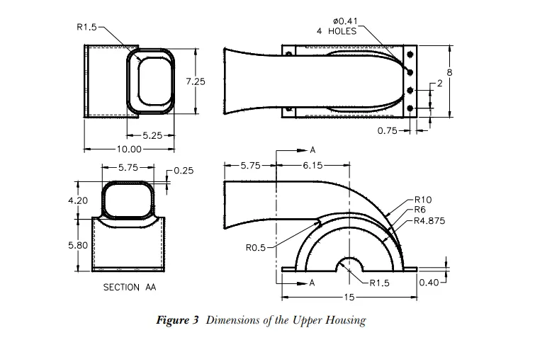
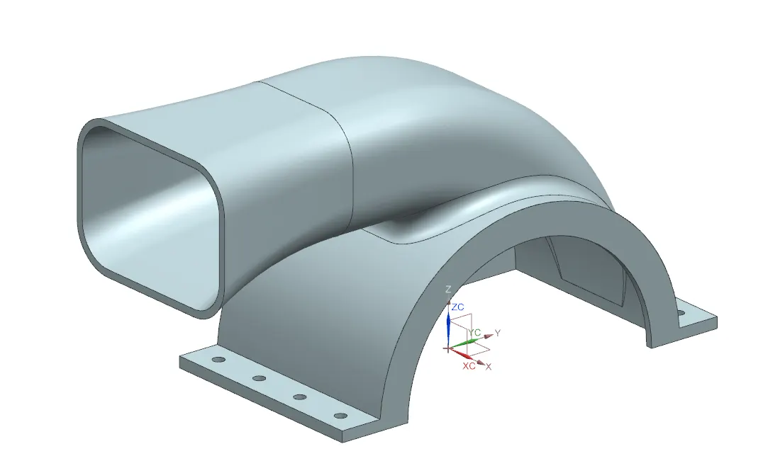
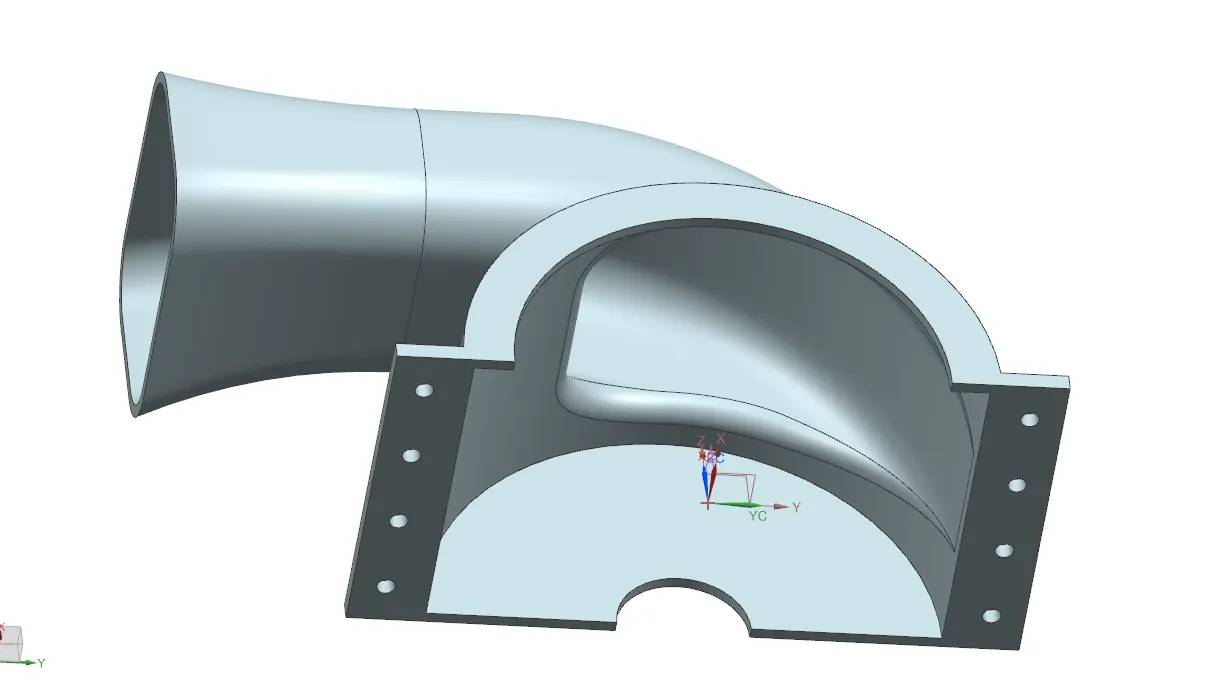
3} MOTOR :-
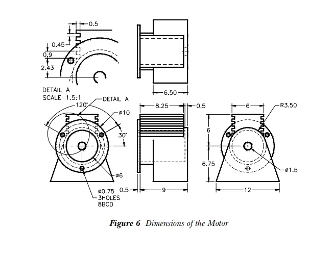
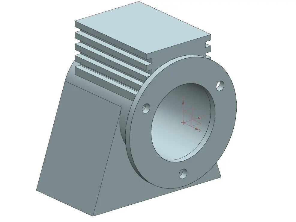
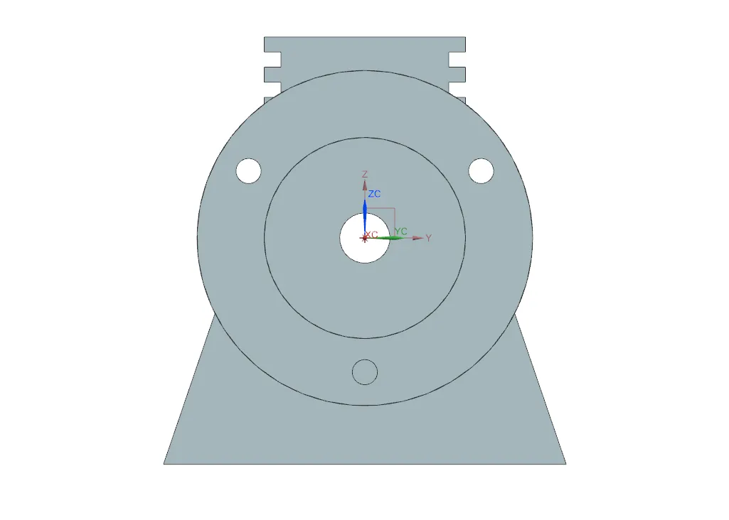
4} BLOWER :-
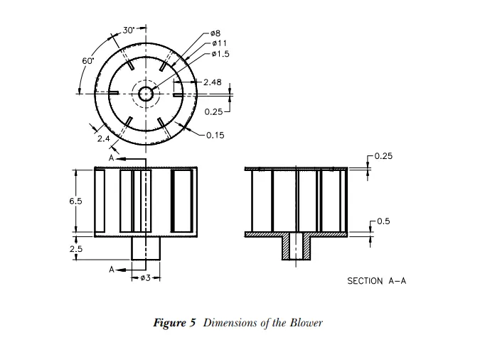
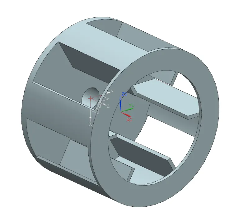
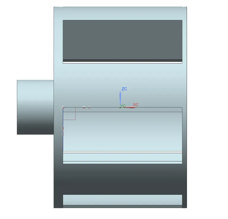
5} SHAFT :-
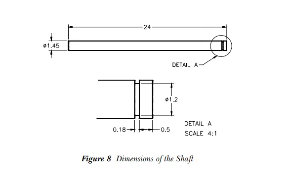
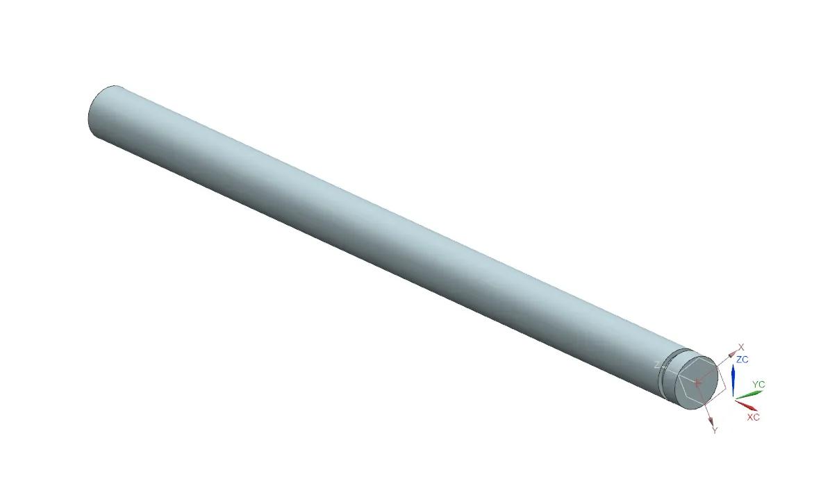
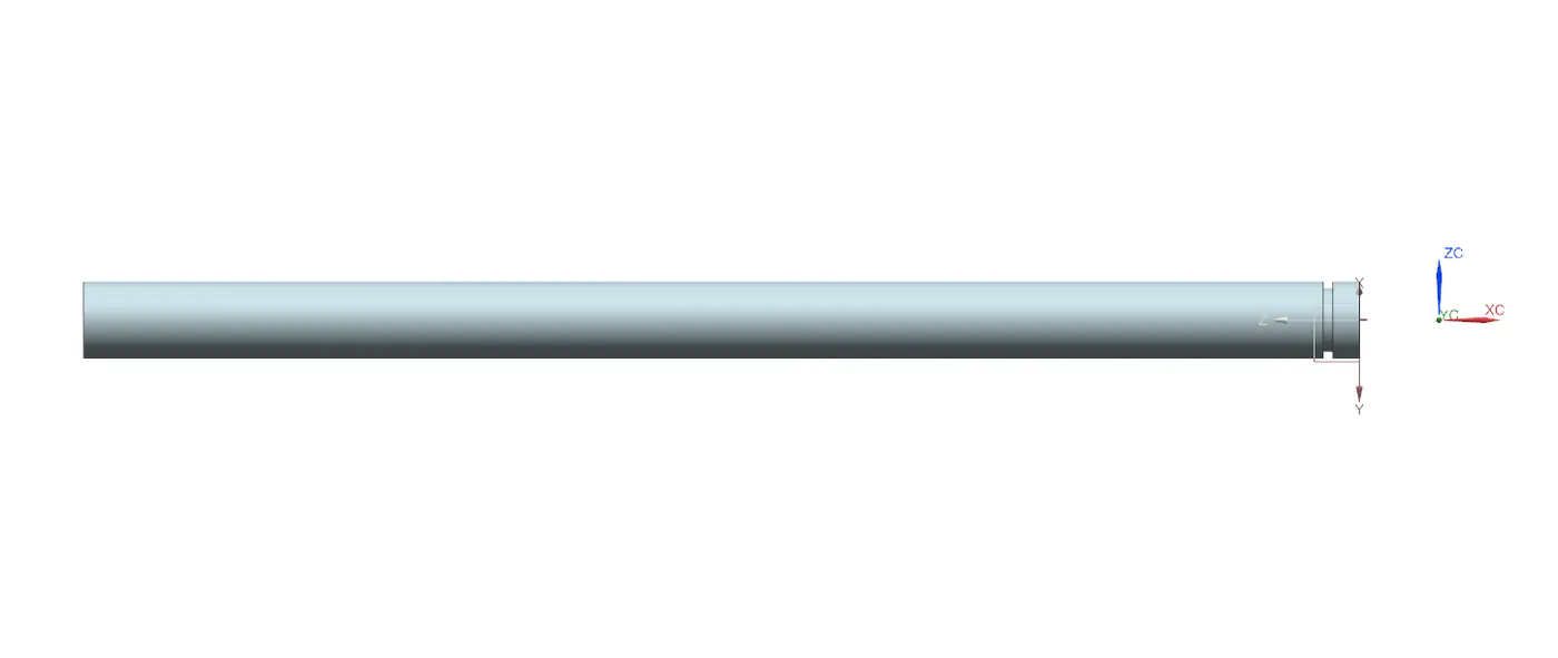
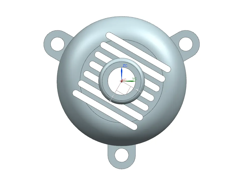
6} MOTOR COVER :-
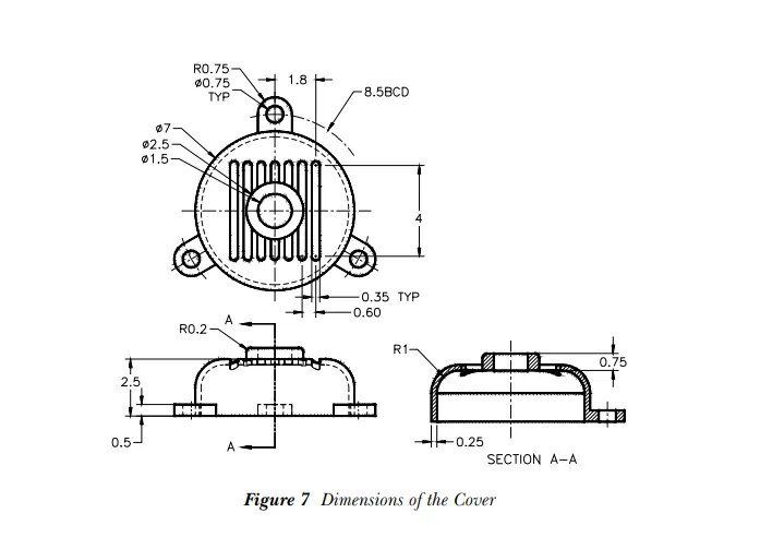
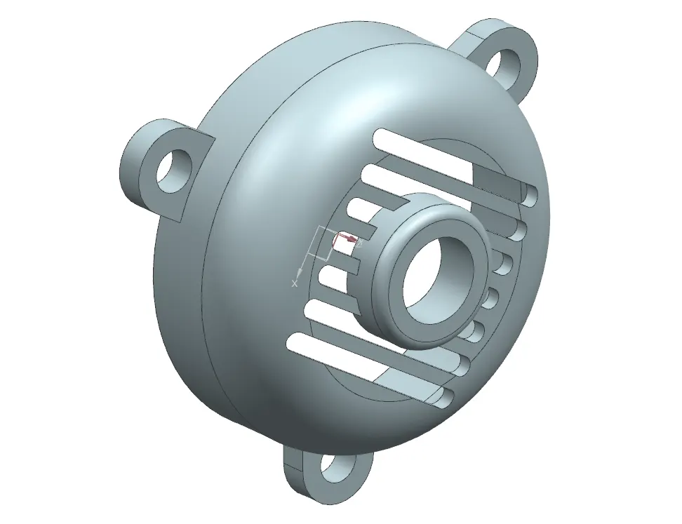
7} ASSEMBLY :-
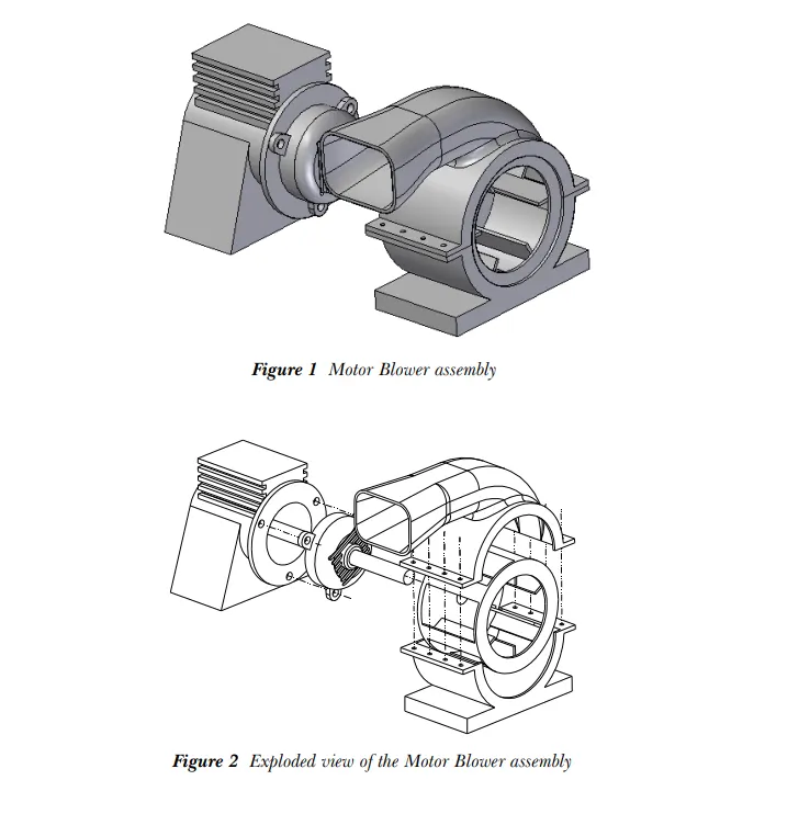
After creating all the different part files they are assembled in an assembly file by using different constraints.
assembly Constraints define relations between components in the assembly.
You can activate the “Assembly Constraints“ command by:
– Select the “Assembly Constraints“ command from “Menu=>Assemblies=>Component Position=> Assembly Constraints”
– Click on the “Assembly Constraints“ command on Home Ribbon Bar.
– Click on the “Assembly Constraints“ command on the Assemblies Ribbon Bar.
You can freely move or rotate objects on the screen when the “Assembly Constraints” command is activated due to its constraints.
- To move the component: activate the “Assembly Constraints“ command then press and hold the left mouse button on the component then drag the mouse on the screen
- To rotate the component: activate the “Assembly Constraints“ command then press and hold “alt” on the keyboard, then press and hold the left mouse button on the component and drag the mouse on the screen
Assembly Constraints pop up window :-
1} Constraint type: You can select constraint types. Also, you can deactivate constraints from the “Enabled constraint” tabs in settings.
1) Touch Align: planar or straight surfaces/edges/planes/centerlines touch or align.
2) Concentric: constraints components through circular edges.
3) Distance: specifies the distance between components' surfaces or edges.
4) Fix: fixes component on its current position
5) Parallel: defines parallel surfaces/edges/planes etc… between components.
6) Perpendicular: defines perpendicularity between surfaces/edges/planes etc… between components.
7) Align/Lock: Same as concentric but components can’t rotate around defined constraints.
8) Fit: constrains cylindrical surfaces that have the same radius.
9) Bond: defines the bond between selected components. Bonded components move together in assembly.
10) Center: centers components through selected objects. (Surfaces, planes, axis, edges, etc…)
11) Angle: defines the angle between components surfaces, edges, etc…
2} Geometry to constrain: It is used to define constraint objects. It will be active after the command started. Options changes due to the selected constraint type.
You can change the direction of the constraint by clicking the icon near the reverse last constraint.