Project
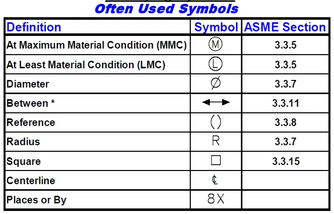
Geometric dimensioning and tolerancing (GD&T) is a system of symbols used on engineering drawings to communicate information from the designer to the manufacturer through engineering drawings.
GD&T tells the manufacturer the degree of accuracy and precision needed for each controlled feature of the part. GD&T is used to define the nominal geometry of parts and assemblies and to define the allowable variation of features.
Feature Control Frames
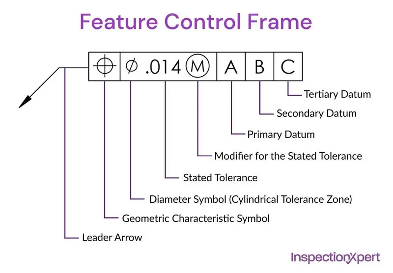
In GD&T (Geometric dimensioning and tolerancing), a feature control frame is required to describe the conditions and tolerances of a geometric control on a part's feature. The feature control frame includes four parts:
- GD&T symbol/control symbol
- Tolerance zone type and dimensions
- Tolerance zone modifiers - such as features of size
- Datum references (if required by the GD&T Symbol)
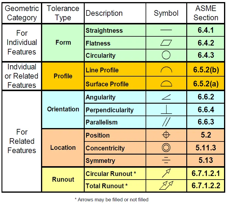
Geometric Category refers to whether or not the Feature Control Frame includes a Datum Reference Frame (DRF.) Tolerances for individual features do not have DRF’s. Tolerances for related features control one or more features relative to the specified DRF.