Project 3: Roof Modeling
ROOF MODELING ASSEMPLY
AIM:
The main aim of this project is to develop the car roof design and reinforcement from the given roof styling surface. After the design is done by a heat load and snow load calculations and check for draft analysis will be done the 0Y section of the roof.
INTRODUCTION:
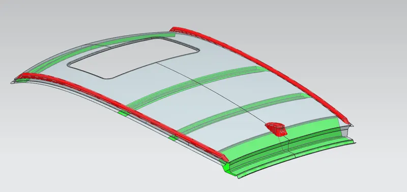
An automobile roof or car top is the portion of an automobile that sits above the passenger compartment, protecting the vehicle occupants from sun, wind, rain, and other external elements. More than strength added to for using the frond roof ,rear roof, bow roof and center roof of reinforcements. The car roof is protects passengers or goods from the weather, increase strengthening by using the front oof, rear roof, bow roof and center roof of reinforcements.
TYPES OF ROOF:
In later years, many variations on the automobile roof developed. These include:
• Convertible roofs
• Hardtops
• Sunroofs
• T-tops
METHODOLOGY:
We have created to roof is number of support rails for enough strength to with stand the load. All rails edge are fixed to a spotwelded of flatsufaces and front, bow, rear center rails are fixed to roof using mastic sealants so don't gap between the roof area and rails areas.
Designing the front, rear, bow, center rood rails are as well as according to the given master section. After compleating design need to calculate the parameter required for heat distortion in the roof are within range or not.Also we have to do check the snow load condition of strength of the roof area.
DESING CONSIDERATION OF ROOF:
- Haet distortion and snow load criteria
- Curvature study
- Draft analysis
COMPONENTS OF ROOF ASSEMPLY:
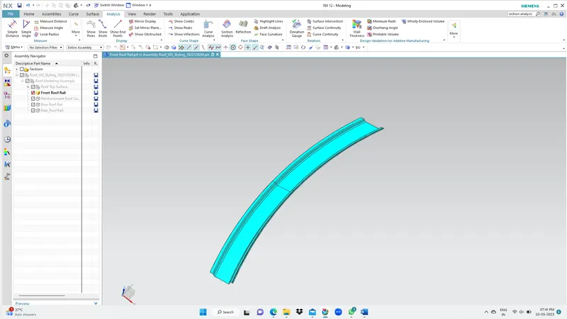
1. FRONT ROOF RAIL
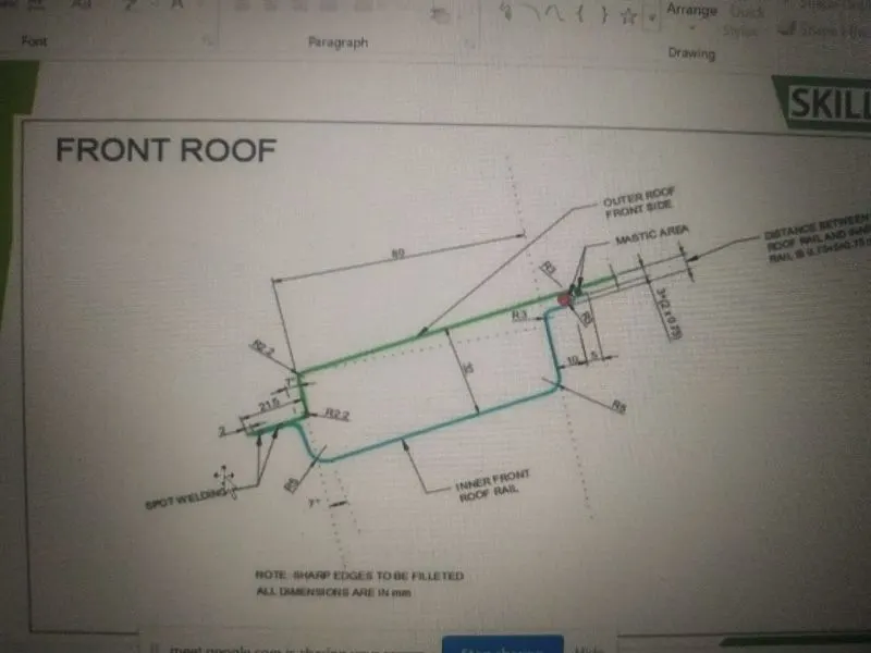
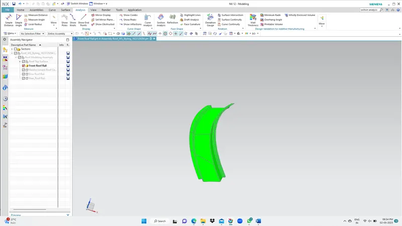
This is the reinforcement provide at front. This part is joined to biw body and windshield. Adraft angle provided for refert to the master section 7 degree . It is fixed to the BIW with spot welds and roof surface is attached with the help if mastic sealants.
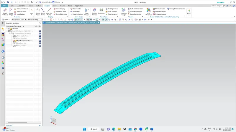
2. REINFORCEMENT ROOF CENTER
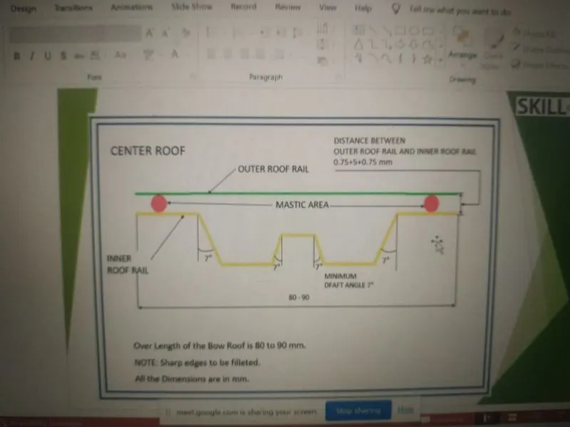
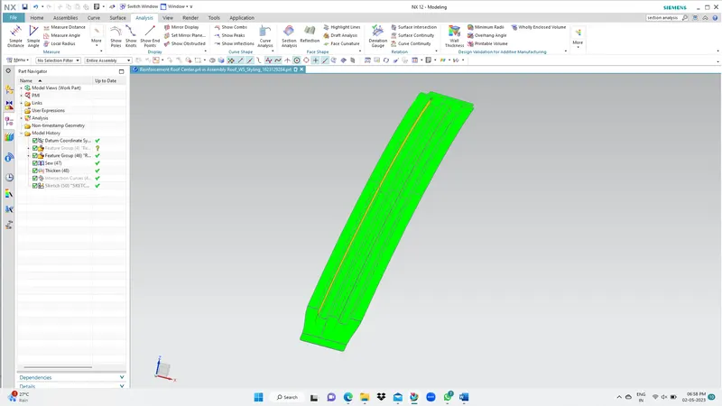
Center rail roof can be considered as reinforcement joining the right and left part of the roof. It is fixed to roof body with mastic sealants and spot weld.
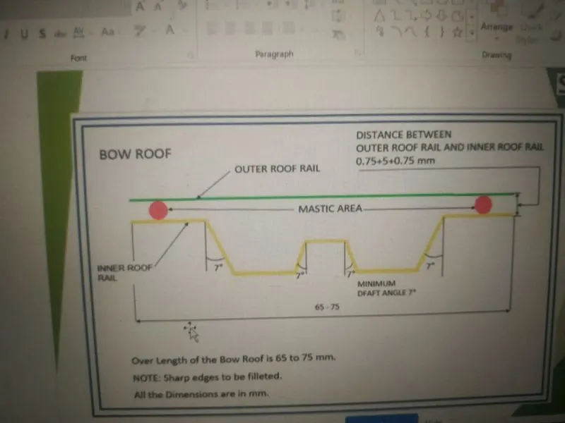
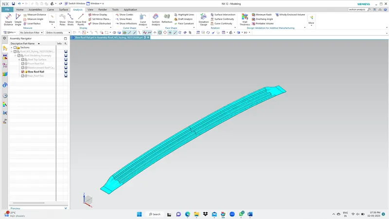
3. BOW ROOF RAIL
It is an additional reinforcement provide to increase the strength of the roof. It is fixed to roof body with mastic sealants and spot weld.
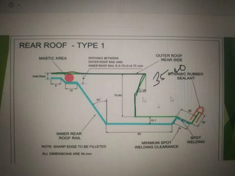
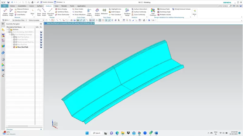
4. REAR ROOF RAIL
This is the reinforcement provide at rear side of the roof. Back door is attached with this part. It is fixed to roof body with mastic sealants and spot weld.
CURVATURE STUDY ON THE ROOF:
1. Heat Distorsion:-
W = [1.73 x 10^(-3) x L] + [1.85 x 10^(-8) x (R^2)/t] + [ 1.10x10^(-3) x l] - 2.68
Judgement Condition : OK<2>
Where
L = Roof Length in X-Direction[mm](Roof dimension in 0-Y)
R = Roof curvature
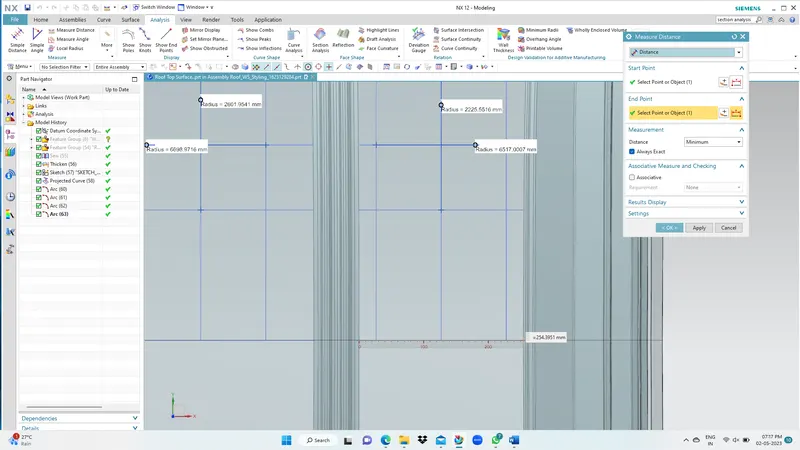
R = 2(Rx*Ry)/(Rx+Ry)
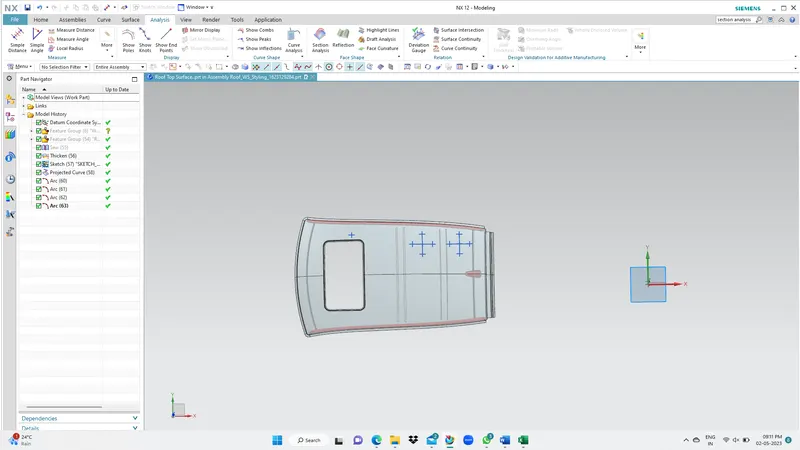
Rx = X curvature
Ry = Y curvature
t = Roof plate thickness [mm]
l = Bow Roof Span [mm]
Rx-Ry Curve:
R - Value:
ResultTable:
| W = [1.73 x 10^(-3) x L] + [1.85 x 10^(-8) x (R^2)/t] + [ 1.10x10^(-3) x l] - 2.68 | |||||||||||
| ROOF RAILS | Rx (mm) | Ry (mm) | 2(Rx*Ry) (mm) | Rx+Ry (mm) | R (mm) | t (mm) | L (mm) | R^2/t (mm) | l (mm) | W | RESULT |
| CRR-BRR | 6698.98 | 2601.95 | 34860822.02 | 3900 | 3748.1 | 0.75 | 1875.4 | 18731004.8 | 347.5 | 1.29 | PASS |
| BRR-RRR | 6517 | 2225.55 | 29007818.7 | 8742.55 | 3318 | 0.75 | 1875.4 | 14678832 | 252.3 | 1.113 | PASS |
This show the design is safe in heat distortion criteria.
2. Snow load Prediction formula:
Qr = [Iy x t2] / [α x s x [(Rx + Ry)/2]2 x 10-8]
Note: The Qr value given over here is correct. There was a typo error in the formula given in the video.
Where
α = My x Lx2 x 10-12 , My = Y(Ly-Y)
Judgement condition = Qr ≥ 3.1
250 ≤ s ≤ 380
t = Roof plate thickness [mm]
Ly = Distance between the front and rear roof Rails on the Vehicle along with 0Y[mm]
Length of Roof panel with the center point between Roof rail Front /Rear as the reference point of the front and the rear.
Lx = Distance between the Left and Right end of the roof on the Roof BOW [mm]
Width of the roof panel exposed on the surface.
Y = Distance front Front Roof Rail to Roof BOW[mm]
s = Distance for which Roof BOW bears divided load [mm]
s = L1/2 + L2/2
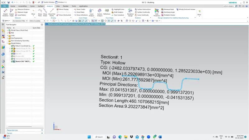
Iy = Geometrical moment of inertia of Roof BOW (Y cross-section )[mm4]
Rx = Lateral direction curvature radius of roof panel Y cross-section on Roof BOW [mm]
Roof panel curvature Radius of the Length Lx in Front view
Ry = Longitudinal Direction curvature radius of the Roof panel X cross-section on Roof BOW [mm]
Roof panel X curvature radius of length s in Side view
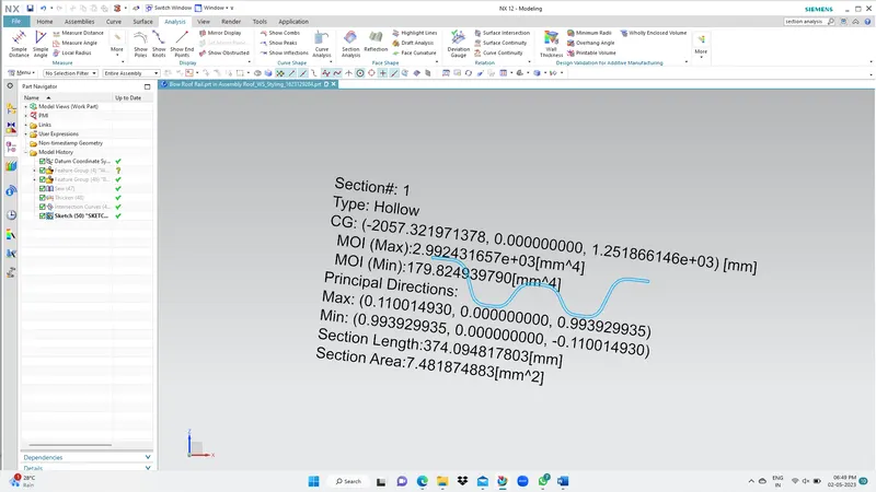
SECTION ANALYSIS:
- CENTER ROOF
2. BOW ROOF
Result Table:
| Qr = [Iy x t2] / [α x s x [(Rx + Ry)/2]2 x 10-8] | ||||||||||||
| ROOF RAILS | Iy (mm^4) | Lx (mm) | Ly (mm) | Y (mm) | L1 (mm) | L1/2 (mm) | L2 (mm) | L2/2 (mm) | Rx (mm) | Ry (mm) | Rx+Ry/2 (mm) | t (mm) |
| CRR -BRR | 179.82 | 1013.6 | 1796.9 | 989.9 | 425.2 | 212.6 | 381.8 | 190.9 | 6563.9091 | 5642.8111 | 6103.36 | 0.75 |
| My | Alpha | S (mm) | Qr | Result |
| 798768.6 | 0.820642846 | 403.5 | 0.82 | Fail |
This shows that at the second section design does not fullfil snow load criteria. Hence, to increase the strength of the roof embosses are provide on the roof surface.
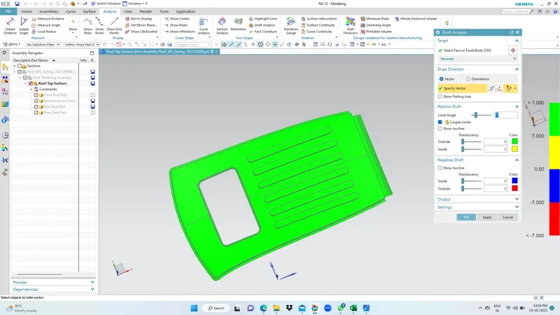
DRAFT ANALYSIS:
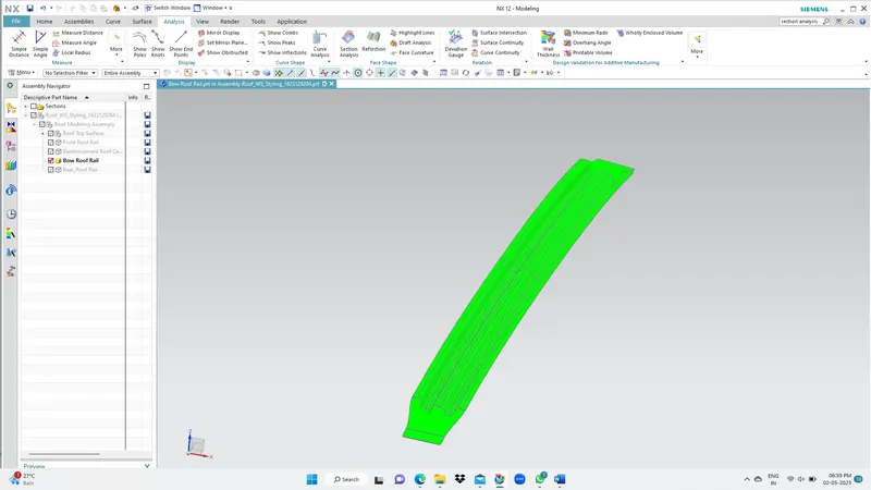
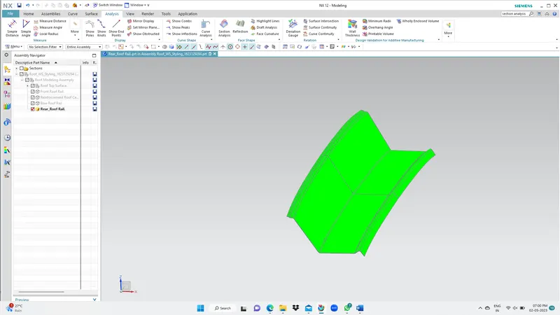
The draft analysis of all parts was done to check for proper draft angle 7 degree.
- FRONT ROOF RAIL
- CENTER ROOF
3. BOW ROOF
4. REAR ROOF
JOINING PROCESS:
Mastics are introduced between the roof outer panel and the front, center, bow rear roof rails for joining. Spot welding is also join the edge of the outer panel to front, center, bow, rear roof edgess for joining.
CONCLUSION:
Design of roof was done and check for heat distortion and snow load criteria. The model is satisfy the heat distortion criteria but not satisfy snow load criteria. So its overcome this embosses are provided on the surface.