Project 3
PROJECT-03
A- EXISTING TERRAIN :
Open "OPEN ROAD DESIGNER" software > WorkSpace : Training and Examples > WorkSet : Training-Metric > Click on new file > Save in "COMPLETED ASSIGNMENT" > Seed : Seed 3D-Metric Training.dgn > File name : EXISTING TERRAIN > Save.
Click Utilities tab > Co-ordinate System > Library > Search : UTM84-43N > Select the Co-ordinate > Ok > Co-ordinate set.
Click on Terrain tab > Additional Methods > Create Terrain Model from ASCII file > Select the csv file to import > Create Terrain Model from ASCII file tool open > Click on Create New Text Import Settings file > File Format open > Hit next > Set the Feature Type to SPOT > Set the Feature Symbology to Survey\Topo\Elevation point local > Set the column header > Hit next > Filter open > Hit next > Select the Geographical Co-ordinate System > Hit the finish > Save the Triangulation Option > Import > Date Imported.
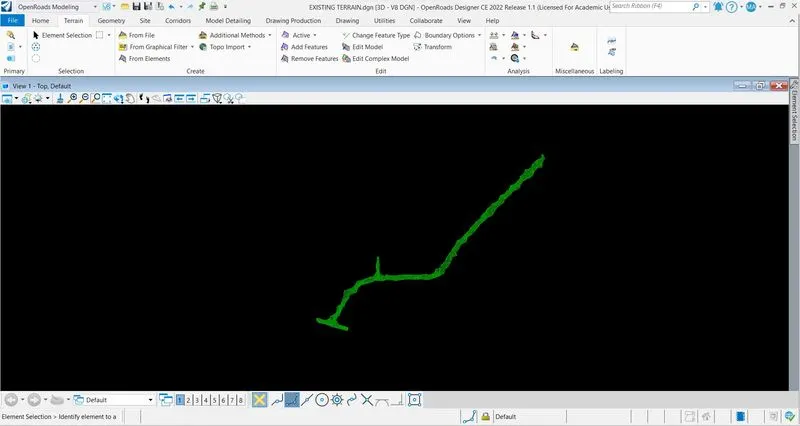
Open the Aerial Map.
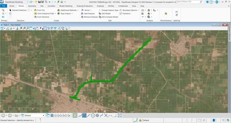
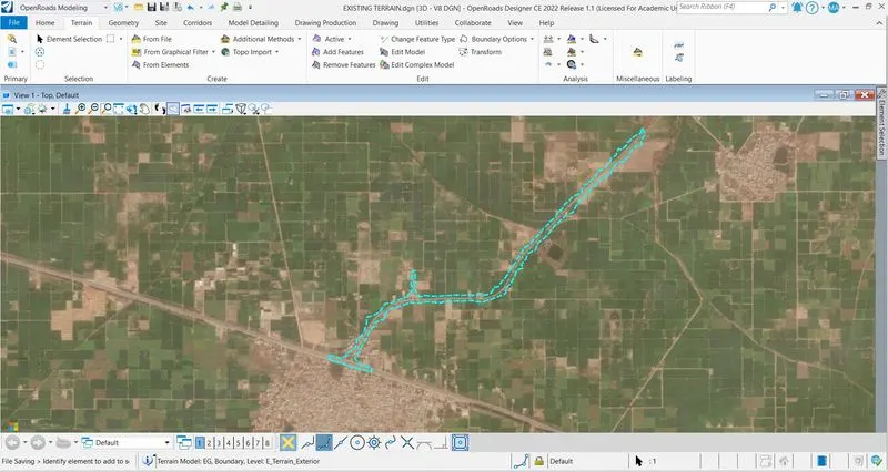
Change the Feature Defination from Existing Triangle to Existing Boundry.
B- ALIGNMENT & PROFILE :
Create a file named as ALIGNMENT with 2D Seed > Set the Co-ordinate to UTM84-43N > Reference "EXISTING TERRAIN" file, "Survey Alignment" file > Varify the map.
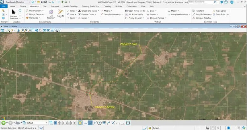
Click on Geometry tab > Click on Lines > Set the line (St.Line), where it requires > Click on Arc > Arc between elements > Spiral Arc Spiral > Locate 1st and 2nd element > Give the radius and transition length as per IRC > Hit left click > Trim both > Arc is installed > Repeat the process for reamining arc.
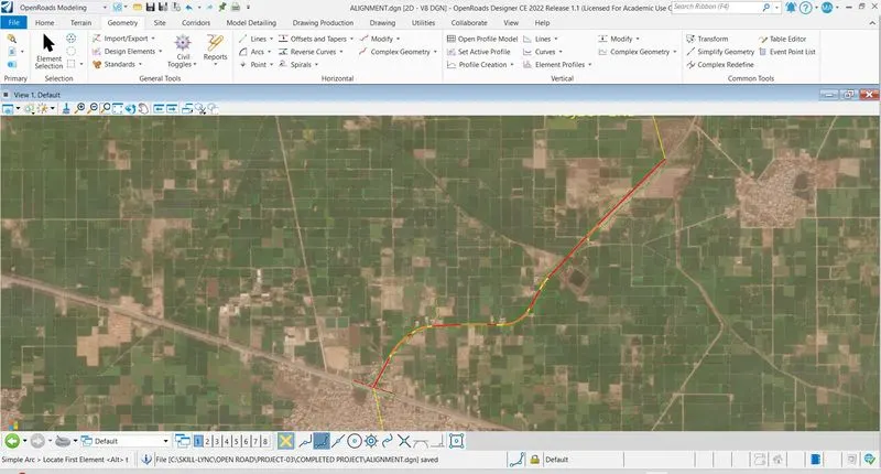
We have used 6 curves in which 4 are Spiral and 2 are Simple Curve.
1- Spiral Arc Radius = 350m
Back and Ahead Transition = 25m
2- Spiral Arc Radius = 194m
Back and Ahead Transition = 30m
3- Simple Arc Radius = 1500m
4- Spiral Arc Radius = 197m
Back and Ahead Transition = 40m
5- Spiral Arc Radius = 220m
Back and Ahead Transition = 35m
6- Simple Arc Radius = 2000m
Click on Complex Geometry > Complex By Element > Click on First Element > Make it Automatic > Select the Complex.
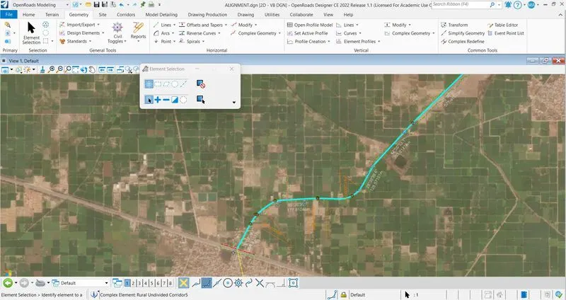
Click on line > Create the centreline for Intersecting Street and NH.
Click on Drawing Production tab > Element Annotation > Annotate Element > Right Click > Annotation install.
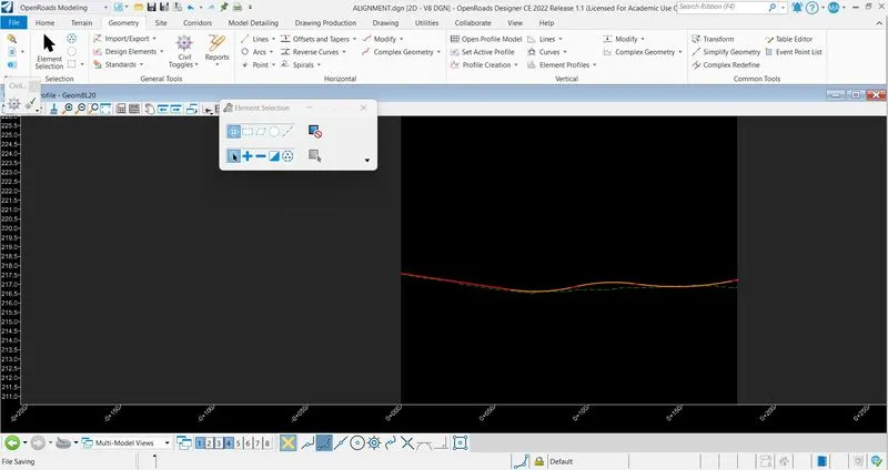
Set the terrain active > Click on NH line > Hover on it > Open Profile Model > Select the view tab > Existing Ground of NH open > By Vertical Geometry, set the layout plan for NH > Make it Complex > Set it as active.
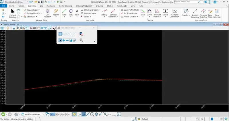
Click on Mainline > Hover on it > Open Profile Model > Select the view tab > Existing Ground of Mainline open.
Click on Profile Creation > Profile from Surface > Locate Element > Hit right click > Locate reference surface > Hit right click > Set the Feature Defination > Offset Profile is created.
Click on Profile Creation > Profile Intersection Point > Locate Element > Locate Element which Intersects > Tie point is installed.
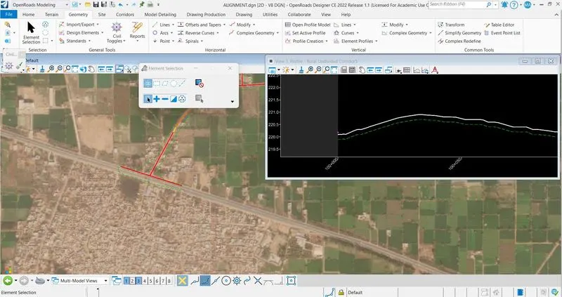
By Vertical Geometry, Create the Layout plan, make it complex and turn as active.
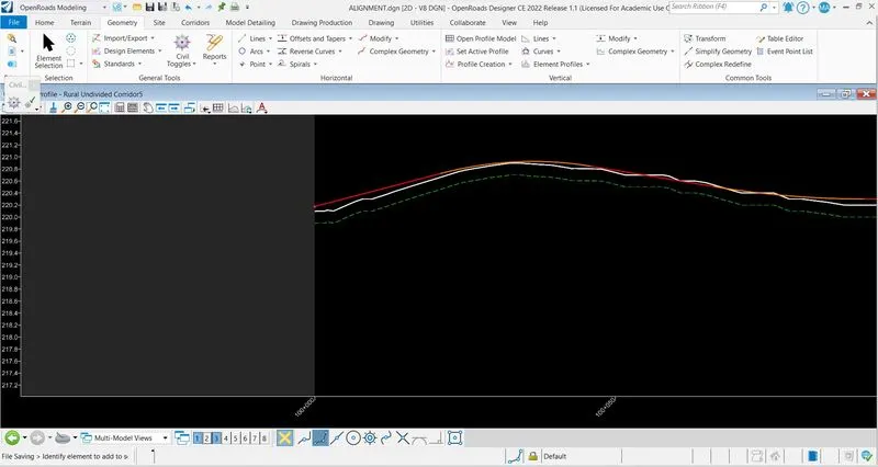
Click on Intersecting Street > Hover on it > Open Profile Model > Open in another view tab > Existing ground of Intersecting Street open.
Click on Profile Creation > Point Intersection Point > Locate Element > Locate Element which Intersects > Tie point is install.
By Vertical Geometry, Create the layout plan, make it complex and turn as active.
C- ROAD LAYOUT :
Create a new file named as "ROAD LAYOUT" with 2D seed > Set the Co-ordinate System > Reference the Alignment file.
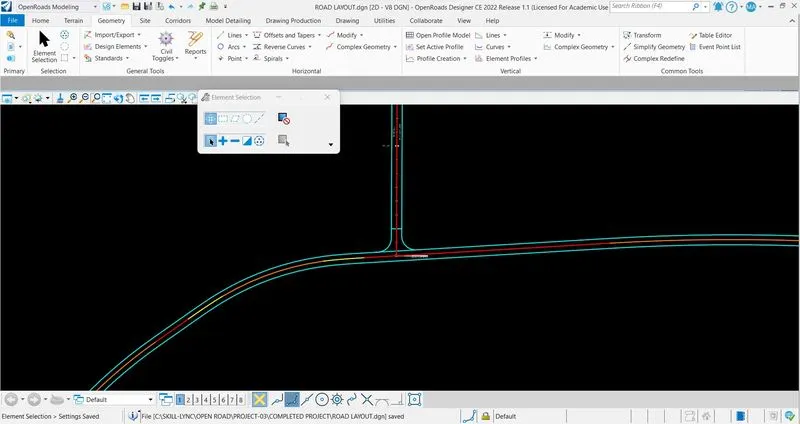
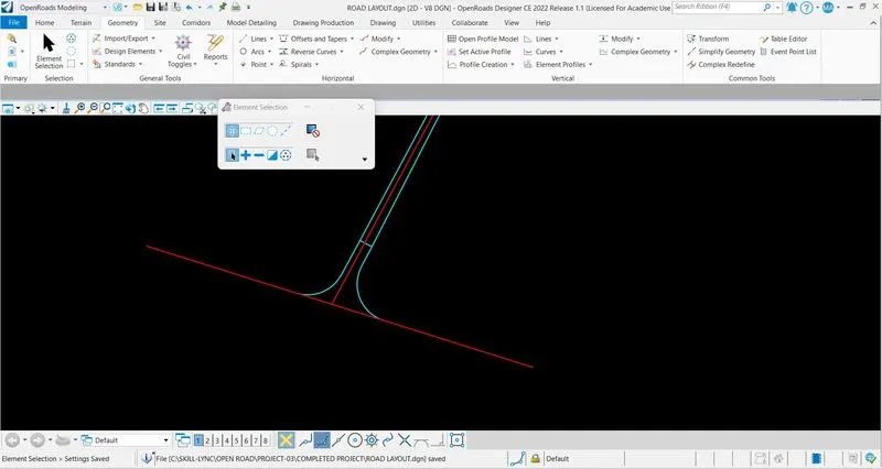
Click on Geometry tab > Offset and Tapers > Single offset partial > Start station : 100+00 > End Station : 100+100 > Set all the parameters > Variable Offset Tapers > Start Station : 100+100 > End Station : 100+140 > Set all the parameters > Start offset 5.50m > End offset : 3.5m > Single offset partial > Start Station : 100+140 > End station : 102+450.098 > Set the parameters > Offset created for one side > Repeat the process for second side > Set the offset for Intersecting Street > By Single offset partial > Set the offsety > Add fillet curve and trim.
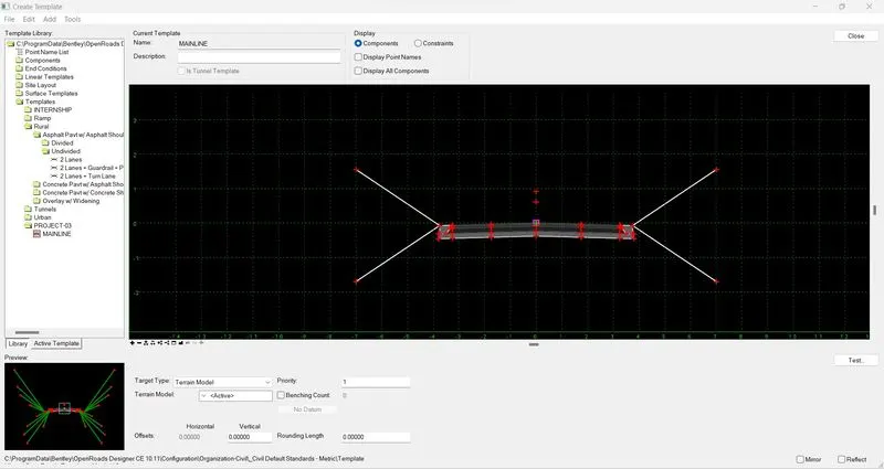
Click on Corridor tab > Template > Create Template > Make a folder > Copy the template 2 lanes, undivided, asphalt pavt w/ asphalt shoulder, rural > Draw the template as follows:
2-LANE :
Lane Width = 1.75m
Shoulder Width = 1.5m
Shoulder Slope = -2%
EC Hinge Length = 0.5m
CUT END CONDITION :
Name = Cut 2:1_LT and Cut 2:1_RT
Feature Defination = Grading\TC_CutSlope
Slope = -50%
Length = 3.25m
FILL END CONDITION :
Name = Fill 2:1_LT and Fill 2:1_RT
Feature Defination = Grading\TC_FillSlope
Slope = -50%
Length = 3.25m
D- SUPERELEVATION :
Create a new file named as "SUPERELEVATION" with 2D seed > Set the geographic co-ordinate system > Reference the Alignment file > Verify the location.
Click on Corridor tab > Superelevation > Create Superelevation Sections > Set the parameters > Name : SECTION > Start Station : 100+00 > End Station : 102+450.098 > Minimum Target Length : 10000 > Lane Creation Method : Template > Right click to reset > Superelevation Section is created.
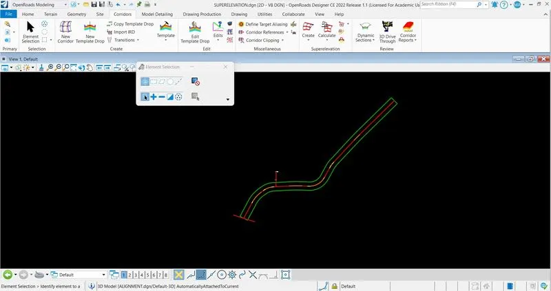
Create Superelevation Lanes by Road Template > Locate Superelevation Section > Select Template > Superelevation Lanes created.
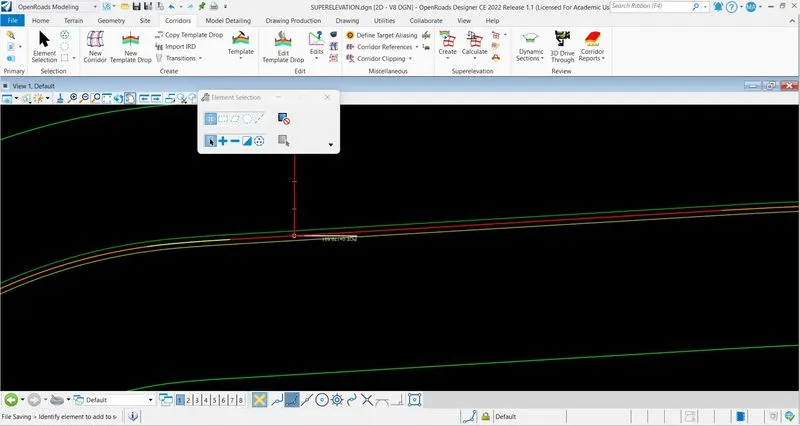
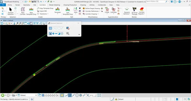
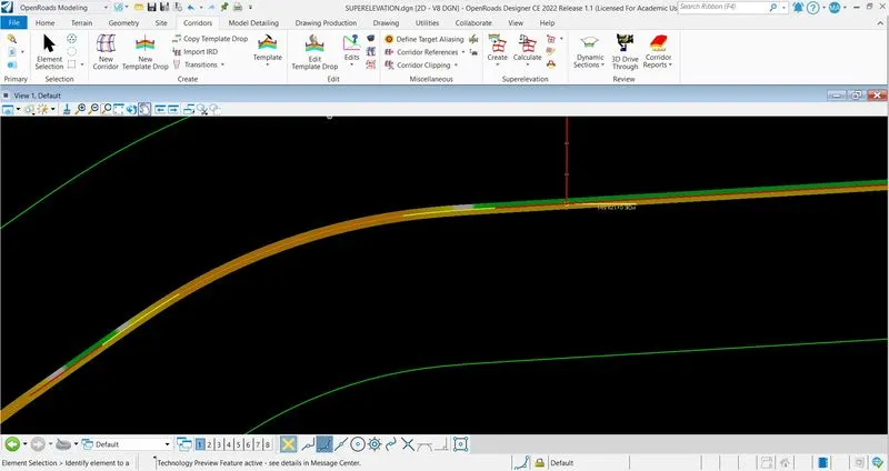
Calculate Superelevation > Set the Parameters > Rules file name : AASTHO_2018_metric.xml > e selection : 4% > L-selection : Speed Table > Design Speed : 50 > Pivot Method : Crown > Superelevation calculated.
E- CORRIDOR :
Create a new file named as "CORRIDOR" with 2D seed > Set the Geographic Co-ordinate System > Reference the Alignment file, Road Layout file and Existing Terrain file > Verify the location.
Click on Corridor tab > New Corridor > Select the Baseline > Right click > Set the Feature Defination > Edit the name > Select the end point > Corridor created for MAINLINE.
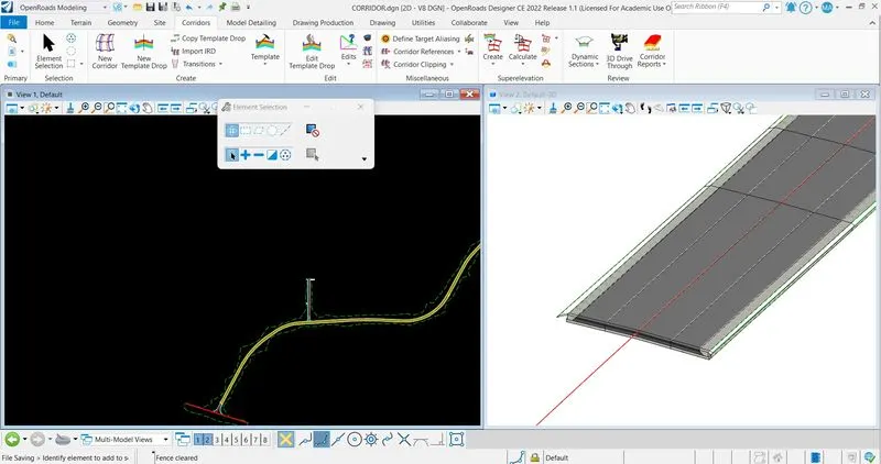
Repeat the same procedure to create the corridor for Intersecting Street.
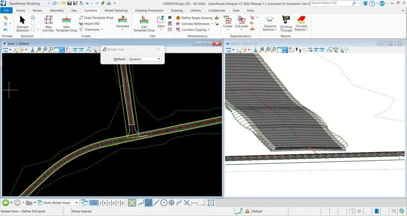
Reference the Superelevation file > Superelevation tab > Calculate > Assign to Corridor > Hit ok > Superelevation is assigned to corridor.
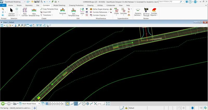
Click on Edits tab > Create Point Control > Locate the Corridor > Set the parameters > Set the start station > Set the end station > Set the Control Description > Select Point > Select Model > Select the Control Type > Select Plan Element > No use of secondary alignemnmt > Set Priority > Set the Horizontal Offsets.
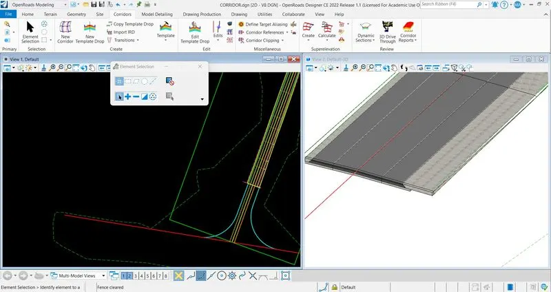
Open the ROAD LAYOUT file > RTeference Existing Terrain file > Set the terrain file active.
Click on Geometry tab > Vertical Geometry > Element Profiles > Profile by Slope from Element > Locate first element to profile > locate the remaining element and hit right click > Locate reference element hit right click > Point Selection : All > Profile adjustment : none > Vertical offset : 00 > Slope : -2% > Left click to reset > Profile is created.
Click on Element Profiles > Quick Profile Transition > Quick Transition Method : Parabola > Select the line > Profile is created.
Click the Intersecting Line > Hover on it > Open Profile mOdel > Select the new tab > Existing ground profile open > Click on Profile Creation > Point Intersection Point > Locate Element to show Intersection > Locate Element which Intersects > Intersection Point is install in profile > Create Layout plan by Vertical Geometry > Make it Complex > Set it as active profile > It is showing in Profile Layout.
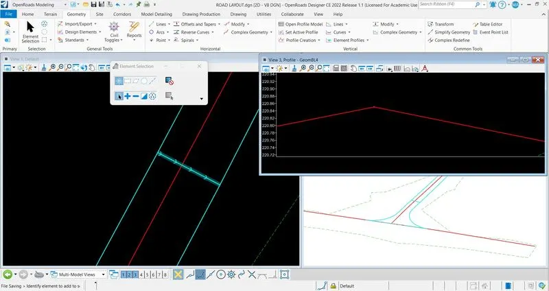
Repeat the same procedure for one more Intersection.
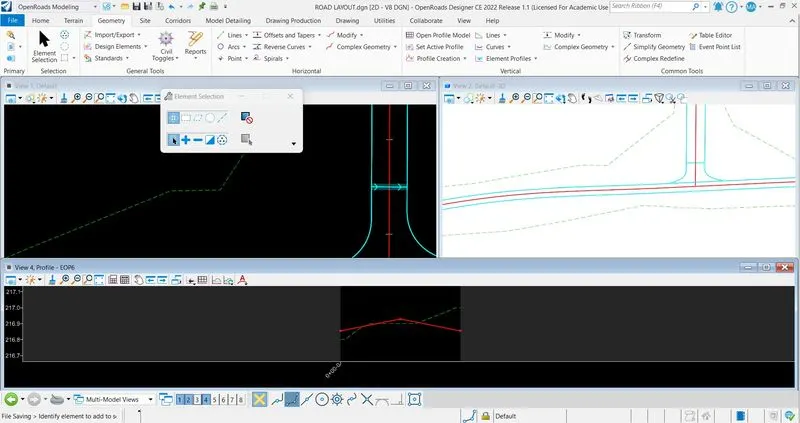
Open Corridor file > Reload the ROAD LAYOUT file > Turn on all the construction.
Click on Terrain tab > Click on From Elements > Locate all the element > Right click to reset > Feature Type : Boundry > Edge Method : Remove Slivers > Left Click > Surface is created > Repeat the same procedure for Junction-02.
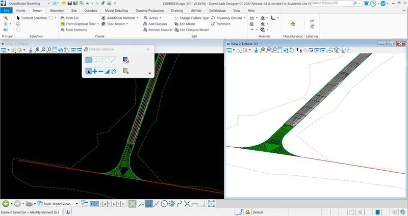
Click on Corridor tab > Template > cReate Template > EC_LT and EC_RT > Click on Model Detailing > Surface Template > Pick Template : Asphalt Pavment > Locate a terrain model > General Apply Clip Boundry : No > Set the data point to accept selection > Surface Template is created.
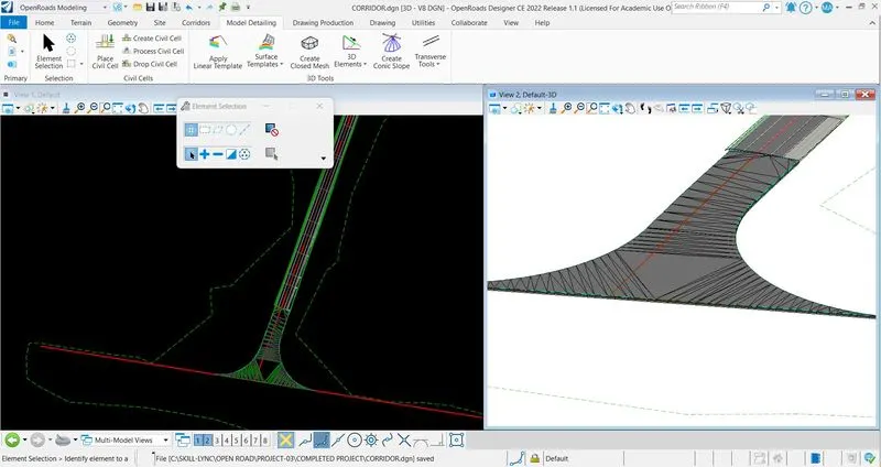
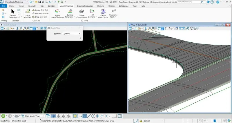
Apply Linear Template > Locate Element to apply > Template : EC_RT > Set the Start Station > Set the End Station > Exterior Corner Sweep Angle > Right Click > Linear Template is created > Repeat the same procedure for 2nd Intersection.
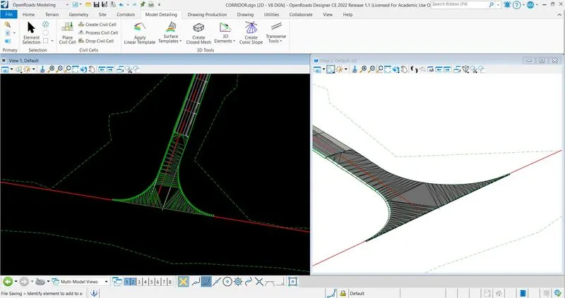
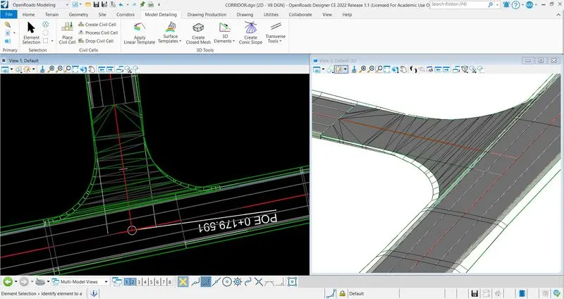
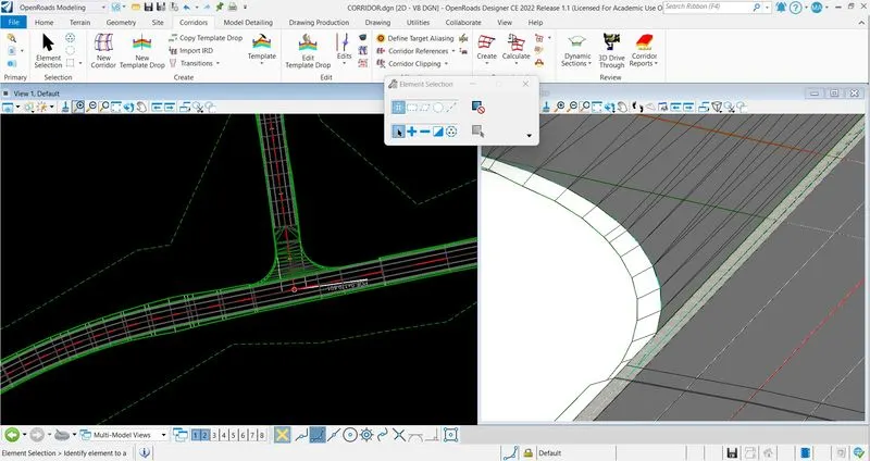
Click on Corridor tab > Corridor objects > End Condition Exception > Add new > Set the parameters > Name : NS_LT > Apply ECE To : Backbone only (left) > Select Start and Stop point > Main line Slope elemented at intersection point.
F- QUANTITY :
Create a new file named as "MATERIAL COMPUTATION" with 2D seed > Set the Geographic Co-ordinate System > Refrence Alignment file, Corridor file and Existing Terrain file > Verify the location.
Click on Home tab > Civil Analysis > Element Component Quantity > Select the element > Right click to reset > Element Component Quantities evaluated > Click on Report > Report open > Save in XL format.
Click on Civil Analysis > Create Cut Fill Volumes > Set Cut Feature Defination > Set Fill Feature Defination > Compute Unsuitable : No > Compute Custom : No > Compute Substrata : No > Data point to accept Selection > Left click > Cut and fill area are developed.
Click on Drawing Production tab > Named Boundry > Place Name Boundry > Civil Cross-section > Select the Alignment > Set the strat location > Set the end Location > Set the interval > Set the left and right offset > Cross section is created.
Go to Home tab > Civil Analysis > End area volume report > Named Boundrt grouped > Right click to reset > End area volume report is created > Save it in XL file.
Open Alignment file > Press Right click > View Control > Plan/Profile views > Click on Reports > Horizontal Geometry Report > Locate first element > Right click to reset > Set the start and end station > Interval : 00+00 > Include event point : none > Include profile : none > Right click to reset > Repeat the process for Intersection Street.
Click on Reports > Profile Report > Locate first profile element > Right click to reset > Repeat the same procedure for Intersecting Street.
Open Superelevation file > Superelevation > Superelevation Report > Locate first superelevation section > Right Click to reset > Superelevation Report is generated.
Open Corridor file > Click on Home tab > Report > Station Offset Report > Locate Element > Locate first offset element > Locate next offset element > Right click to reset > Station Offset report is generated.
G- SHEET :
Create a new file named as PLAN AND PROFILE with 2D seed > Set the Co-ordinate System > Refrence the Existing Terrain, Alignment and Corridor.
Click on Drawing Production tab > Named Boundry > Placed Named Boundry > Civil Plan > Drawing Seed : A1_PLAN PROFILE_PLAN > Select the Alignment > Set the start point > Set the end point > Frame is created.
Open Plan and Profile view > Named Boundry > Placed Named Boundry > Click on Civil Profile > Drawing seed : A1_Plan-Profile_PROFILE > Method : From Plan Group > Plan Group : Rural Undivided Corridor 6 > Left click to accept.
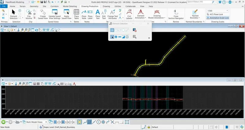
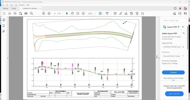
Expand Named Boundry > Expand Plan Group > Right click on Rural Undivided Corridor-06 > Create Plan/Profile drawing > Set the location > Hit ok > Plan and Profile Sheet is created.
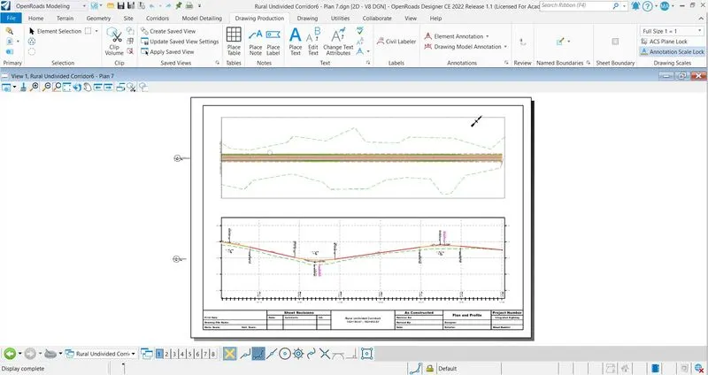
Create a new file named as "CROSS-SECTION SHEET" with 2D seed > Set the Co-ordinate System > Refrence Alignment, Existing Terrain and Corridor.
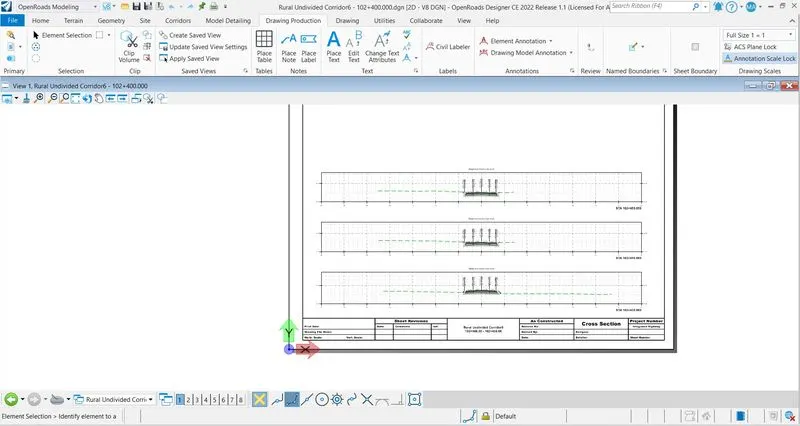
Click on Drawing Production tab > Named Boundry > Placed Named Boundry > Civil Cross-Section > Drawing seed : A1_XS > Select the Alignment > Set the Start location > Set the end location > Left click to set.
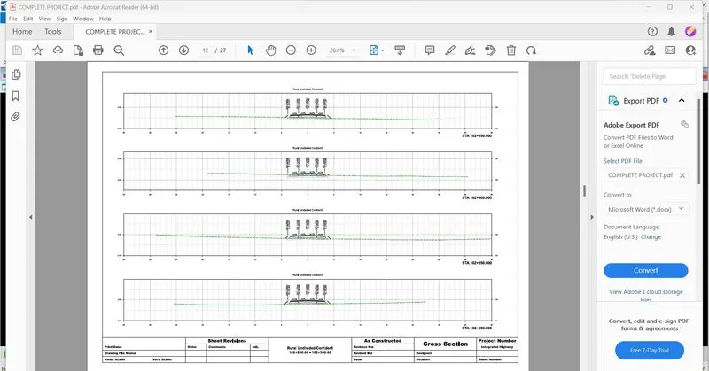
Expand Named Boundry > Expand Cross-Section group > Right click on Rural Undivided Corridor-6 > Create Cross-Section drawing sheet > Set the path > Hit ok > Cross section sheet is created.
H- PRINT :
Click on File > Print > Print Organizer > Set the option > Print.