System-Level Simulation of a BAJA ATV in Simulink
OBJECTIVE:
- To carry out system-level simulation of a simple model of a BAJA All-Terrain Vehicle on Simulink.
- To prepare a Technical Report explaining the model properties of the BAJA ATV based on the following conditions:
- CTV Ratio Input is fed to the system using a Signal Builder Block
- CTV Ratio Input is fed to the system using a Lookup Table.
RELATED THEORY:
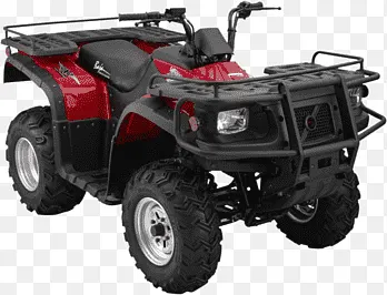
- All-Terrain Vehicle (A.T.V.): All-Terrain Vehicles are motor driven, single seater vehicles which, as the name suggests can be comfortably used in all kinds of terrains, thus making it apt for off-road vehicular conditions as well. The steering of the vehicle is generally controlled using handlebars and the tyres fitted in this vehicle are generally low-pressure tyres or non-pneumatic tyres. Due to their excellent off road capabilities, compact size and manoeuvrability, the vehicle finds use in various sectors of the industry like agriculture, sports, small- scale forestry, defence, etc.
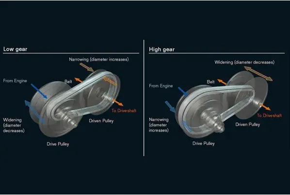
- Continuously Variable Transmission (C.V.T.): A Continuously Variable Transmission (C.V.T.) is a type of a single-speed automatic gearbox. In a C.V.T. equipped vehicle, there is no clutch pedal.
A CVT gearbox has a relatively simple arrangement of two cone-shaped pulleys with a V-shaped drive belt connecting them. One pulley is attached to the engine, while the other is joined to the wheels. When you press the accelerator, the engine revs and the cone moves according to the amount of power asked for. The other cone adjusts accordingly so that the drive belt maintains the same tension, and this is what determines how the car accelerates.
As the two cones move independently, that means there are no set gear ratios as you would find in a conventional auto or manual, so a CVT is, in effect, a single-speed unit with infinite gear ratios available instead of multiple speed units with each having a particular gear ratio.
SOLUTIONS TO OBJECTIVES:
1.1) Solution to Objective:Carrying out System Level Simulation and preparing a Technical Report for a BAJA All-Terrain-Vehicle where C.V.T. Ratio Input is fed to the system using a user-defined Signal in a Signal Builder Block.
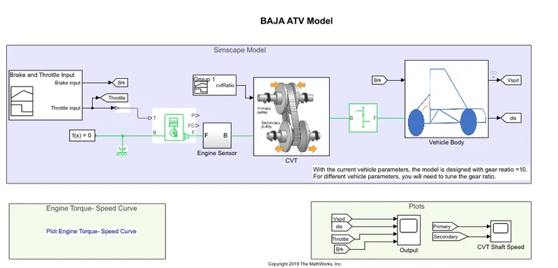
The Simulink Model for carrying out simulation of BAJA ATV using user-defined Simulink Signals via Signal Builder Blocks
The important blocks and their corresponding functionalities in the model are as follows:
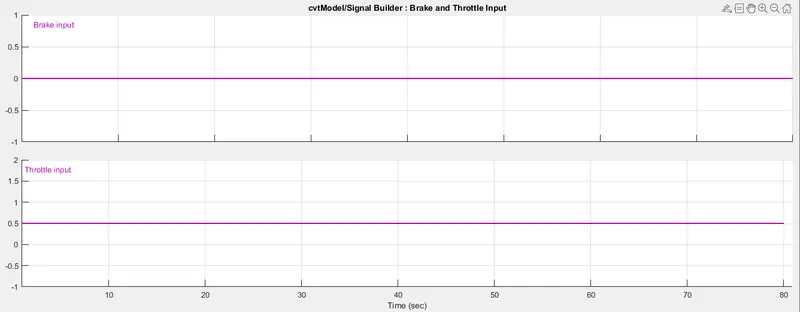
- Signal Builder Block(1): This block helps in creation and generation of interchangeable groups of signals whose waveforms are piecewise linear. Using this block, the input signals of Brake and throttle were created and generated to be fed into the system.
Signal Builder Block for creating & generating user defined Brake & Throttle input in form of Simulink Signals
- Generic Engine Block: This block represents a system-level model of a general I.C. engine(can be used to represent Diesel or S.I. engine).The throttle input signal generated from the Signal Builder block is fed to the Generic Engine Block. The throttle input signal (fed to Port T of the block) lies between zero and 1 and specifies the torque demanded from the engine as a fraction of the maximum possible torque. If the engine speed falls below the Stall speed, the engine torque is blended to zero. If the engine speed exceeds the Maximum speed, the simulation stops and issues an error message.
Connections F and B are mechanical rotational conserving ports associated with the engine crankshaft and engine block, respectively. Connections P and FC are physical signal output ports through which engine power and fuel consumption rate are reported.
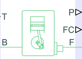
Generic Engine Block
The Speed-Torque parameterizations provided in the Block are as follows:
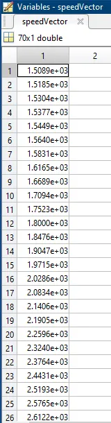
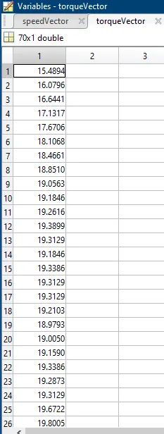
Speed Vector Data used Torque Vector Data Used
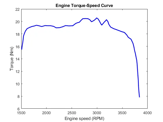
Engine Torque-Engine Speed Curve
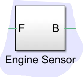
- Engine Sensor Sub-System:
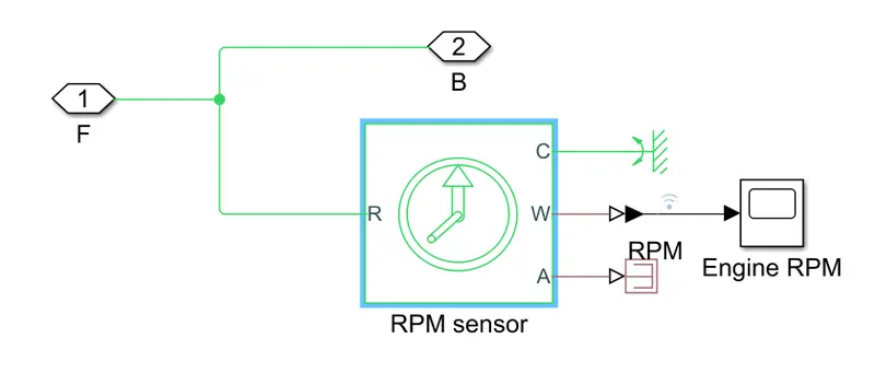
Engine Sensor Sub-System Inner View
Engine Sub-System Outer View
A seperate sub-system for measuring the angular velocity from the generic engine has been implemented to avoid complexity and overcrowding on the main Model Window. The main important block(s) in the the sub-system are as follows:
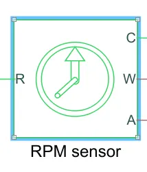
- RPM Sensor: This block represents an ideal Rotational Motion Sensor. It measures angular velocity or angle in a mechanical rotational network. The sensor is ideal since it does not account for inertia, friction, delays, energy consumption, and so on.
The physical signal ports W and A report the angular velocity and angle, respectively, of port R relative to port C. The measured angular velocity is positive when the angular velocity at port R is greater than the angular velocity at port C.
This block takes engine power signal generated from the Generic Engine Block as input and can return signals representing angular displacement and the angular velocity of the engine as output.
RPM Sensor Block
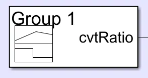
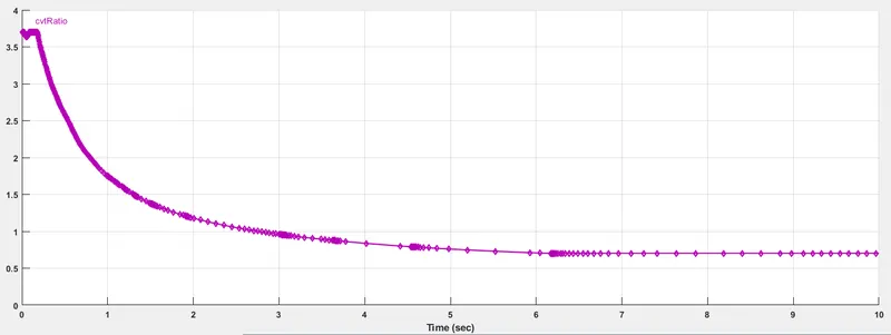
- Signal Builder Block(2): Again a Signal Builder block has been added to the model in order to create and generate Variable Gear Ratio(varies w.r.t. Time) in the form of signals. Since the signals created and generated in the Signal Builder Block are user-defined, they can be modified as per conditions by the user. The signal generated as output from this Signal Builder Block depicting Variable Gear Ratio is fed as input to the CVT Sub-System.
Signal Builder Block for feeding the CVT Gear Ratio data in form of Simulink Signal to the CVT Subsystem
- CVT Sub-System:
CVT Subsystem Inner View
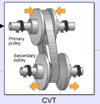
CVT Subsystem Outer View
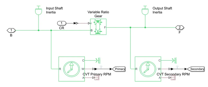
A seperate sub-system for implementing the variable gear ratio to obtain the required angular velocity of the input shaft/pulley and the output shaft/pulley to obtain the required vehicle velocity has been created to avoid complexity and overcrowding on the main Model Window.The Sub-system takes input of the Engine Power signal from Generic Engine block and the Variable Gear Ratio Signal from the ‘cvtRatio’ Signal Builder Block. The main important block(s) in the the sub-system are as follows:
- Variable Ratio Gear Block: This block represents a variable ratio gearbox such as implemented by mechanical belt CVT, electric, or hydraulic transmissions. The physical signal input r defines the ratio of input to output angular shaft velocities.
Connections B (base) and F (follower) are mechanical rotational conserving ports.
The signal emanating from the Signal Builder Block named ‘cvtRatio’ is fed to the ‘r’ port of this block . This block then implements the gear ratio it received from the ‘cvtRatio’ Signal Builder block to the the shafts connected to the B port(corresponds to Base shaft or input shaft) and F port of the block(corresponds to Follower shaft or output shaft).
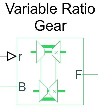
Variable Ratio Gear Block
- Inertia Block: This block represents an ideal mechanical rotational inertia.
This block has one mechanical rotational conserving ports. The difference is purely graphical, as the ports are rigidly linked.This means that the inertia torque is positive if the inertia is accelerated in the positive direction.
The angular velocity of the shafts are affected by the inertia on the shafts that occurs due to variable gear ratio implemented on the shafts. The variable gear ratio(varying w.r.t. time) causes the changes in the angular velocities of the shaft w.r.t. time which in turn leads to inertia on the shafts.

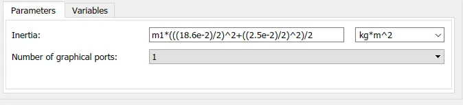
Inertia Block Inertia Parameters for Input Shaft
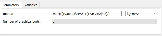
Inertia Parameters for Output Shaft
- Simple Gear Block: Represents a fixed-ratio gear or gear box. No inertia or compliance is modeled in this block. can optionally include gear meshing and viscous bearing losses.
Connections B (base) and F (follower) are mechanical rotational conserving ports.The relation between base and follower rotation directions with the Output shaft rotates parameter need to be specified. Optionally thermal effects can be included and thermal conserving port H needs to be exposed by setting Friction model to a temperature-dependent setting.
This block has been added to increase speed of the output shaft connected to the block that will ultimately be connected to the rear axle of the vehicle.
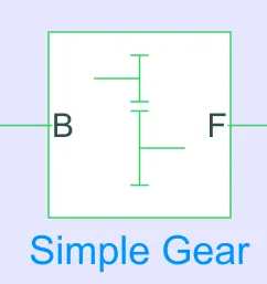
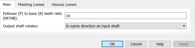
Simple Gear Block Parameters for Simple Gear Block
- Vehicle Body Sub-System:
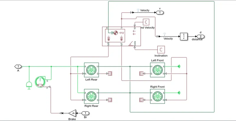
Vehicle Body Subsystem Inner View
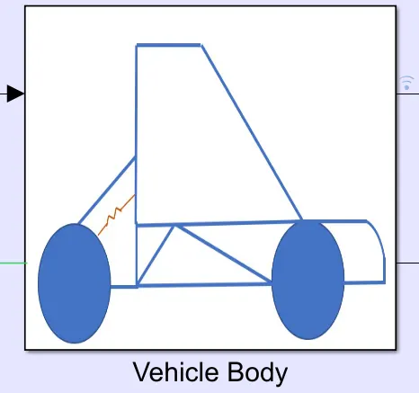
Vehicle Body Subsytem Outer View
A seperate sub-system for modelling the vehicle body, the tires, the axle system has been created.This sub-system has been created to avoid complexity and overcrowding on the main Model Window.The Sub-system takes the output signal from the Simple Gear Block(representing the angular velocity of the output shaft being connected to the Vehicle Body Sub-System) and the Brake Signal(generated from the ‘Brake and Throttle Input’ Signal Builder Block) as input and returns the distance travelled by the vehicle and the velocity of the vehicle as output. The main important block(s) in the the sub-system are as follows:
- Double-Shoe Brake Block: This block represents a brake arranged as two pivoted rigid shoes symmetrically installed inside or outside a drum and operated by one actuator. The actuator force causes the shoes to exert a friction torque on a shaft connected to the drum.
Connection S is a conserving rotational terminal associated with the drum shaft. Connection F is a physical signal port representing the force input to the actuator. Positive force creates friction torque that resists shaft rotation. Optionally thermal effects can be included and thermal conserving port H can be exposed by setting Thermal port to Model.
The Simulink Signal representing the Brake signal from the the ‘Throttle and Brake Input’ Signal Builder block is first multiplied by a value of 1000 using the Gain Block and then fed to the port F of the Double-Shoe Brake Block as a physical signal. The Double –Shoe Brake returns a signal representing the angular velocity of the drum shaft of the wheel on application of braking force via the 2 rigid shoes on the Drum Shaft. This output mechanical signal from the Double Shoe Brake block is fed to the input signal of the sub-system representing the angular velocity of the output shaft from the ‘Simple Gear Block’(created outside the sub-system).
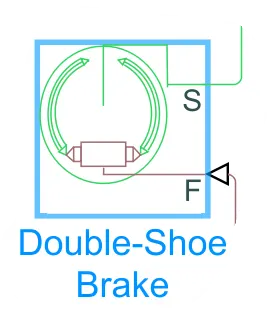
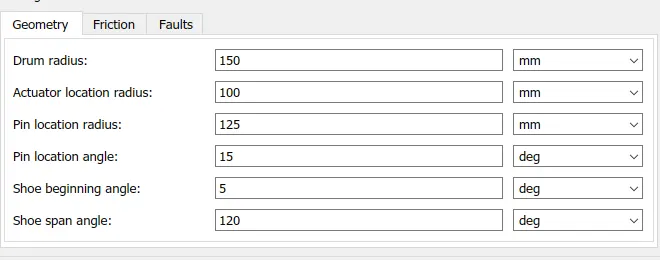
Double Shoe Brake Block Geometry Parameters for Double Shoe Brake Block
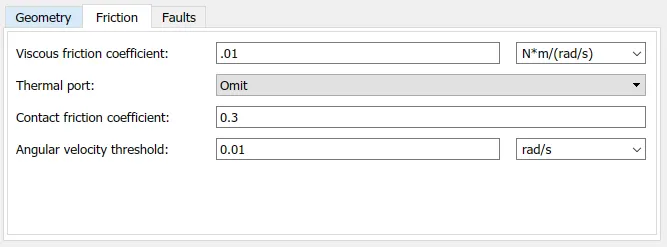
Friction Parameters for Double Shoe Block
- Inertia Block: The block represents an ideal mechanical rotational inertia.
The block has one or two mechanical rotational conserving ports. The difference is purely graphical, as the ports are rigidly linked. The block positive direction is from its port to the reference point. This means that the inertia torque is positive if the inertia is accelerated in the positive direction.
Since the signal representing angular velocity of the shaft originating from the output port of the ‘Simple Gear’ Block is changing w.r.t. time, thanks to application of the Continuously Variable Transmission to the system, the changes in angular velocity of the shaft leads to inertia force acting on the shaft.
The inertia value being applied on the mechanical signal representing the angular velocity of the shaft is 10-1 kg m2.
- Tire(Magic Formula) Block: Represents the longitudinal behavior of a highway tire characterized by the Tire Magic Formula. The block is built from Tire-Road Interaction (Magic Formula) and Simscape Foundation Library Wheel and Axle blocks. Optionally, the effects of tire inertia, stiffness, and damping can be included.
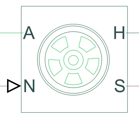
Tire(Magic Formula) Block
Connection A is the mechanical rotational conserving port for the wheel axle. Connection H is the mechanical translational conserving port for the wheel hub through which the thrust developed by the tire is applied to the vehicle. Connection N is a physical signal input port that applies the normal force acting on the tire. The force is considered positive if it acts downwards. Connection S is a physical signal output port that reports the tire slip. Optionally expose physical signal port M by setting “Parameterize by” to Physical signal Magic Formula coefficients. Physical signal port M accepts a four element vector corresponding to the B, C, D, and E Magic Formula coefficients.
Four such Blocks are added to the Sub-System. 2 of them represent the tires at the front end of the vehicle and the other two represent the tires at the rear end of the vehicle.
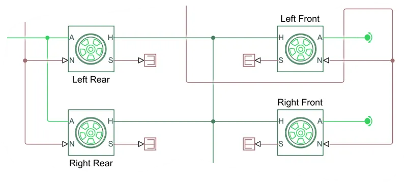
The input signal to the sub-system representing the angular velocity of the output shaft(emanating from the output port of the Simple Gear Block)is now connected to the ‘A’ ports of the two Tire(Magic Formula) Block representing the two tyres of the rear end of the vehicle. Note that this input signal to the two Tire(Magic Formula) blocks has also been connected by the output signals emanating from ‘Inertia’ block and the ‘Double-Shoe Brake’ block. The signal has only been connected to the the ‘Tire(Magic Formula)’ blocks representing the tires at the rear end of the vehicle because the rear wheels are responsible for the velocity of the vehicle.
The parameters added to the the Tire(Magic Formula) blocks representing the tyres of the rear end and front end of the vehicle are as follows:
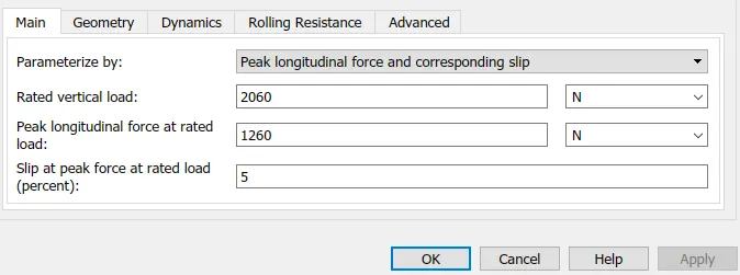
Main parameters for all 4 Tire(Magic Formula) Blocks
The other two Tire(Magic Formula) blocks that depict the the tires at the front tend of the vehicle have their A ports connected to ‘Rotational Free End’ block indicates that the tires are free to rotate as per steering.
The H ports of the four tires are connected to each other.
The port S of the blocks have no physical signifance.
- Vehicle Body Block: This block represents a two-axle vehicle body in longitudinal motion. The block accounts for body mass, aerodynamic drag, road incline, and weight distribution between axles due to acceleration and road profile. The vehicle can have the same or a different number of wheels on each axle. Optionally pitch and suspension dynamics or additional variable mass and inertia can be included. The vehicle does not move vertically relative to the ground.
Connection H is the mechanical translational conserving port associated with the horizontal motion of the vehicle body. The resulting traction motion developed by tires should be connected to this port. Connections V, NF, and NR are physical signal output ports for vehicle velocity and front and rear normal wheel forces, respectively. Wheel forces are considered positive if acting downwards. Connections W and beta are physical signal input ports corresponding to headwind speed and road inclination angle, respectively. If variable mass is modeled, the physical signal input ports CG and M are exposed. CG accepts a two- element vector representing the x and y distance offsets from vehicle CG to additional load mass CG. M represents the additional mass. If both variable mass and pitch dynamics are included, the physical signal port J accepts the inertia of the additional mass about its own CG.
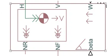
Vehicle Body Block
H port of the Vehicle Body is connected to the H ports of the four Tire(Magic Formula) Blocks. Via this ports the thrust developed by the tires is transferred to the vehicle.The NR port of the vehicle body Block is connected to the N ports of the Tire(Magic Formula Blocks) depicting Tires of the rear end of the vehicle and the NF port of the Vehicle Body Block is connected to the N ports of the Tire(Magic Formula) Blocks that depict the tyres at the front end of the vehicle.Via this ports, normal force is applied on the tire.
The V port of the Vehicle Body block is output port from which we can get the velocity of the vehicle for the given parameters and simulayion time. Further the physical signal emanating from this port is further branched into two signals.One signal is connected to an integrator block from which we would get the displacement/distance covered by the vehicle body and the other physical signal would give give the velocity of the body.
The Parameters set for the Vehicle Body Block is shown below:
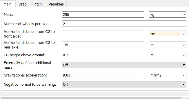
Vehicle Body Block Parameters
Input for this Objective:
Throttle and Brake Input via Signal Builder Block:
CVT Gear Ratio Input also via the Signal Builder Block:
Outputs after running the simulation for this Objective:
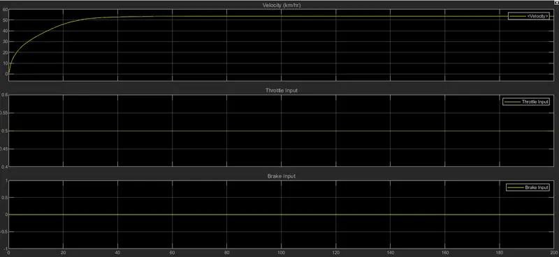
Vehicle Velocity Output for the given Brake & Throttle input:
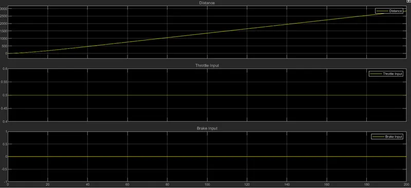
Distance covered by the Vehicle for the given Brake & Throttle Input:
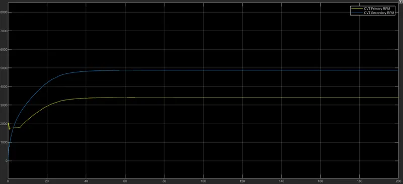
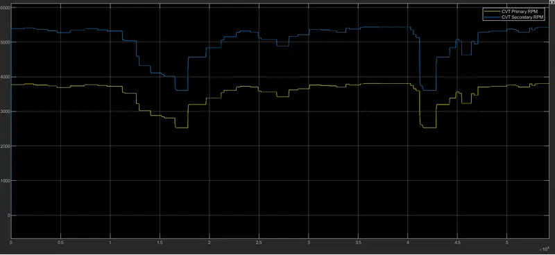
The RPM of CVT’s Primary & Secondary Shafts:
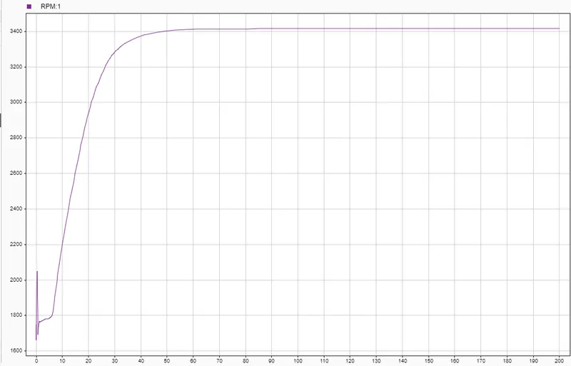
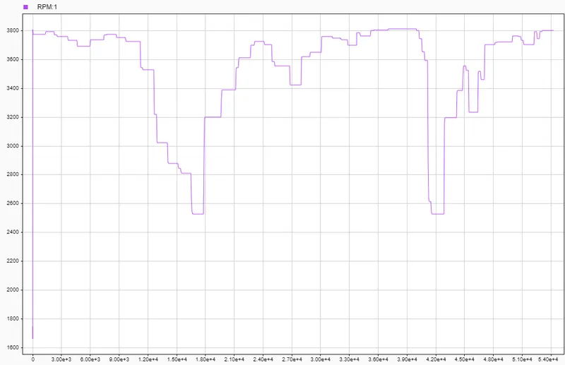
The Engine Speed for the given Throttle Input:
1.2) Solution to Objective:Carrying out System Level Simulation and preparing a Technical Report for a BAJA All-Terrain-Vehicle where Throttle Input and Brake input is fed to the system using Knob Blocks and real-time Output can be seen on the Custom Gauge Blocks. This system of Custom Gauge Blocks and Knob Blocks make up the Dashboard.
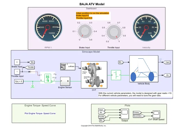
Simulink Model for simulating a BAJA ATV Model with user defined input given via the knobs in the Dashboard
Now a model very similar to the previous model is shown below. The only difference between these model and the previous model is the means by which input is fed to the system. In the previous model, the input was fed to the system using Signal Builder Blocks wherein which the user can create and generate input signals and feed them into the system.
But in the current model, instead of using Signal Builder Blocks to create and generate signals, the inputs wil be given using the Knob Block. The Knob Block is a Simulink Block through which we can control and vary the inputs given to the system. The Knob Blocks are connected to the Constant Blocks which provide input to the system based on the values in the Constant Block. The Knob controls the values in the constant Block based on the user’s controls on the Knob Block.
Along with the Knob Blocks for controlling the Brake and the Throttle input, we also have two Custom Gauge Blocks. One Custom Gauge Block is connected to the output signal from the Vehicle Body Block that corresponds to the the Velocity of the Vehicle Body. Another custom gauge block is connected to the Output Signal emanating from the W port of the RPM Sensor block of the Engine Sensor Sub-System. This signal correspnds to the Engine RPM based on the Throttle Input.
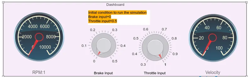
Dashboard
Varying the knobs in the Knob Blocks during simulation, the effects on the Engine RPM and the Vehicle Velocity can be directly seen on the Custom Gauge Blocks.
Rest of the setup is similar to the Model described in Objective 1.1.
Initial Conditions:
Brake Input:0
Throttle Input: 0.5
Input for this Objective:
Throttle and Brake Input via Knob Block:
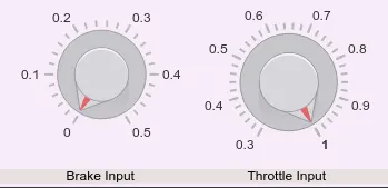
The Knobs are moved according to the user to give the required input
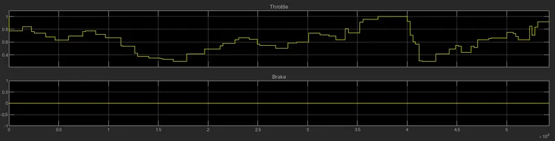
Brake and Throttle Input given by the user
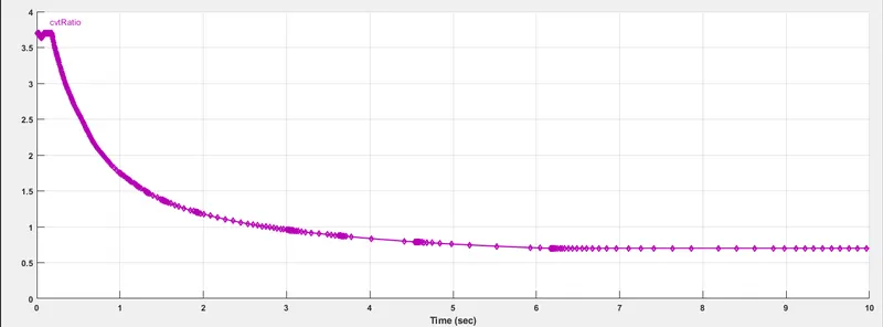
CVT Gear Ratio Input also via the Signal Builder Block:
Outputs after running the simulation for this Objective:
Vehicle Velocity and Distance covered by the vehicle for the given Brake & Throttle input & Simulation Time:
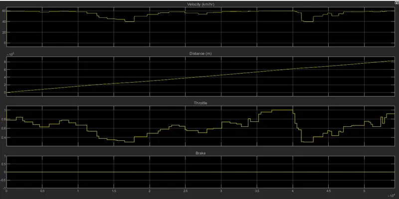
The RPM of CVT’s Primary & Secondary Shafts:
The Engine Speed for the given Throttle Input:
2.1) Solution to Objective:Carrying out System Level Simulation and preparing a Technical Report for a BAJA All-Terrain-Vehicle where Throttle Input and Brake input is fed using Step Blocks and the CVT Gear Ratio is fed to the CVT Sub-System using a Lookup Table.
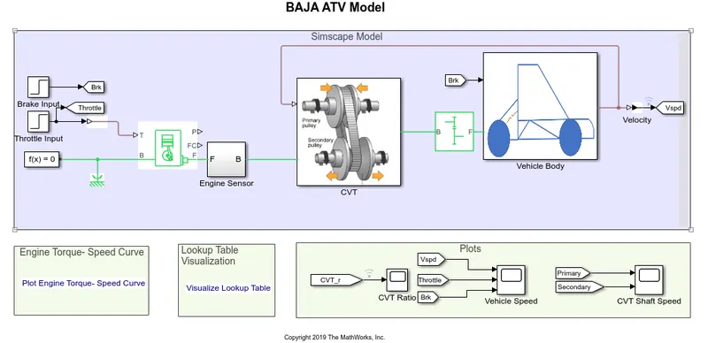
Simulink Model for simulating a BAJA ATV Model where user inputs are given using Step Blocks and CVT Gear Ratio Input are given using Data loaded in workspace through the PS Lookup Table Block and CVT Gear Ratio generated using the vehicle Velocity signal emanating from Vehicle Body Block
Though the previous models gave the reuired output but technically some aspects were bypassed. For example the CVT Gear Ratio was being defined by the user but in reality the CVT Gear Ratio is a function of the vehicle speed.
In the model the signal emanating from the Vehicle Body subsystem as an output representing the vehicle velocity is now directed back towards The CVT subsystem as an input signal. This velocity signal now goes to the PS Lookup Table block as an input signal and is then fed to the Variable Gear Ratio block of the subsystem.
- PS Lookup Table: The PS Lookup Table (1D) block computes an approximation to some function f=f(x) given data vectors x and f. Both the input and the output are physical signals.
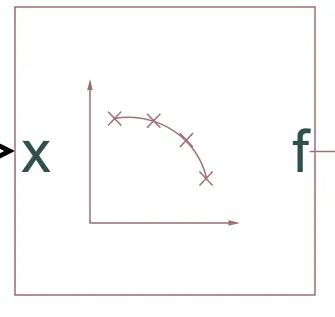
PS Lookup Table Block
The length of the x and f data vectors provided to this block must match. Also, the x data vector must be strictly monotonic, either increasing or decreasing.
A lookup table is defined by specifying the Table grid vector parameter as a 1-by-n vector (x data vector) and the Table values parameter as a 1-by-n vector (f data vector). The block generates output based on the input values using the selected interpolation and extrapolation methods. There is a choice of two interpolation methods and two extrapolation methods. There is also an option for the block to issue an error if the input signal value is outside the table grid vector range.
For this particular model, we have the data for the Vehicle Speed and the corresponding CVT Gear Ratio in the form of vectors in separate MATLAB Files. This data is loaded into the MATLAB workspace.
After loading this data into the MATLAB Workspace, we have to fill up the parameters in the PS Lookup Table.In the ‘Table Grid Vector’ parameter, we assign the values that Lookup Table will use as independent values. In this case the independent values are the values represented by the data present in ‘vehicle_speed’ and each of these data entry is divided by 6. Therefore each of the data point of ‘vehicle_speed’ vector, divided by 6 are to be used as independent values for the the Lookup Table. Now in the ‘Table Values’ parameter, we assign the corresponding dependent values for the data present in the ‘Table Grid Vector’ i.e. the values which will be the function of the values represented by data in the ‘Table Grid Vector’. The data points for these parameter are represented by the values present in the workspace variable named ‘cvtr’.Threfore the independent variable for the function is represented by the values corresponding to the variable ‘vehicle speed’ divided by 6 and the corresponding function values for this data is represented by the values corresponding to the variable named ‘cvtr’.
Now whatever be the input signal to the Lookup Table, the Lookup Table Block will use the data assigned to it’s parameters as reference and return the function value for the corresponding input value by comparing the input data to the data assigned in the parameters.
Note that the file ‘Lookuptable_data.mat’ needs to be loaded in the workspace before running the simulation.
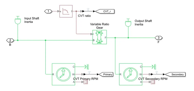
CVT Subsystem where CVT Gear Ratio data is fed to the Variable Ratio Gear using the Lookup Table Block
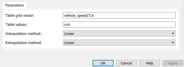
Lookup Table Parameters Assigned
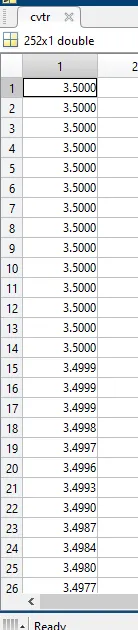
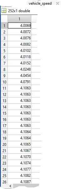
cvtr Data used in the PS Lookup Table Block vehicle_speed used in the PS Lookup Table Block
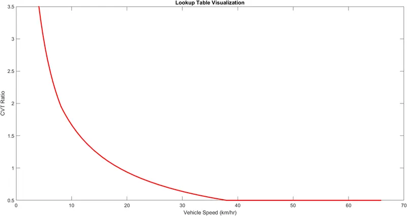
CVT Ratio-Vehicle Speed Curve as per data assigned to the PS Lookup Table Block.
Input for this Objective:
Throttle and Brake Input via Step Block:
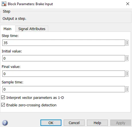
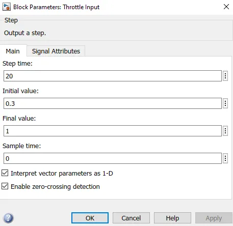
Parameters for generating the Brake Input Signal Parameters for generating the Throttle Input Signal
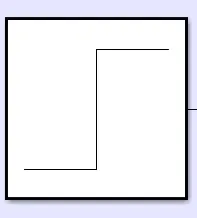
Step Block
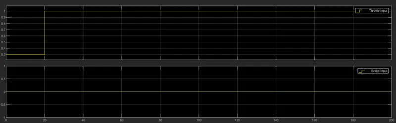
Throttle & Brake Input as generated by the Step Blocks
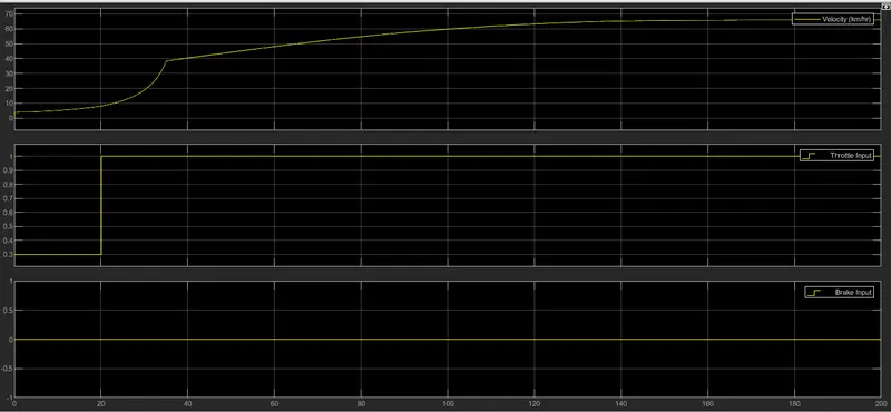
Outputs after running the simulation for this Objective:
Vehicle Velocity Output for the given Brake & Throttle input:
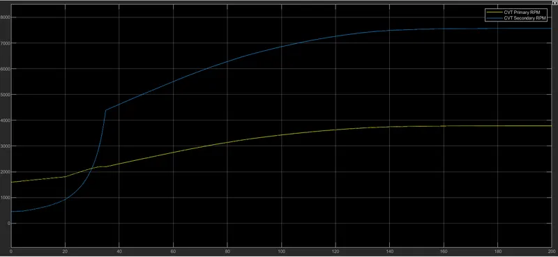
The RPM of CVT’s Primary & Secondary Shafts:
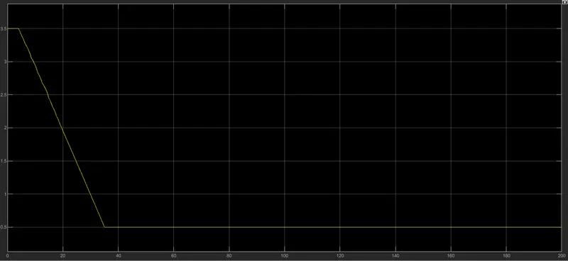
CVT Gear Ratio generated as output Signal from the Lookup Table Block as per input signal(corrsponding to Vehicle Velocity) coming directly from the Vehicle Body Block of the Vehicle Subsystem:
The Engine Speed for the given Throttle Input:
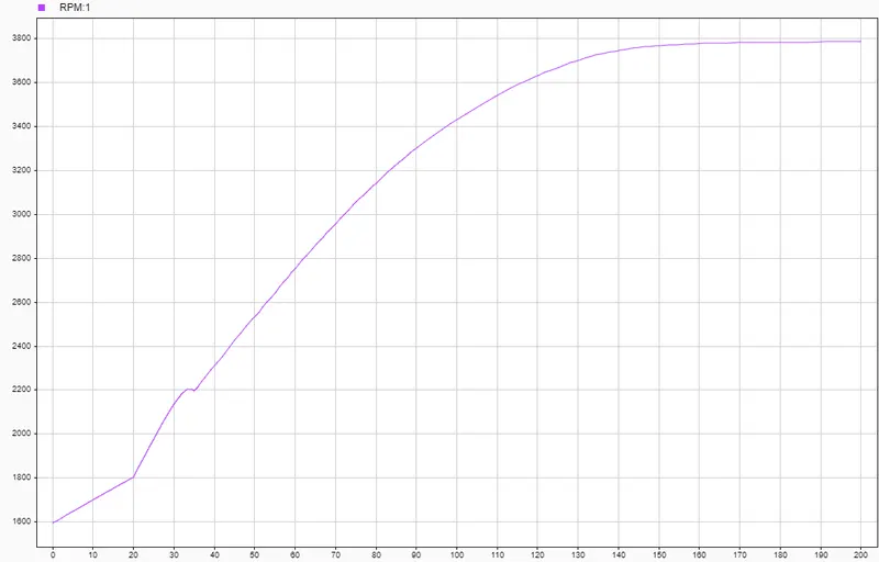
2.2) Solution to Objective:Carrying out System Level Simulation and preparing a Technical Report for a BAJA All-Terrain-Vehicle where Throttle Input and Brake input is fed to the system using Knob Blocks and real-time Output can be seen on the Custom Gauge Blocks and the CVT Gear Ratio is fed to the CVT Sub-System using a Lookup Table.
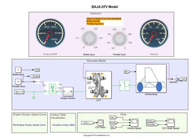
Simulink Model for simulating a BAJA ATV Model where user inputs are given using with user defined input given via the knobs in the Dashboard and CVT Gear Ratio Input is given using Data loaded in workspace through the PS Lookup Table Block and the vehicle Velocity signal emanating from Vehicle Body Block
Now a model very similar to the previous model is shown below. The only difference between these model and the previous model is the means by which input is fed to the system. In the previous model, the input was fed to the system using Step Blocks.
But in the current model, instead of using Step Blocks to create and generate signals, the inputs will be given using the Knob Block. The Knob Block is a Simulink Block through which we can control and vary the inputs given to the system. The Knob Blocks are connected to the Constant Blocks which provide input to the system based on the values in the Constant Block. The Knob controls the values in the constant Block based on the user’s controls on the Knob Block.
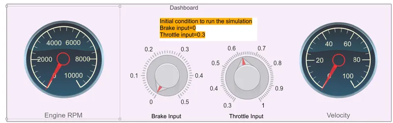
Dashboard
Along with the Knob Blocks for controlling the Brake and the Throttle input, we also have two Custom Gauge Blocks. One Custom Gauge Block is connected to the output signal from the Vehicle Body Block that corresponds to the the Velocity of the Vehicle Body. Another custom gauge block is connected to the Output Signal emanating from the W port of the RPM Sensor block of the Engine Sensor Sub-System. This signal correspnds to the Engine RPM based on the Throttle Input.
Varying the knobs in the Knob Blocks during simulation, the effects on the Engine RPM and the Vehicle Velocity can be directly seen on the Custom Gauge Blocks.
Rest of the setup is similar to the Model described in Objective 2.1.
Initial Conditions:
Brake Input:0
Throttle Input:0.3
Input for this Objective:
Throttle and Brake Input via Knob Block:
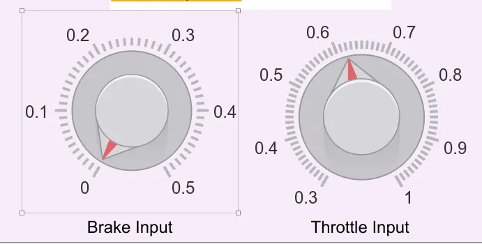
Knob Blocks through which user can give and modify the inputs during Simulation time
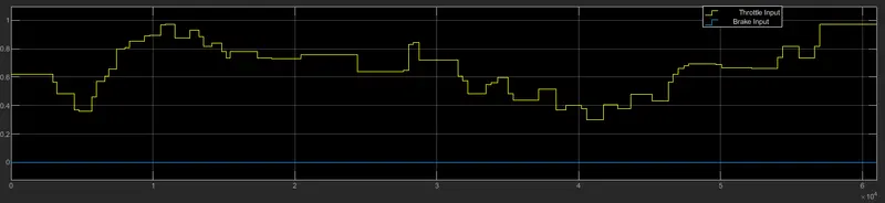
Throttle & Brake Input given by user according to variation made using the Knob Blocks
Outputs after running the simulation for this Objective:
Vehicle Velocity Output for the given Brake & Throttle input:
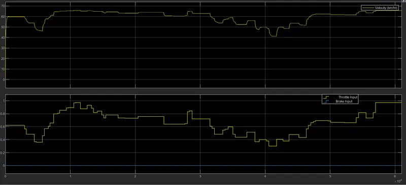
CVT Ratio Output Signal as per the Velocity output generated from the Vehicle Body Block:
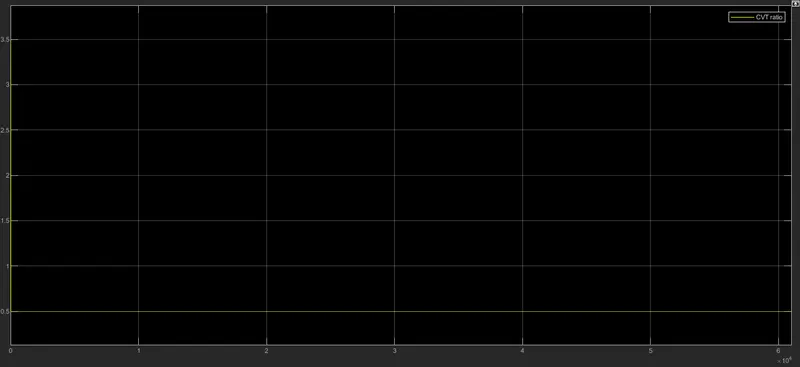
The CVT Gear Ratio remains descends from 3.5 to 0.5 at time=0 and remains constant at 0.5 for the rest of simulation time
The RPM of CVT’s Primary & Secondary Shafts:
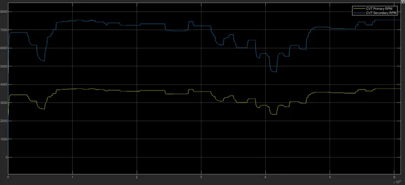
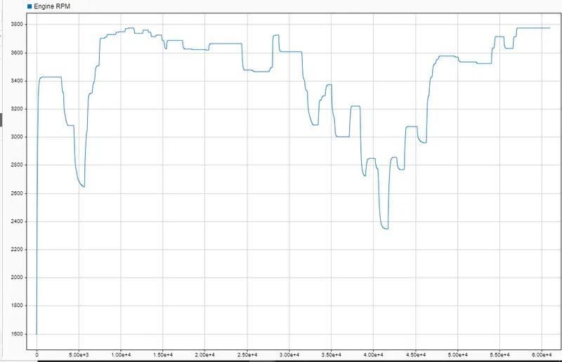
The Engine Speed for the given Throttle Input:
CONCLUSION:
The BAJA ATV Model was simulated successsfully and the following can be inferred:
- Vehicle Velocity, CVT Shaft Speed and Engine Speed(RPM) is directly proportional to the Throttle input.
- CVT Ratio is directly proportional to Torque and inversely proportional to Throttle input.
- CVT Primary Speed is greater than CVT secondary Speed as they are directly proportional to Shaft Diameter.
REFERENCE:
https://www.mathworks.com/matlabcentral/fileexchange/70576-baja-all-terrain-vehicle-atv-model