Project
Baja All Terrain Vehicle
Aim:
To study and analyze the working of the baja all terrain vechicle with its model design in the simulink.
Introduction:
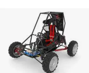
ATV or All Terrain Vehicles are a vehicle that travels on low-pressure tires, with a seat that is straddled by the operator, along with handlebars for steering control. As the name implies, it is designed to handle a wider variety of terrain than most other vehicles.A lot of Dune bashing/Racing used to take place in the sand dunes of Baja California and these races came to be known as Baja Races. Now to adopt with these dunes specific modifications were made to cars iconic amongst which was the Baja Bug which was nothing but a VW Beetle modified for the Baja Dunes.
In 1976 the University of Southern California held the first ATV event which was named Baja SAE keeping in mind the popularity of the races in the Baja Dunes at that time. As time progressed the event became quite famous and the ATVs that were made for the purpose of the competition began to be referred to as Bajas.
Simulink model:
The simulink model for the AVT is of two types,one without dashboard and the other with dashboard.First we can take a look at the model without dashboard.
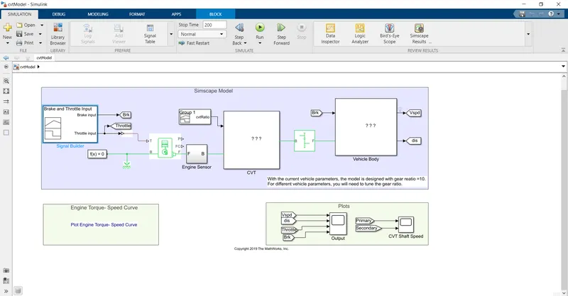
The main blocks used in the model are,
1.Signal builder
2.Genric engine
3.Engine sensor subsystem
4.CVT subsystem
5.Simple gear
6.Vehicle body subsystem
7.Scope
1.Signal builder:
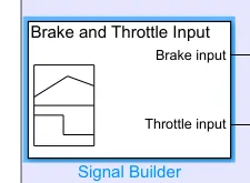
The signal buillder is used to give the input signals like acceleration and brake signals to the vechicle.The brake signal is given to the vehicle body system.The acceleration signal is given to the engine block.
In this model the acceleration is taken a constant of one and the brake takes a constant of 0 value.
2.Generic engine:
The engine block represents the combustional engine of the vehcile.It has 5 ports,Two input port ,one output port and two ports for graphical viewing of outputs.
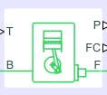
T port- It is used for getting input from the signal builder.The acceleration signal is connected with this port.
B port- It is usually connected to the ground.Here it is connected to the mechanical referance.
F port - It act as the output port producing the required force from the engine which is used to rotate the shaft.It is connected to the engine sensor subsystem.
3.Engine sensor subsystem:
The subsystem is used to configure the position and the rotation of engine graphically without affecting the actual flow the energy.
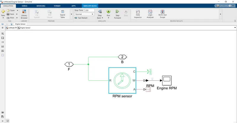
The subsystem consists of the above blocks.The output of the engine is taken as the input to the subsystem.The same is made available as the output of the system along with connecting it with a motion sensor to detect the rotation of the engine .The output of the sensor block is given to the scope.
4.CVT subsystem:
A Continuously Variable transmission (CVT) is an automatic transmission that can change seamlessly through a continuous range of gear ratios. This contrasts with other transmissions that provide a limited number of gear ratios in fixed steps. The flexibility of a CVT with suitable control may allow the engine to operate at a constant RPM while the vehicle moves at varying speeds.
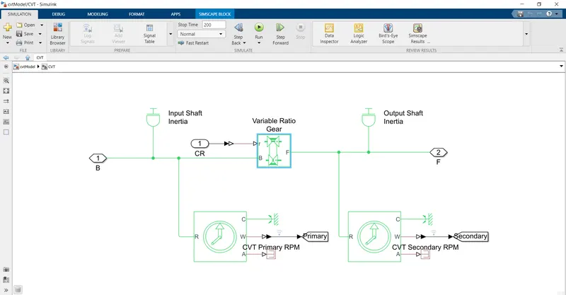
The above model is used to implement the cvt nature to the vehicle.It contains variable ratio gear and some sensor and inertia.
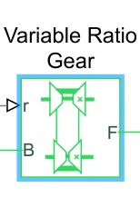
The engine force is taken as the input and given to the varaible gear ratio which has three ports.The input port B is connected with the engine force.
It also contains a referance input r port ,a referance signal is created using the signal builder and it is given to the port.
The output F port is taken as the output of the subsystem which is connected with the gear box.
The motion sensor and inertias are placed before and after the ratio gear block to check the change in the shaft produced by the gear ratio.
5.Simple gear:
This block contains two ports,B-input port and F-output port.

The output from the cvt subsystem is given as the input to the B port and the output from the F port is given to the vechicle body subsystem.
6.Vehicle body subsystem:
This subsystem comprises of the nature of the moving vehcile body and in its parameters like air drag,hill climbing and body mass.
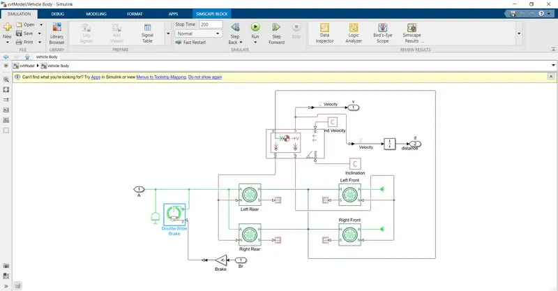
The above is the blocks in the vechicle subsystem.So the subsystem comprises of ,
1.Double shoe brake
2.Wheel
3.Vehicel body
Double shoe brake:
This block is used to reduce the speed of the shaft.IT contains one input and one output port.
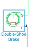
- F port- It is the input port which is connected with the brake signal from the signal builder.
- S port - It is the output port which is connected with the shaft of the vechicle to apply the deceleration to the wheel.
Wheel:
Here we used the tyre block(magic wheel)block to make our wheel for the EV.The block has 4 ports namely A,N,S,H.
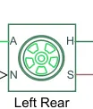
A port - It is Mechanical Rotational conserving port for wheel axle.The wheels in the same axle should be connected through this port.
N port - It is the normal reaction acting on it.This port is connected with the vechicle body block.
H port - It is Mechanical Translational conserving port for the wheel which produce the thrust developed in it .The 4 wheels are connected though this port and this port is also connected to the same translational port in the vechicle body port.
S port - It is the Slip output of the wheel .Here it is left unconected or it can be connected to a ps terminator which is used for no connection port.
The block is characterized by various block parameters,
- Peak longitudinal force is set to3000N
- The Slip is set to 10%
- The Tyre radius is given as 0.3m
- The wheel inertia is kept at 1Kgm^2
- The rolling coefficient is kept as 0.015
This tyre block is connected with the vechicle body simscape block
Vehicle Body:
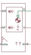
The vechicle body block is used to connect the wheel to real world vechicle.It consist of NR,NF,beta,V,H,W block
Nf-Nr - They are output port for normal reaction connected to the front and rear wheels of the EV.
H port- It is the Mechanical translational conserving port connected to the H port of wheel.
V port - It is the actual output velocity of the vechicle which is send to scope to view the output graph after the simulation.
beta - It is the road inclination angle.Here it is considered as constant 0 value.
W port- It is the head wind speed.Here it is considered as constant 0 value.
The parameters of the block are changed in order to control the aerodynamic drag force,body mass and road inclination distributed between the wheel axle.
- The gross weight is taken as 1200kg
- The geometric parameters are kept constant
- Drag coefficient is taken as 0.3
- The pitch dynamics for the vechicle are not considered.
Simulation:
The model setup is done and now we have to run the simulation to see the results of the scope block.
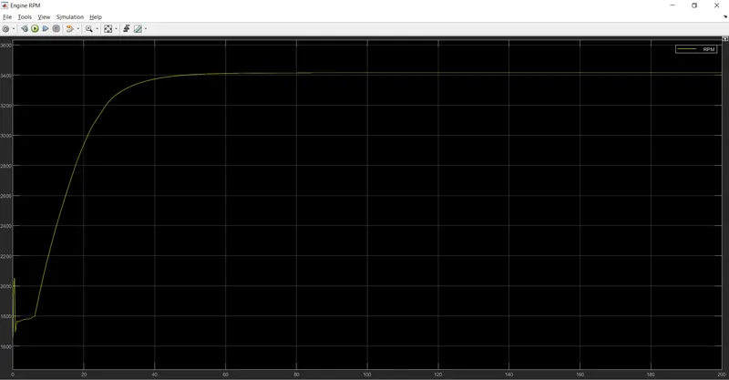
The above graph is the output of the engine rpm.We can see that hte engine rpm is initially at 1800 rpm and after 40s it increased to 3400 rpm and maintained there for the remaining time.
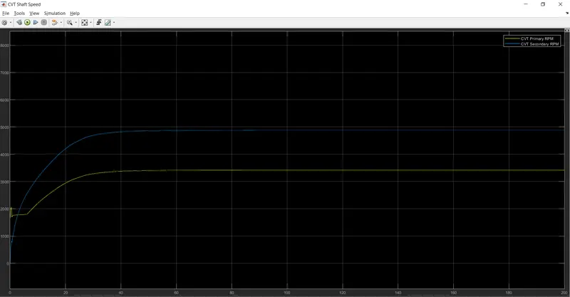
The above graph is the result of CVT blocks .It is clear from the graph that the secondary shaft rpm is greater than the primary shaft rpm but the initailly value is lesser for the secondary shaft.
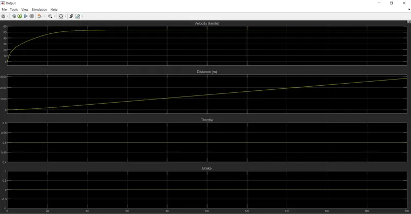
The above graph shows the necessary output of the vehicle .The velocity of the vehcile follows the the path of the engine rpm.The distance tends to increase as the velocity is only in the positive direction.
The input values like throttle and the brake is also shown in the graph .The throttle tends to remain at 0.5 and the brake value remains 0.
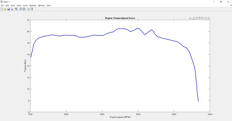
The above graph shows the relation between speed and the torque of the engine.The torque tends to increase with the increase in the speed .After a particular value the torque tends to decrease.