Project
Aim: Continuously Variable Transmission
A continuously variable transmission (CVT) is an automatic transmission that can change seamlessly through a continuous range of gear ratios. This contrasts with other transmissions that provide a limited number of gear ratios in fixed steps. The flexibility of a CVT with suitable control may allow the engine to operate at a constant RPM while the vehicle moves at varying speeds.
CVTs are used in cars, tractors, side-by-sides, motor scooters, snowmobiles, bicycles, and earthmoving equipment.
The most common type of CVT uses two pulleys connected by a belt or chain; however, several other designs have also been used at times.
Construction of CVT gearbox
CVT being an automatic does almost all of the work on its own requiring no driver input. Every type of transmission has a set number of gears and gear ratios. The gear ratios are dependent on the speed and RPM of the car. CVT’s have a major difference in these criteria.
CVT’s are unique in this aspect because they don’t have gears instead it has pulleys. With its pulley system in place, CVT’s are able to achieve an infinite number of gear ratios. This infinite number of ratio allows it to have a gear shift at even 1 mm of belt movement of the pulley system.
Working of CVT Gear box:
One the pulley is connected to the crankshaft (driving shaft) while the other is connected to the drive shaft (driven shaft). A V belt is free to move around the pulleys. ECU controls the movement of the pulley electronically.
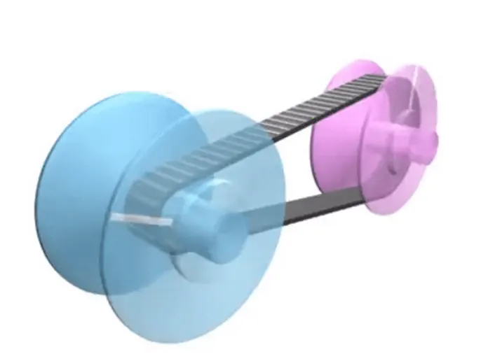
Using the image above as reference we can see how CVT works. Take the example of a low gear setting. In this example, let’s say the blue shaft will move three times for every one pink shaft rotation. This in terms of gear ratio can be explained as a gear ratio of 3:1. Now if it were high gear this would simply reverse the order and blue will move slower.
The width of the pulley changes according to the speed of driving and they are inversely related to each other. When one pulley grows bigger the other one gets shorter.
The biggest reason for CVT’s having better efficiency is the pulley system. With its pulley system, the gear ratio is always kept at the perfect position to provide maximum output on that specific RPM. This means there is no extra fuel spent. Furthermore, the engine is kept at lower revs during cruising speed and is instantly provided more power if the car is accelerated thus having no delay in the power supply or gear shift at all. This gives it both a smooth ride and a good fuel efficiency.
This is the reason that CVT’s have better efficiency compared to other options like DCT or AMT.
Advantages Of CVT
It offers a smooth ride compared to a manual.
It provides more fuel efficiency than other transmission systems.
Easier to use while performing tasks like driving uphill.
They are quite light compared to other transmissions.
Disadvantages Of CVT
Because of how it works it has slow acceleration.
It provides no output to the driver thus feeling a little bland to drive.
Expensive to replace and repair compared to other transmission systems.
CVTs are limited in what engines they can work with.
CVT model by using SIMSCAPE:
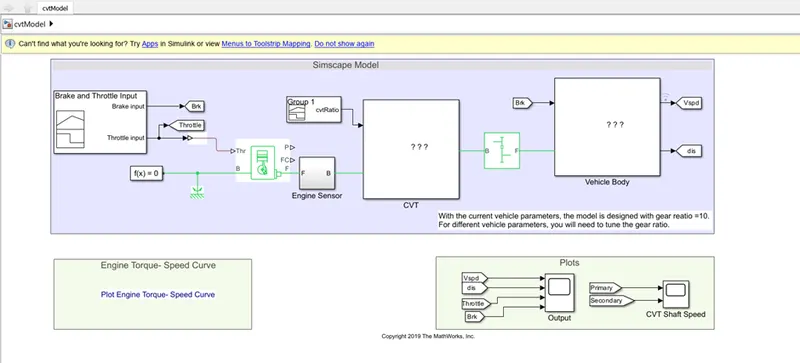
CASE 1:
In above CVT model, we make changes on input parameter like Brake input and Throttle input Signal builder block.
- Here, we keep Throttle inputs values as 0.7 and brake input as 0 means brake pedal not engaged condition and only 70% accelerator pedal pressed.
|
CASE 1 |
||
|
Time |
Throttle Input |
Brake Input |
|
0 |
0.70 |
0 |
|
10 |
0.70 |
0 |
|
20 |
0.70 |
0 |
|
30 |
0.70 |
0 |
|
40 |
0.70 |
0 |
|
50 |
0.70 |
0 |
|
60 |
0.70 |
0 |
|
70 |
0.70 |
0 |
|
80 |
0.70 |
0 |
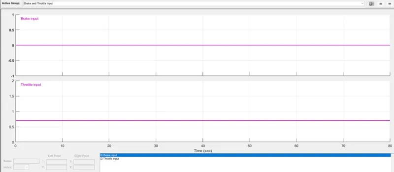
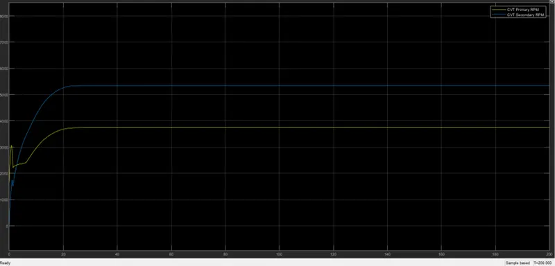
- After simulation, we observed that velocity increase up to 60 kmph and keep constant as respective to as throttle input constant.
- As velocity increases, distance increases up to 3000 m.
- As per CVT graph, during primary condition of CVT, vehicle RPM goes up to below 4000 RPM.
- During secondary condition of CVT, vehicle gets maximum above 5000 RPM.
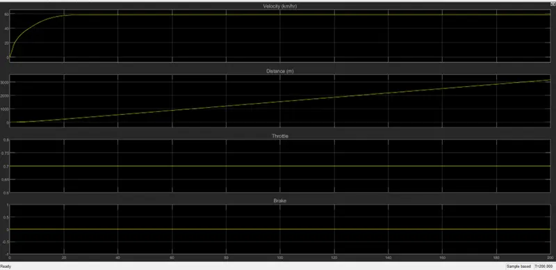
CASE 2:
In above CVT model, we make changes on input parameter like Brake input and Throttle input Signal builder block.
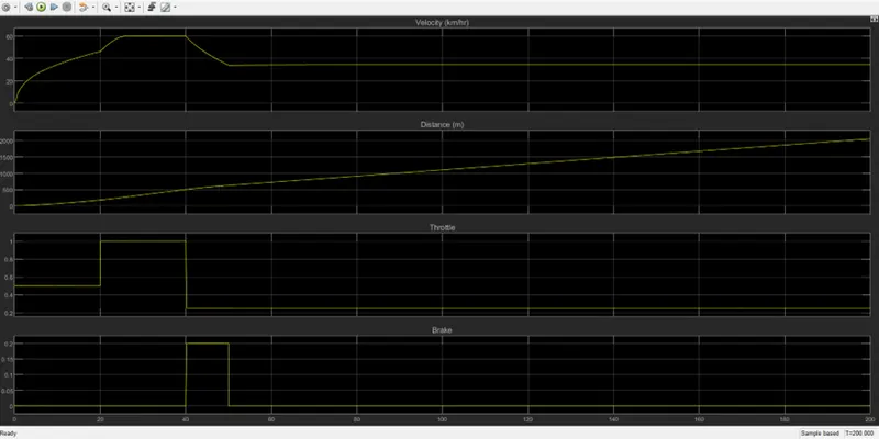
- Here, we keep Throttle inputs values as 0.50, 1.00, 0.25 and brake input as 0 & 0.2.
- Means from starting throttle inputs gives 50% throttle and after 20 second, throttle pedal increases up to 100%. At 40 second time, brake pedal pressed 20% till 50 second times.
Because of brake input, throttle input decreases to 25%.
|
CASE 2 |
||
|
Time |
Throttle Input |
Brake Input |
|
0 |
0.50 |
0 |
|
10 |
0.50 |
0 |
|
20 |
1.00 |
0 |
|
30 |
1.00 |
0 |
|
40 |
0.25 |
0.2 |
|
50 |
0.25 |
0.2 |
|
60 |
0.25 |
0 |
|
70 |
0.25 |
0 |
|
80 |
0.25 |
0 |

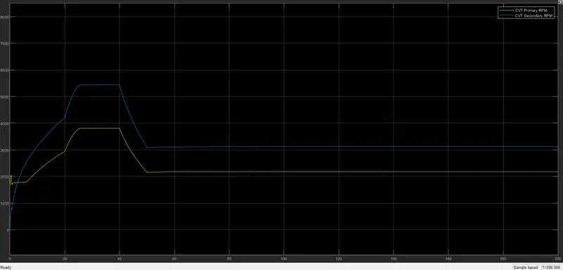
As per below output of CVT Simulink model, we observed that below points.
- As throttle input increases, velocity increases.
- As the brake input comes in to pictures velocity get decreases.
- Velocity gets contact output as Throttle input get same values.
- As throttle increase as any values, distance keep increases.
- In CVT graph, primary CVT running lower RPM speed then secondary CVT RPM.
Enclosed: CVT Simscape model