Project 2 - V&V SW Analysis II
1.Implement control logic of a “washing machine” using Stateflow
- If the power supply is available, the system gets activated
- If the Water supply is not available, stop the process & indicate through LED
- Soaking time should be 200s followed by Washing time of 100s.
- Then rinsing happens for next 20s & dryer runs for 50s
Objective:
To obtain a working logic of washing machine using stateflow
Simulink Model:
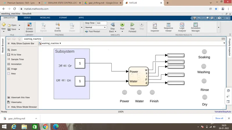
This simulink is based on the State flow control logic.
In this system,we use Chart to execute our control logic.State flow will be designed in the chart.
We are using Power ON=1,Power OFF=0;(Indicated by the lamp)
Water ON=1,Water OFF=0(Indicated by the lamp)
Each display is given to assign the value.And the lamps are assigned to individual activities.
Each lamps are connected to individual display.
Inside the Chart:
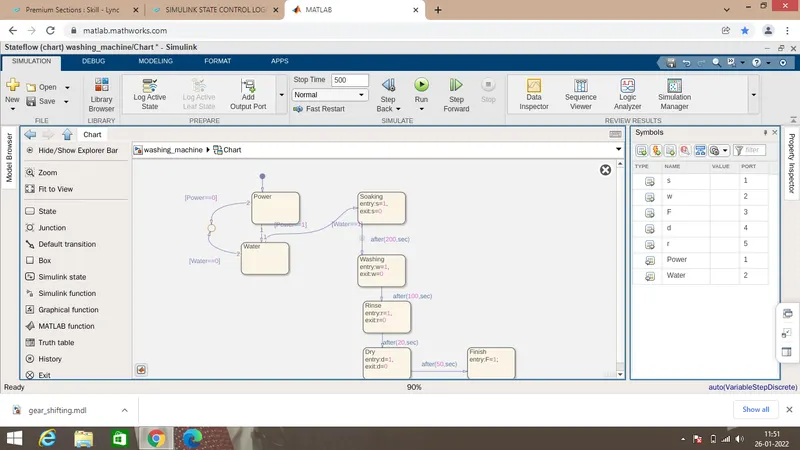
Assigned values:
Power==1;Power should be ON to activate the system,and water==1;water should be ON to activate the system.Both the condition should be satisfied.
Symbols are to be assigned to get the Input and Output ports .
If the power supply is available, the system gets activated
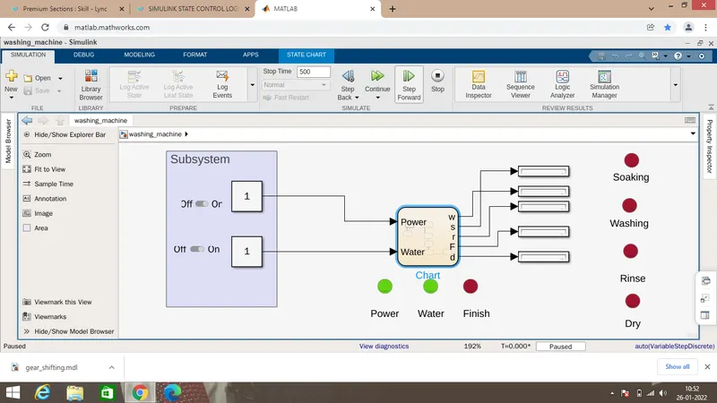
When Power is ON the system gets Activated.
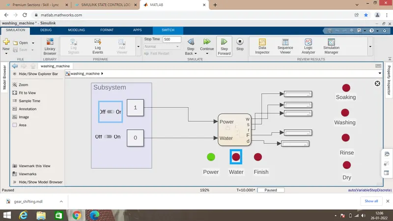
If the Water supply is not available, stop the process & indicate through LED:
If the water is not available ,the indicator will indicate in brown colour and the process will stop
Soaking time should be 200s
If the water is available ,the the process will start and the soaking process started.
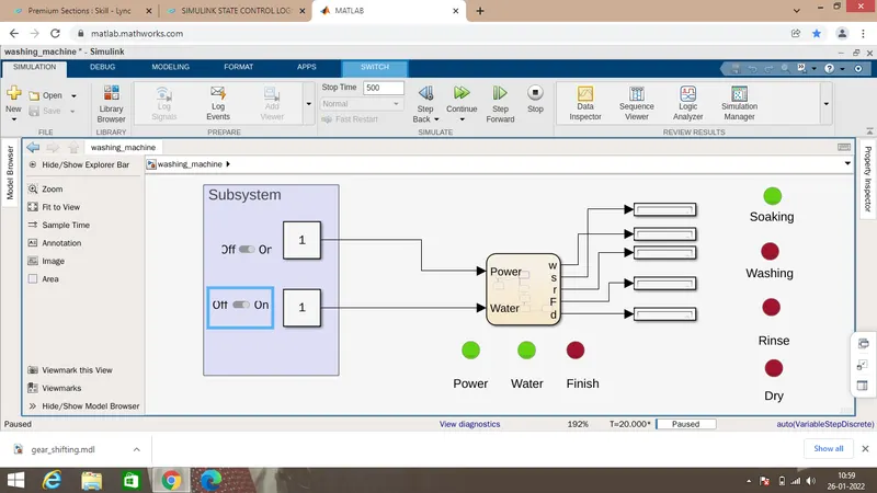
After 20 secs,Soaking will start.For 200secs,the soaking will happen.
Washing for 100secs:
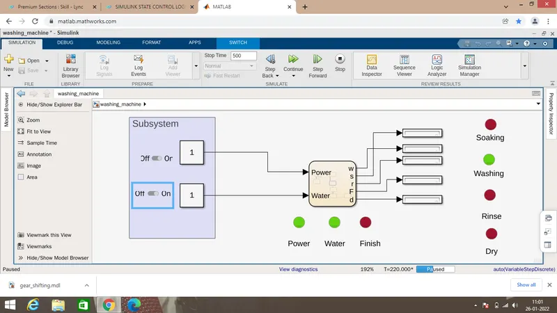
Washing Process started and continuous for 100secs
Rinse process for 20secs
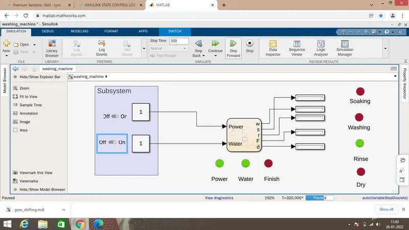
Dry for 50secs:
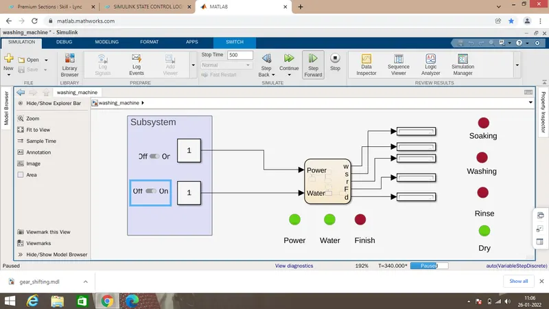
After Dry-the Process is Finished and indicated by Lamp:
After the process over,Finish signal is indicated by lamp
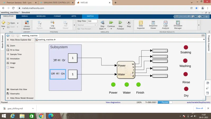
If Power is OFF-No process will happen;
if water is not available,the process is stop and we can check at the 40th sec, whether the soaking is happening or not:
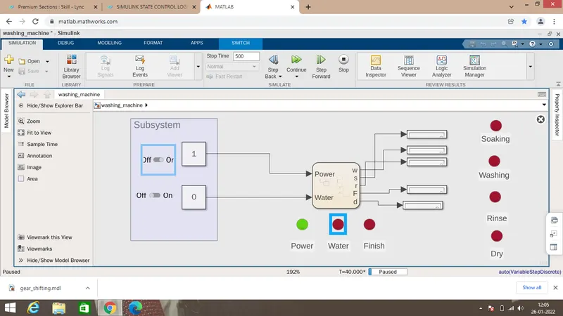
As a result no process is started.
Make a Simulink chart for the “Gear shift” logic
Speed Range(kmph) Gear
0 to 15 1
16 to 25 2
26 to 40 3
41 to 60 4
Above 61 5
Objective:
This simulation is to check the gear shift according to the speed .
Simulink Model
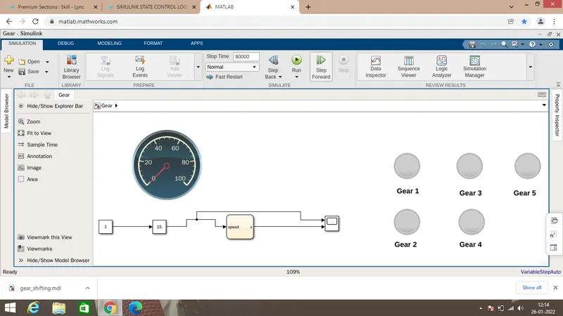
In this model,Lamps are used to indicate the gear position respective to the speed.
Slider gain is used to input the different speed as an input signal.
Speedometer is used for monitoring the speed.
Inside the Chart
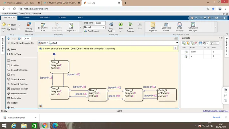
From Speed range-0 to 15
When Speed ranges from 0 to 15-Gear 1 get shifted
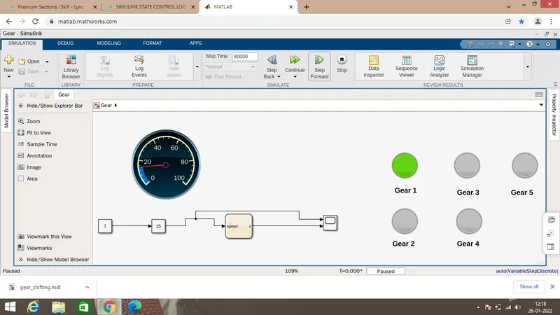
Gear lamp 1 indicate the Gear position.
Speed from 15 to 25kmph
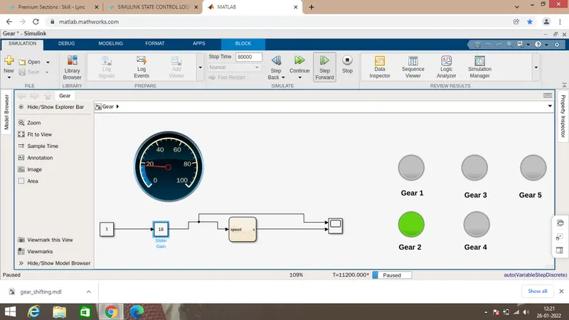
When the speed ranges from 15 to 18kmph ,the gear 2 get shifted
When the Speed ranges from 25 to 40kmph
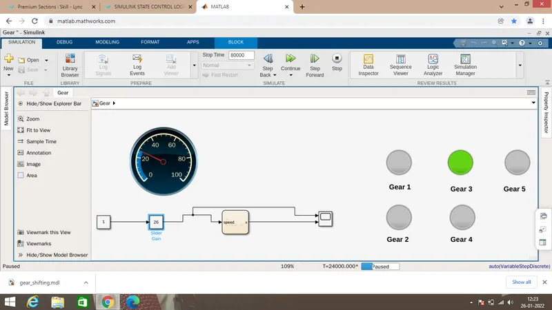
when the speed crosses above 25kmph,the gear shifted from 2 to 3rd position.
Speed range between 40 to 45kmph
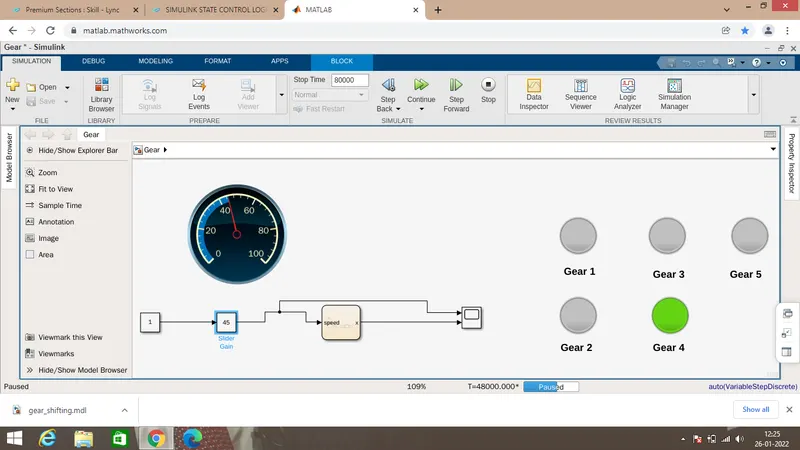
when it crosses 40kmph, gear shifted to 4th gear.
Speed above 60kmph
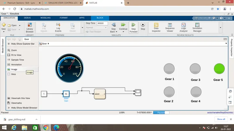
When it reaches above 60 kmph, 5th gear activated.
when the speed decreases from 61 to 50kmph,
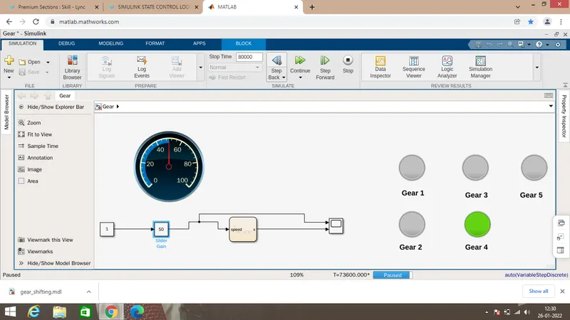
Gear shifted from 5th to 4th, when the speed decreases.
When the speed decreases to 22kmph
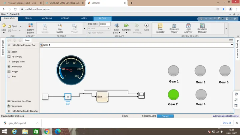
the gear shifts gradually from 4th to 3rd and then to 2nd.
Scope
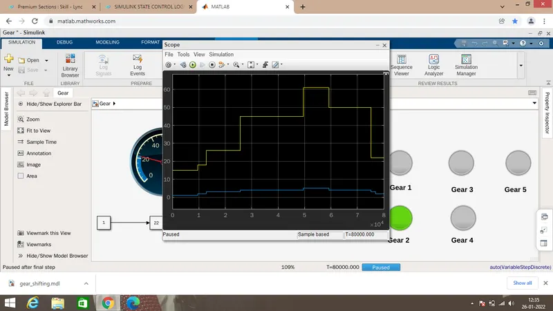
The gear shift operation is successful, as the gear shifts happens for different speeds