Project 2 Thermal modeling of battery pack
The following figure shows the simulink model of 10 cell series lithium-ion battery using AC Current source providing cyclic charge/discharge profile . This is the base model in which we need some modifications .
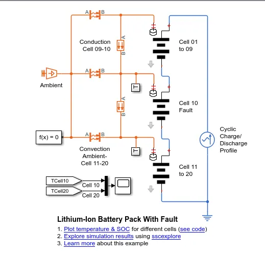
The blocks which are already there and the blocks we are going to implement in the above model with their modified parameters are as follows ,
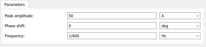
a) AC Current Source - It represents an ideal current source which maintains sinusoidal current through it .
The equation for output current is given as ,
I = Io*sin(2`pi`*f*t + `omega`)
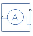
b) Current Sensor - It senses the current flowing through the circuit .
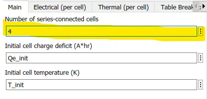
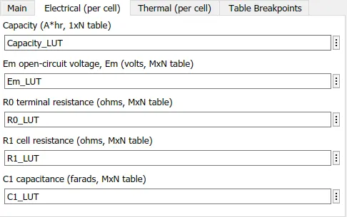
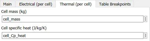
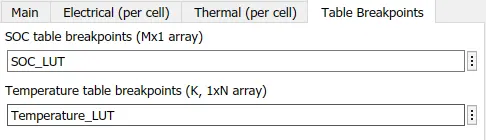
C) Lithium Cells - The cell block represents an ideal lithium ion cells used in a battery pack with thermal port . Here Cell pack 1-4 and 6-10 are healthy cells whereas Cell 5 is faulty cell .
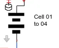
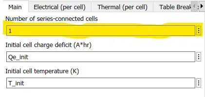
For Cell 01_04
For Cell 5
For Cells 06_10
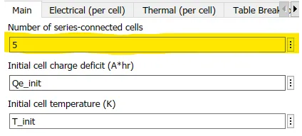
The parameter " Number of series-connected cells " have been modified for every cell pack as the modification has been highlighted with yellow colour . Rest has been kept unchanged .
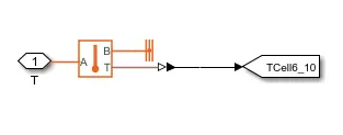
d) Temperature Sensor - This block senses the temperature between two points .

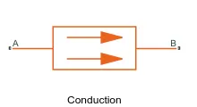
e) Conductive Heat Transfer - This model represents heat transfer in a thermal network by conduction through a layer of material . There are two conductive heat transfer in this model . One is for Cells 01_04 and other is for 06_10 . The parameters are same for both blocks .

f) Convective Heat Transfer - In this mode of heat transfer the transfering medium is liquid .
The parameter '" Area" have been modified . For Cells 01_04 ,

For Cell 5

For Cell 06_10

g) Temperature Source - It is an ideal temperature source which provides temperature to the network .

The value of T_init is given as 293.15 K .
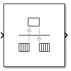
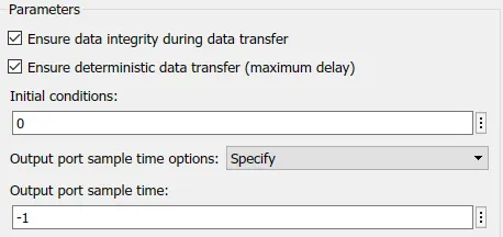
h) Rate Transition - It transfers data from output of a block at operating at one rate to input of another block operating at different rate .
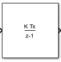
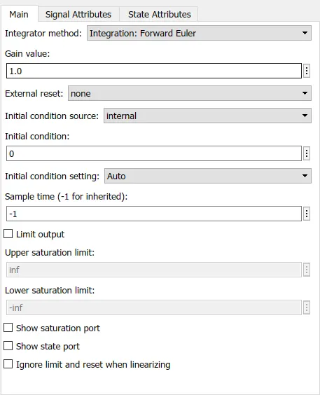
i) Discrete-Time Integrator - This block implements discrete time integration or accumulation of input signals .
j) Mux - This block combines inputs with the same data type and complexity into vector output .
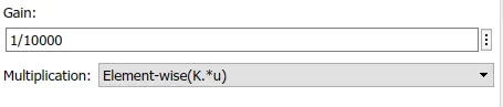
k) Gain - This block is use for multiplication . Here we have taken the gain value 1/10000 as shown in figure below .
Final Model (Modified Model) -
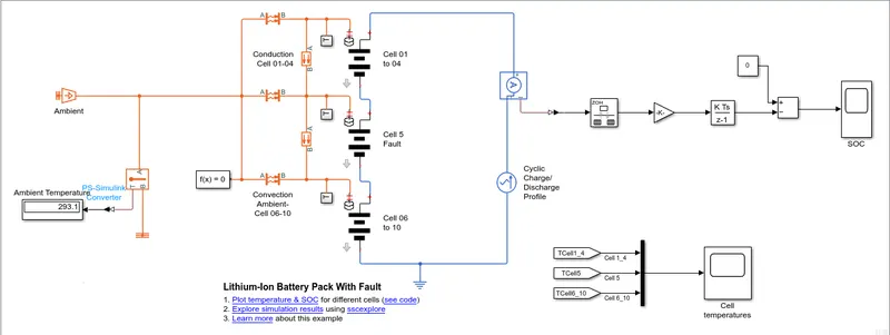
Subsytem of Cell Pack -
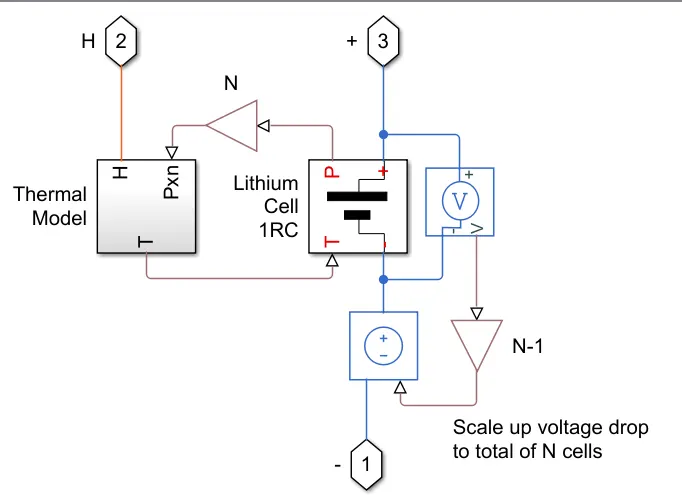
If we click on the arrow directing downward we come to see a subsytem shown below .
It consiste of two blocks ,
- Thermal Model
- Lithium Cell 1RC Model
- PS Gain Block
The role of this subsystem is to calculate the temperature and thermal effect of the cell .
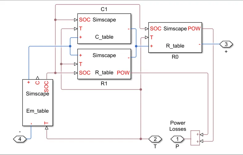
- Lithium Cell 1RC Model
It has Em block which represents the cell's main branch voltage source and determine the value of capacity and SOC .
There is one Capacitor whose value depends on external physical signal SOC and Temperature .
There is resistors R1 and R0 whose values depends on SOC and Temperature .
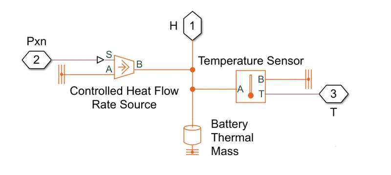
- Thermal Model
This model has three blocks ,
a) Controlled Heat Flow Rate Source which is an ideal source of energy which maintain heat flow rate regardless of temperature difference .
b) Battery Thermal Mass block reflects the ability of material to store internal engery . The parameter of this block is mentioned below .
C) Temperature Sensor which senses the temperature .
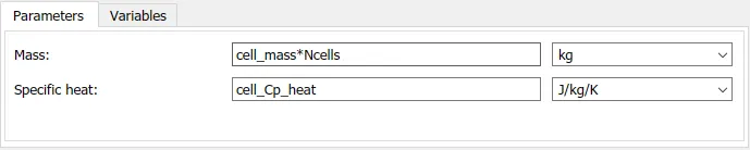
The value of cell_mass is given as 810.5328 kg .
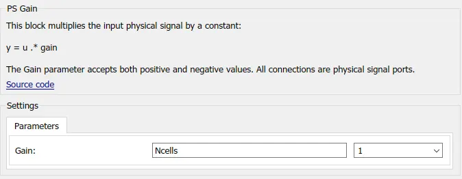
It has PS Gain block which multiplies input physical signal with number of cells .
Subsystem Used in Model -
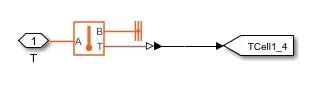
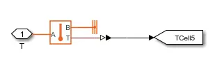
There are three subsytem used in model for each cell packs .
For Cells 01_04
For Cell 05
For Cell 06_10
Observations -
After simulating the model for 7200 seconds we get the following results ,
1) Ambient Temperature
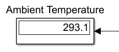
The value of ambient temperature comes out to be same as the value of T_init .
2) Cell Temperature
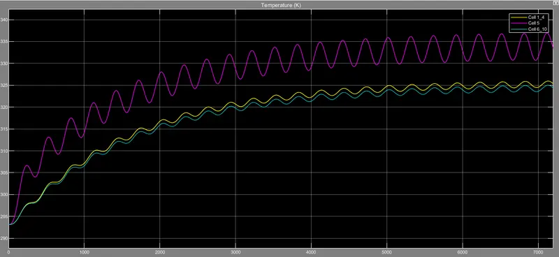
We see that , Cell 5 reaches the maximum temperature of 336 K . Cells 01_04 and Cells 06_10 attains the temperature upto 326 K and 325 K .
3) SOC and Life Cycle
We observe that ,
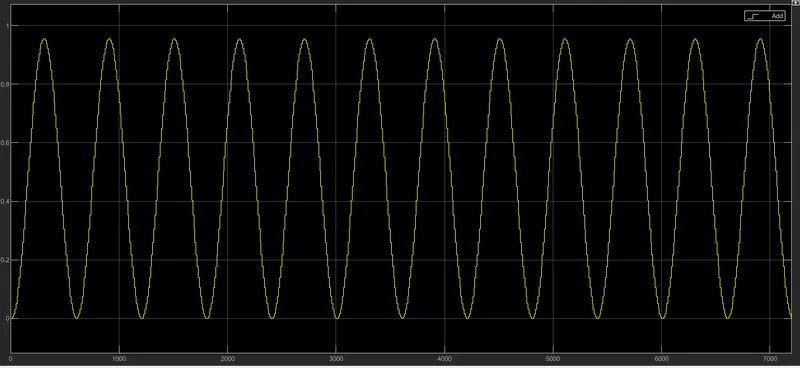
- SOC rises from 0 to 0.954 in 300 sec and then discharges to 0 in next 300 sec . And this cycle keeps on repeating upto end of the simulation .
- The Life Cycle of battery pack seems to be 6 cycles per hour .
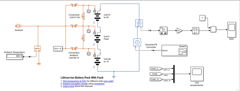
Now we are the input method . We are using UDDS Drive Cycle for giving input to the model . The modification done is we added one block that is Controlled Current source and Drive Cycle block .
The modified model is shown below ,
UDDS Drive Cycle -
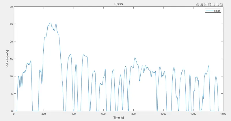
Urban Dynamometer Driving Schedule (UDDS) driving cycle is a typical urban driving cycle with average speed of 31.51km/h and has frequent braking and acceleration .
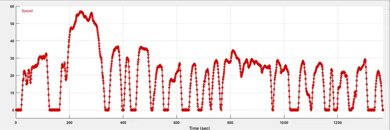
So we have imported UDDS Drive cycle data in signal builder as shown in figure below ,
Rest all the blocks and parameters are same . No changes have been done to them .
Observation -
1) Ambient Temperature remains same that is 293.1 K .
2) Cell Temperature
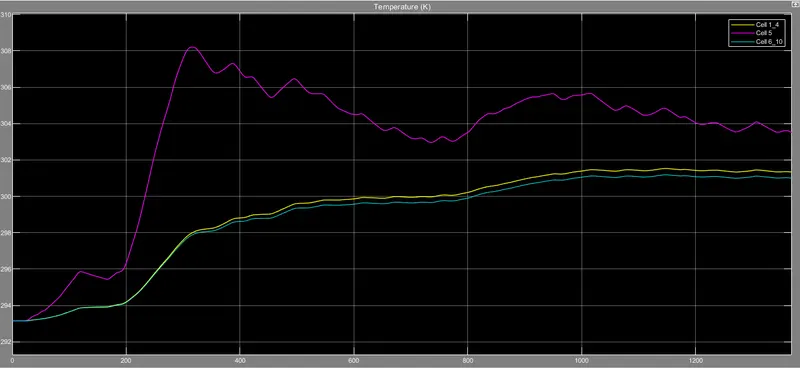
We see that Cell 5 which is faulty attains the maximum temperature of 293.2 K . The cell pack 1_4 and pack 6_10 attains the temperature 293.18 K and 293.17 K .
3) SOC and Cycle Life
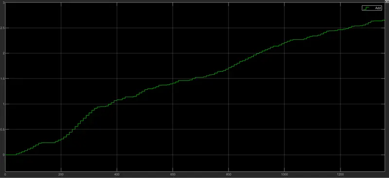
We see that ,
- SOC of the model starts from 0 and reaches upto 0.9 in 1400 secs .
- As we can see in the above plot that cycle life cannot be determine .
Hence we have simulated the 10 cell series lithium ion battery model and observe the result with some modifications in it .