Project 2 Thermal modeling of battery pack
BLOCKS USED:
Battery (table based): Battery block which can be configured with desired voltage and capacity
PS constant block: For providing constant input values of current
Controlled current source: Used to supply or draw a constant current
Constant: Used to provide a constant value
Integrator: used to integrate an input
Gain: used to mulitply the input by a factor
Add: Used to add/subtract values
Scope: Display results
Goto: To send signals which can be later called
From: Receives signal from goto block
Current sensor: Sensing current, connected in series with the battery pack
Voltage sensor: Sensing voltage connected parallel with the battery pack
Electrical reference: Reference for the electical component
Solver configuration: All simscape block require a solver configuration to work
PS-Simulink: converts physical signal to simulink signal
Temperature source: Used to supply a set temperature
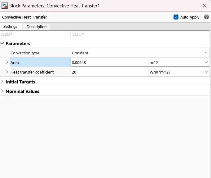
Convective Heat transfer: The temperature from the temperature source needs a medium to conduct the heat and usually heat transfer from the battery pack takes place through convection (air or liquid cooled) so we use convective heat transfer.
Temperature sensor: Senses the temperature difference between two points here one point is after the convective heat transfer block and the reference point is taken as ground.
Thermal reference: Thermal ground or reference for the thermal model
SIMULINK MODEL
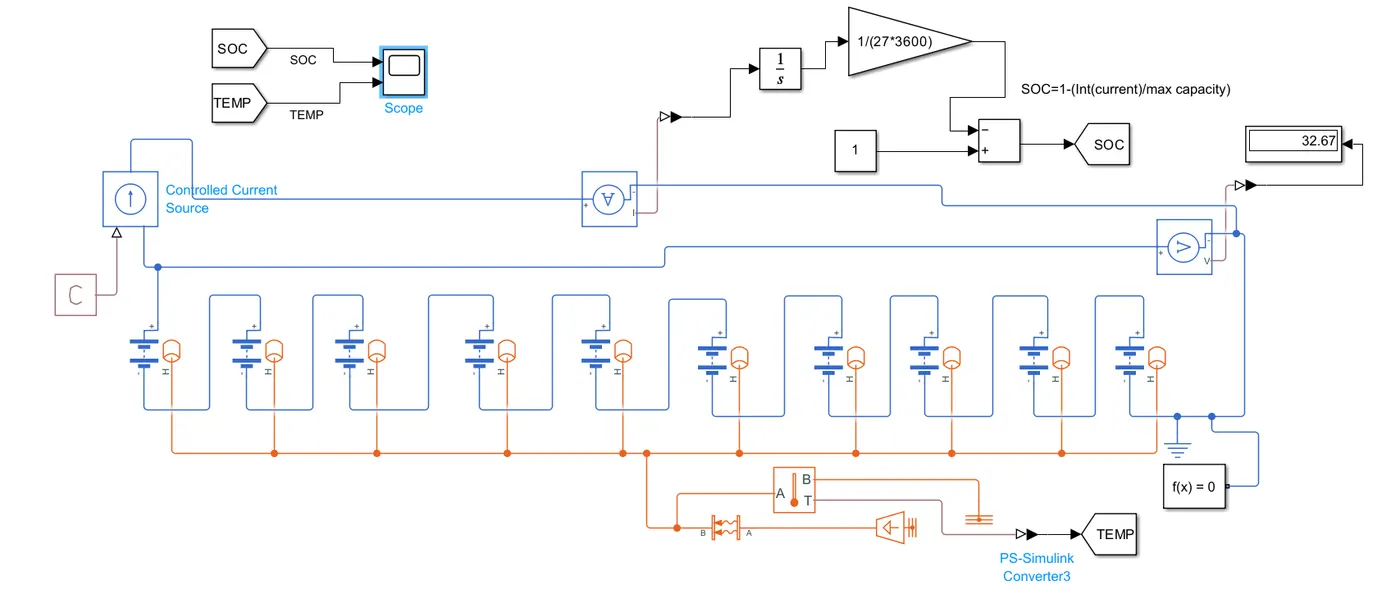
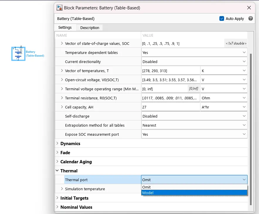
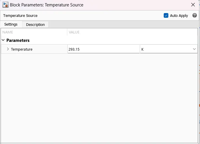
Here we have connected 10cells in series and battery parameters are set as shown below and in order to map the thermal parameters we need to manually change the Thermal port parameter to ->Model (we will get thermal port to map thermal behavior, (orange color)). The battery has an initial soc of 100% and then it is fully discharged in 1 hour/ 3600sec. The temp source is set as 293.15K.
SOC Estimation
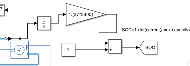
Coulomb counting is a common method used to estimate the state of charge (SOC) of a battery. It involves measuring the current entering or leaving the battery over time and integrating these measurements to estimate the SOC
SOC = 1- (Integrated Current / Battery Capacity)
the above equation is implemented in simulink model as shown below
Battery Pack heat trasfer area calculation
Let us suppose we are using cylindrical 18650 cells and we are provinding cooling to the top and bottom part.
1) Top and bottom area
Diameter of the battery= 18mm
The cells will be having a area of 18*10*18= 3240mm2* 2 (sides) =0.00648m2.
2) side area
Length of battery= 65mm
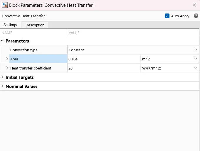
Area= length*breadth= 65*18*10=52000mm2* 2(sides)=104000mm2=0.104m2
CASE 1: Fixing the temperature and change the area for 3 values
a) Top and bottom cooling (area=0.00648m2) with a temp of 293.15K
OUTPUT
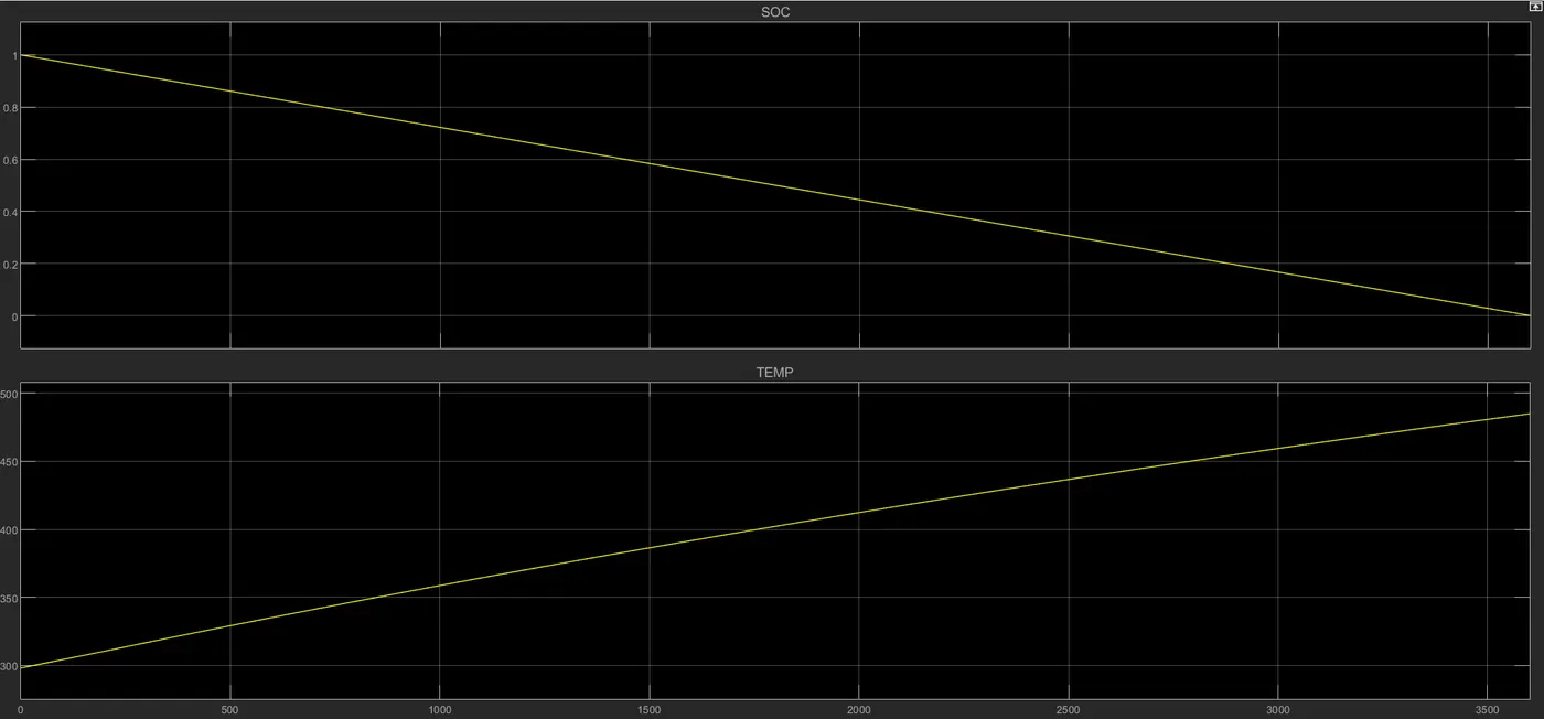
As we can see here after 3600 seconds the battery pack gets fully discharged and temp rises from 293.15K alll the way to 475K (201degC), this temperature is too high and the cooling provided is not at all sufficent, opreating the pack in this high temperature will lead to thermal runaway.
b) Side cooling (0.104m2) with a temp of 293.15K
OUTPUT
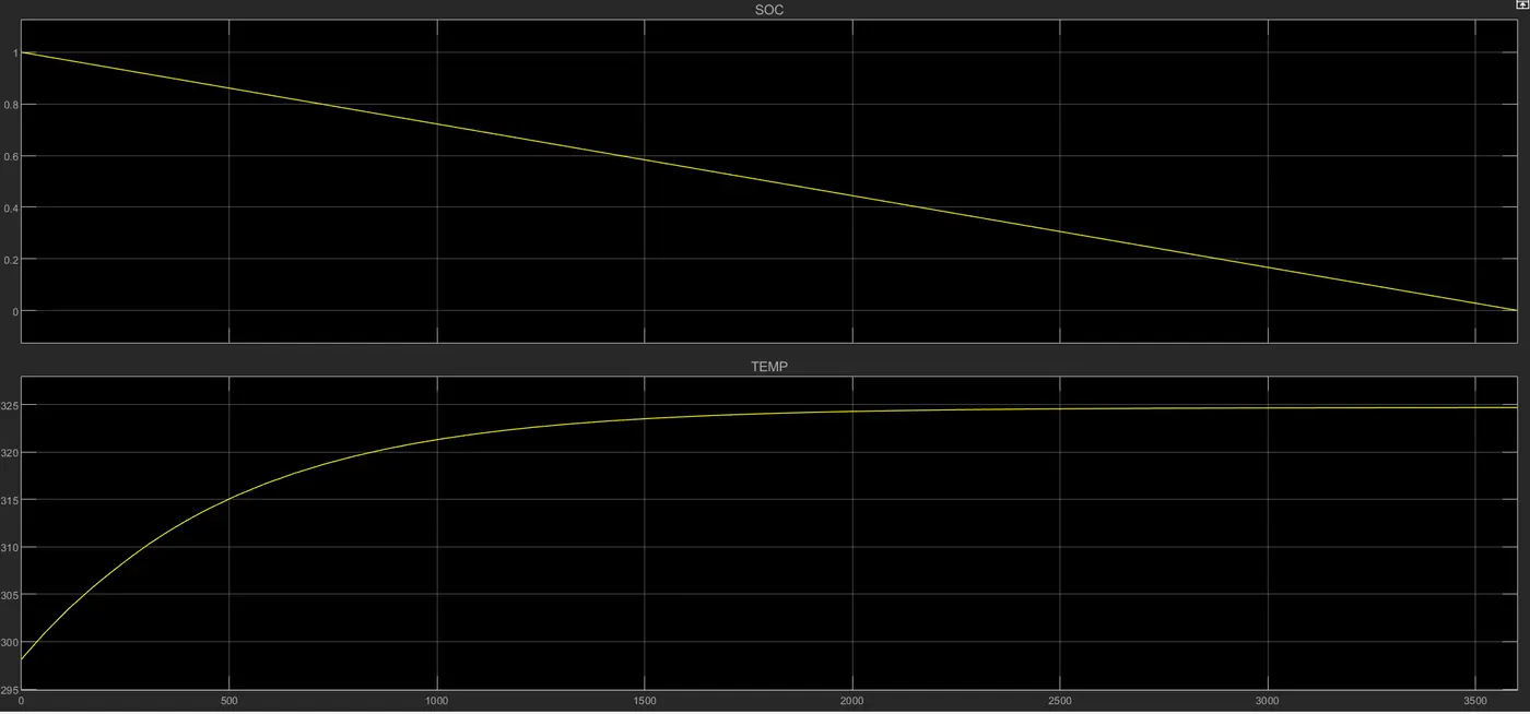
In this case we can see the temperature rise is not as high as the above case. At the end of one hour the temperature rises from 293.15K to 324K(51.8 degC) the temperature remains in the desired range and pack charging and discharging can be carried safely.
c) Top+side cooling (0.00648+0.104m2=0.11048m2) with a temp of 293.15K
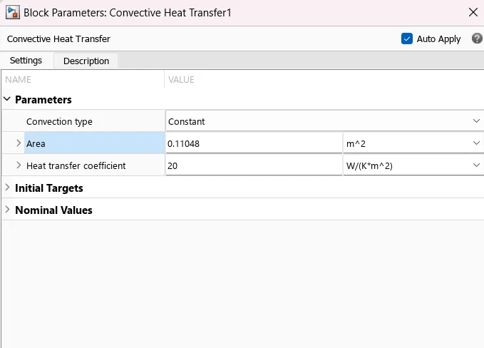
OUTPUT
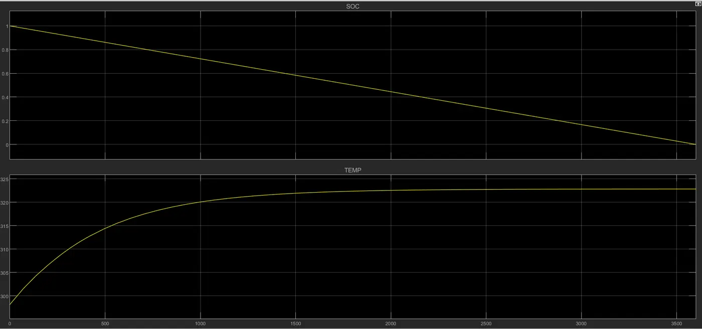
We can see that the thermal behavior is slightly better, we were able to maitain the temperature after discharge at 323K(49.8degC). A drop in temp of 2 degC compared to previous case.
Note: In real world scenarios we can proceed with case B as it still provides good thermals and also keeps the cost down by avoiding thermal management on top and bottom end of pack.
CASE 2: Fixing the area and change temperature for 3 values
a) Side cooling (0.104m2) with a temp of 293.15K
Already observed in case1, b)
b) Side cooling (0.104m2) with a reduced temp of 263.15K (-10degC)
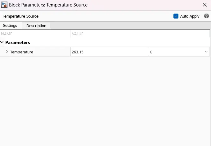
OUTPUT
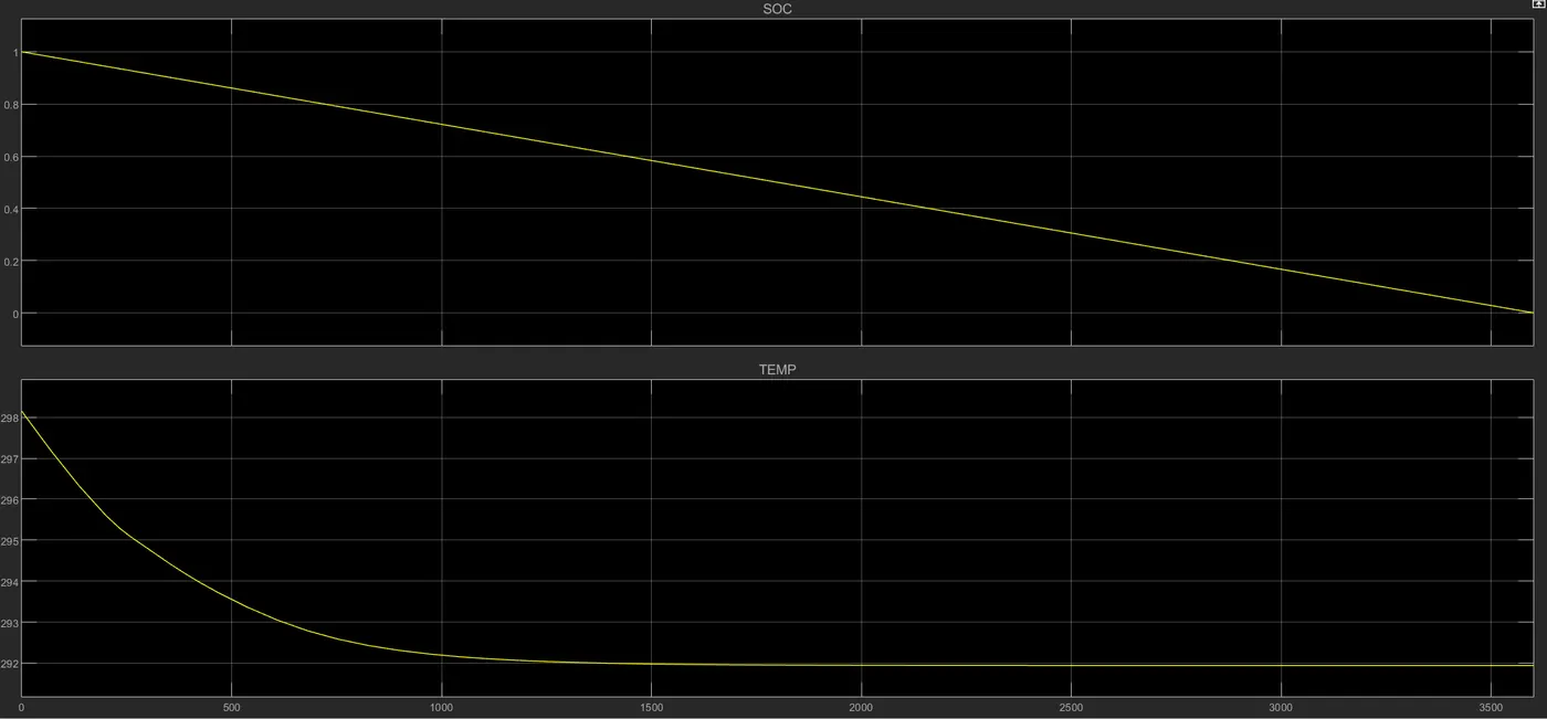
When the temperature was set to 263.15K (-10degC) we observe an abrupt behavior. This behavior we observing could be due to the fact that batteries function differently at low temperatures. When the temperature drops, the internal resistance of the battery increases and its capacity decreases. This could potentially cause the battery temperature to decrease further during discharge, especially if the current drawn is low.
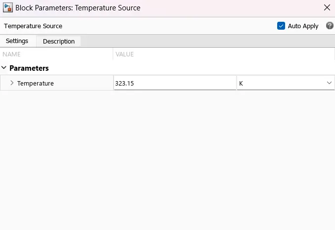
C) Side cooling (0.104m2) with a increased temp of 323.15K (50degC)
OUTPUT
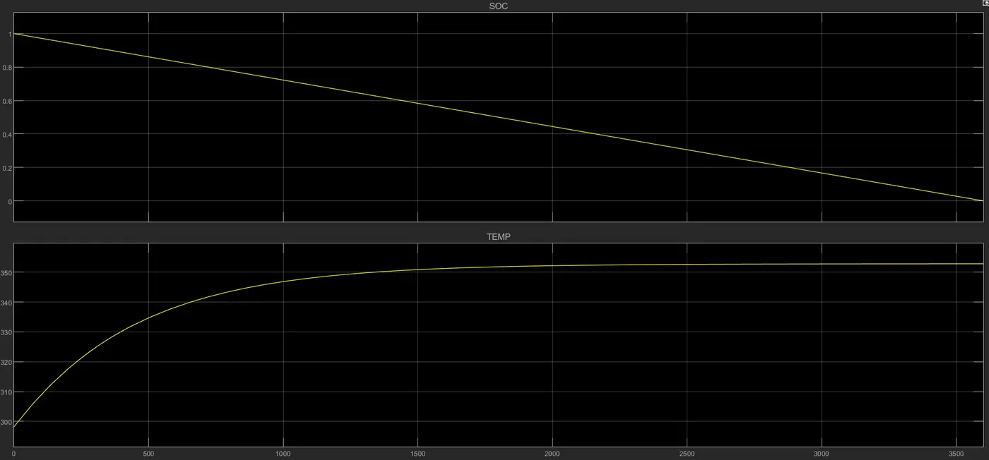
We can see that we have increased the temperature to 323.15K (50degC) still the the thermal managment was able to maintain the temperature of the battery pack at 352K (78.8 ddegC), therefore our thermal system can maintain the pack at operatable temperature even at higher source temperature