Project 2 Thermal modeling of battery pack
Aim: Using MATLAB for a 10-cell series lithium-ion battery model, simulate the thermal effects and compare life cycle performance at various temperatures, charge & discharge rates.
Theory:
A thermal management system keeps batteries operating safely and efficiently by regulating their temperature. High battery temperatures can accelerate battery ageing and pose safety risks, whereas low temperatures can lead to decreased battery capacity and weaker charging/discharging performance.
A battery thermal management system controls the operating temperature of the battery by either dissipating heat when it is too hot or providing heat when it is too cold. Engineers use active, passive, or hybrid heat transfer solutions to modulate battery temperature in these systems. Active solutions typically have a fan or pump pushing working fluid - such as air, water, or other liquid - to reduce or increase battery temperature. In a passive solution, heat sinks or pipes with thermally conductive materials transfer heat away from the battery. A hybrid solution combines key design features of both active and passive solutions.
Creating battery thermal software models that simulate the heat transfer process can help engineers analyze trade-offs in design parameters, evaluate performance, and implement control algorithms. Engineers can use MATLAB® and Simulink® to design battery thermal management systems that ensure a battery pack delivers optimal performance safely in various operating conditions.
SOC Estimation by Coulomb Counting
SoC Estimation by Coulomb Counting is based on the measurement of the current and integration of that current over time.
A battery cell's State of Charge (SoC) must maintain its safe operation and lifetime during charge, discharge and storage. However, SoC cannot be measured directly and is estimated from other measurements and known parameters. This leads to errors in the estimated SoC, which means it is impossible to exploit the full capability of the cell.
Coulomb counting gives a relative change in SoC and not an absolute SoC. If you measure the current over a given time, you have a measure of the number of Ah that have left or been received by the battery.
where:
SoC(t) = Estimated State of Charge at time, t
SoC(t-1) = Previous State of Charge at the time, t-1
I(t) = Charging or discharging current at time, t
Qn = Battery cell capacity
Δt = Time step between t-1 and t
If you want to know the absolute SoC, you need to know the starting SoC of the cell, SoC(t-1), as given in the equation. One option is to charge the cell to a known voltage fully. Charging to maximum cell voltage and SoC can be used as a reset and known point.
There are a number of sources of error with the coulomb counting method:
- Starting SoC accuracy
- Current measurement accuracy
- Current integration error
- Uncertainty in battery capacity
- Timing error
To define the accuracy you need, it is important that you first look at what the SoC is used for.
- The capacity of the cell that is remaining (fuel gauge on your phone or electric vehicle).
- An input to estimate the battery's available charge and discharge power capability.
- It is used in the calculation of the State of Health.
The accuracy required for these values will determine the accuracy required for the inputs to the SoC algorithm. This will impact the selection of the following:
- The components for cell voltage measurement.
- The voltage sense wires, connectors and connection locations.
- The current sensor or sensors.
- The voltage and current measurement channel accuracy.
- The timing circuit.
Simulink Model
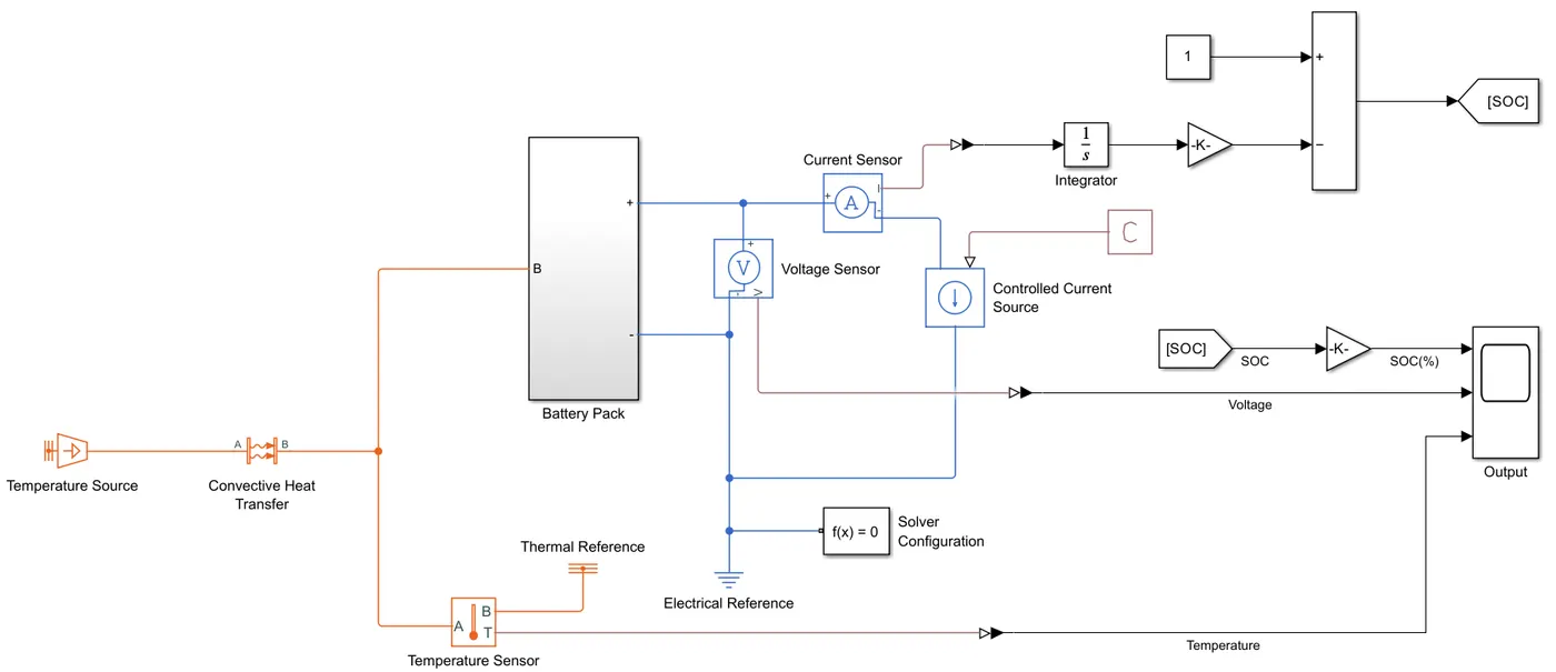
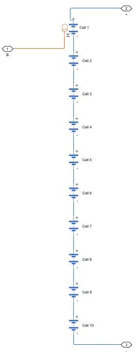
Battery Pack Subsystem
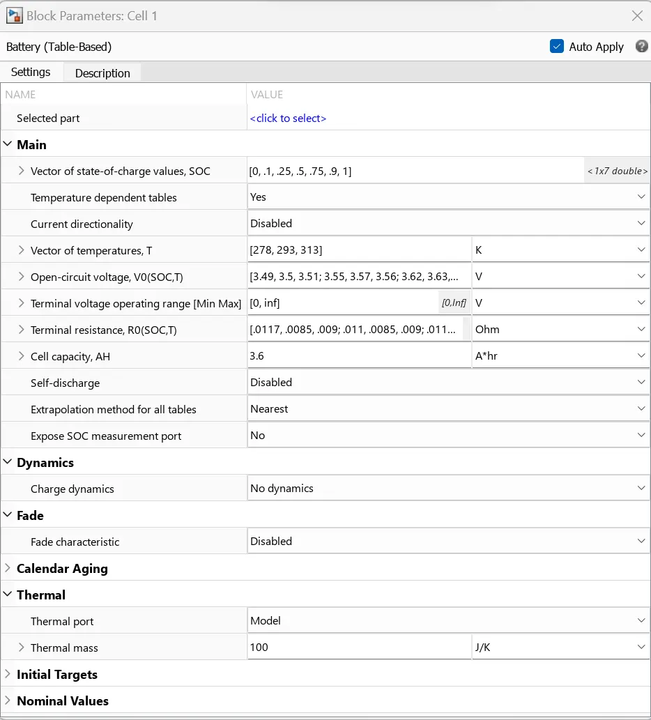
Battery (Table-Based)
This block models a battery based on tabulated characteristics such as state-of-charge, SOC, and optional temperature functions, T.
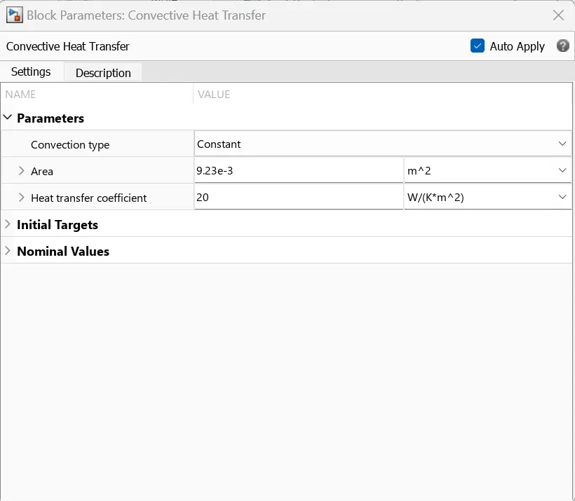
Convective Heat transfer (CHT)
This block models heat transfer in a thermal network by convection due to fluid motion. The heat transfer rate is proportional to the temperature difference, heat transfer coefficient, and surface area in contact with the fluid. The heat transfer coefficient can be either constant or variable. When the heat transfer coefficient is variable, specify it using the physical input signal at port K. If the heat transfer coefficient is variable, it remains at the Minimum heat transfer coefficient if the physical signal falls below this value.
Output:
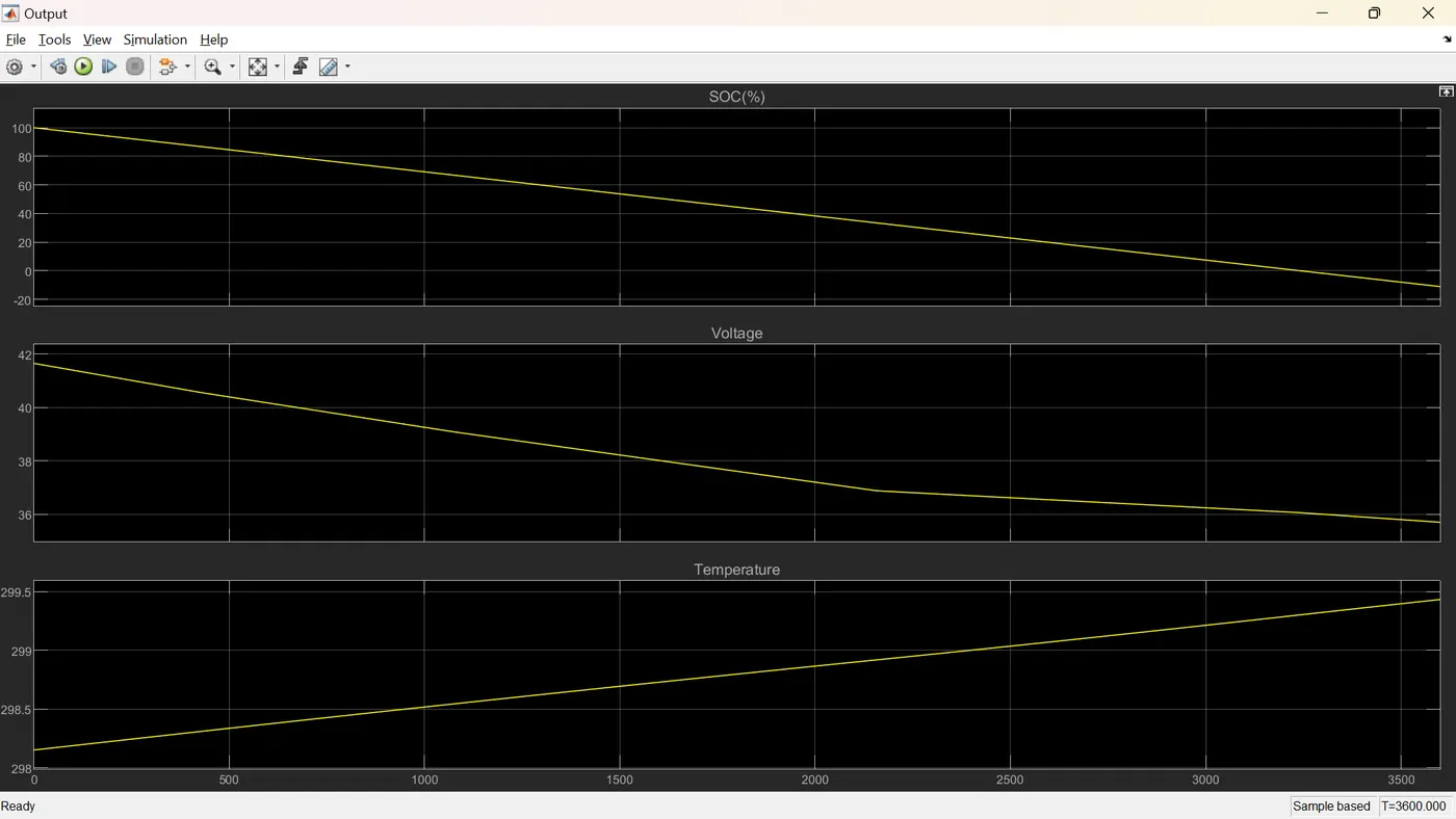
The model is simulated for 3600 seconds.
1. Considering T = 278 K
i. Area = 1e-4 m2
ii. Area = 1e-3 m2
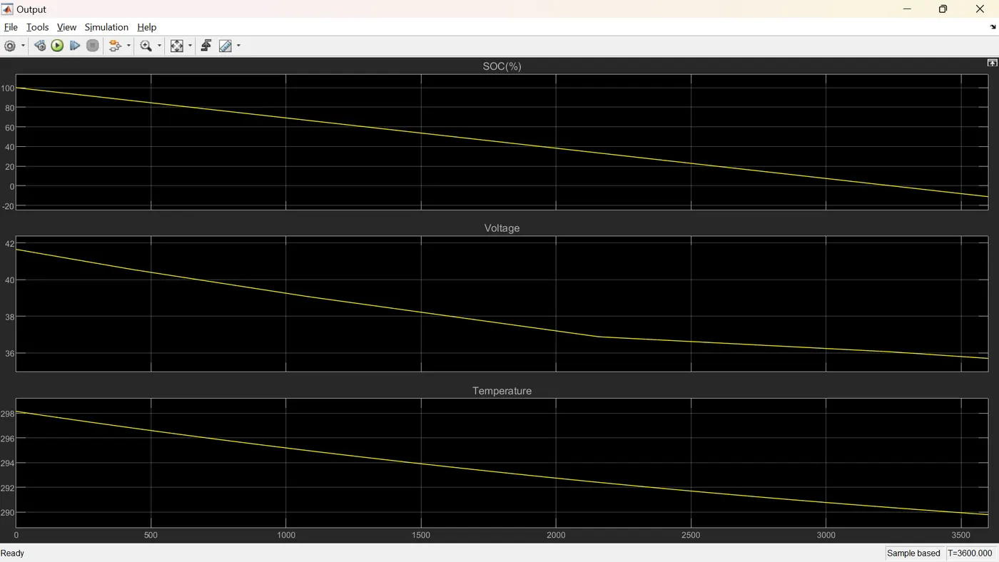
iii. Area = 1e-2 m2
2. Considering T = 293 K
i. Area = 1e-4 m2
ii. Area = 1e-3 m2
iii. Area = 1e-2 m2
3. Considering T = 313 K
i. Area = 1e-4 m2
ii. Area = 1e-3 m2
iii. Area = 1e-2 m2
Result:
From the scope, we can say that when the area increases, the temperature decreases faster. Hence, the battery pack should have more area.
Conclusion:
Hence, the thermal effects and compare life cycle performance at various temperatures, charge & discharge rates are simulated using MATLAB.