Project 2 Thermal modeling of battery pack
AIM:
For a 10 cell series lithium ion battery model, simulate the thermal effects and compare life cycle performance at various temperatures, charge & discharge rates using MATLAB.
In this project we will connect 10 Li-ion cells in series using MATLAB tools and then simulate the thermal effects and compare life cycle performance at various temperatures, charge & discharge rates.
Battery capacity (how many amp-hours it can hold) is reduced as temperature goes down, and increased as temperature goes up. This is why your car battery dies on a cold winter morning, even though it worked fine the previous afternoon. If your batteries spend part of the year shivering in the cold, the reduced capacity has to be taken into account when sizing the system batteries. The standard rating for batteries is at room temperature 25 degrees C (about 77 F). At approximately -22 degrees F (-30 C), battery Ah capacity drops to 50%. At freezing, capacity is reduced by 20%. Capacity is increased at higher temperatures – at 122 degrees F, battery capacity would be about 12% higher.
Battery charging voltage also changes with temperature. It will vary from about 2.74 volts per cell (16.4 volts) at -40 C to 2.3 volts per cell (13.8 volts) at 50 C. This is why you should have temperature compensation on your battery charger or charge control if your batteries are outside and/or subject to wide temperature variations.
WORKING OF MODEL:
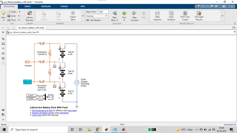
A lithium-ion battery pack of 10 cells is used. In order to check for the thermal effects, one of the cells is considered faulty. Fault in the sense that the temperature of this cell is higher than the other nine.
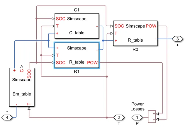
The battery is assumed to be air cooled and provided with ventilators with ambient air and temperature. For modelling this case, all the cells are connected with ambient temperature.
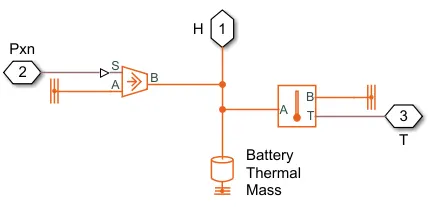
The convective heat transfer from surrounding to the cells and conductive between the cells is also modelled using the respective blocks.
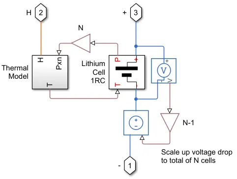
There are temperature sensor blocks used to detect the temperature from the cells. The current drawn from the cells is controlled by the 'Controlled Current Source' block.
The data of a drive cycle in the form of current is fed to this current controller.
A signal builder block is used to feed this drive cycle data and it is stored in the form of current vs time. After running the model, a SOC vs time and temperature vs time graphs are plotted.
The orange lines are the thermal connections connecting thermal blocks in the model. There is convection implementing block between the surrounding and the cells. A conduction block is also used to carry out the calculation of heat travelled between cells due to conduction. Ambient temperature source is used to cool the battery. Temperature measuring block is also used to sense the temperature of each cell in order to manage the heat in the battery by sending these measures to the BMS.
Blocks settings:
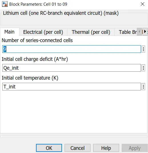
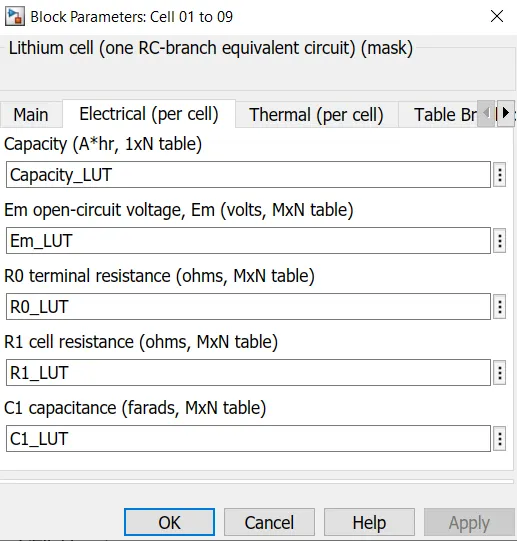
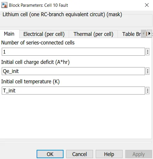
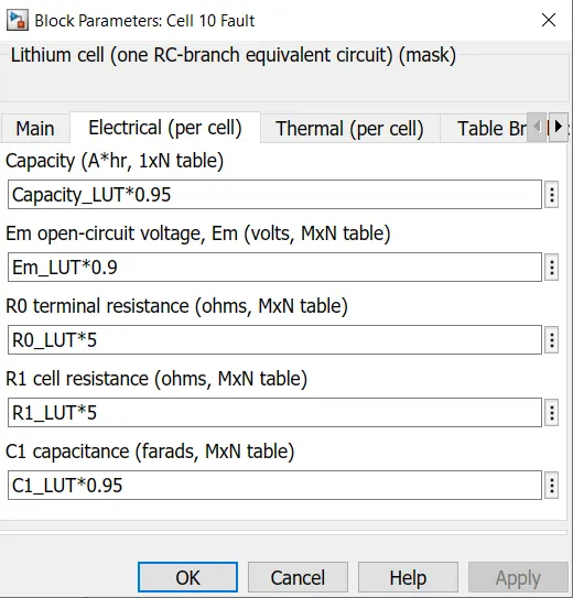
From the block parameters it is seen that the capacity, open circuit voltage and capacitance of cell 5 and 6 is reduced. Also, terminal resistance and internal resistance is increased.
The drive cycle data in the form of current vs time is shown below. A signal builder block is used to implement it in the model. This current data is sent to controlled current source block, so that it extracts the same amout of current through the battery pack.
Overall Model of the fault cell
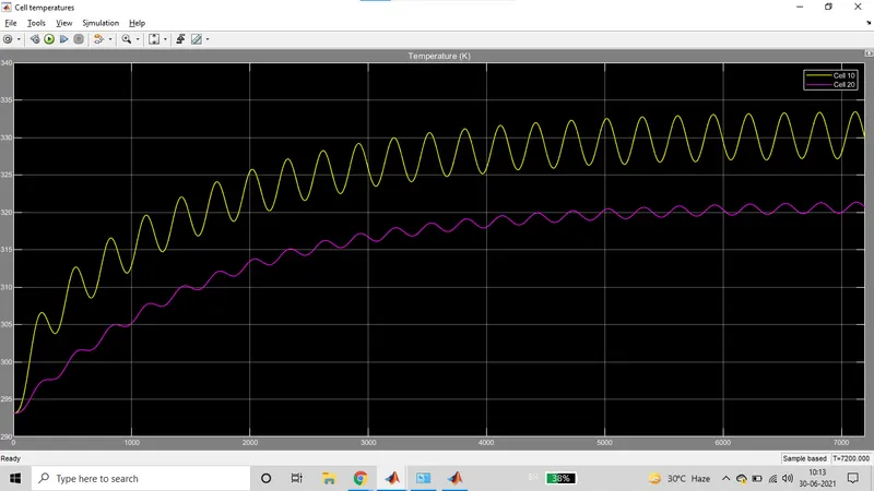
The aim was to see the change in the cell performance due to change in temperature. According to the model, there are ten cells in series from which 5th cell is faulty, meaning it has more temperature than others. The open circuit voltage and capacity is low, whereas the internal and terminal resistance is high. As seen in above plots these all factors have resulted in the following plot:
From the plot we get SOC and temperature of the cells w.r.t. time for a given drive data. It can be seen from the first plot of temperature that cell 5 has higher temperature than all other cells.
The initial temperature of all cells is 293.1 K. With ongoing driving condition for 22 minutes approximately, faulty cell temperature rises to 293.8K and other cells to 293.6K.
The rate of rise and fall in the temperature of the 5th cell is high which states that it is highly unstable. Higher temperature in any cell is not desired as it may increase the temperature on the surrounding cells.
The SOC of the fault cell is less than the other cells. Starting from 40% the fault cell reduced to 35% in 22 minutes. All other cells from 45% state of charge, came down to 40%.
This causes imbalance between cells and results in reduced life of the battery and deteriorates the performance.
The Lithium-ion batteries are widely used as energy sources in different hybrid systems, however, the operation characteristics of the battery in such systems are strongly dependent on the operation temperature and therefore, with purpose to improve these characteristics a good thermal control system should be utilized. This paper describes the modelling thermal management system for the battery pack in Hybrid Electric Vehicles (HEVs), which gives opportunity to control the operation temperature of the pack for different load cycles and ambient temperatures. The thermal model of the battery pack is created by using an equivalent electrical circuit with lumped parameters. The thermal control system is created as a combination of the cooling system of the internal combustion engine and the battery pack thermal control system. The heat transfer between these systems is performed by a plate heat exchanger where the inlet flow is controlled by a three-way valve with an electric actuator. Artificial intelligent algorithms together with estimator are applied in control system, with purpose to obtain suitable control properties.
Hence a model for 10 lithium ion cells in series was created and simulated successfully. The change in temperature of a single cell reduces the performance of the battery. Variation in the OCV also reduces the current drawing capacity and the temperature increases. The other main reason of the rise in temperature is the increased resistance, internal as well as terminal. Hence, thermal effects are simulated on a 10 cell series lithium ion battery.