Project 2 Thermal modeling of battery pack
AIM
Utilizing MATLAB, simulate the thermal impacts and evaluate life cycle performance at various temperatures, charge & discharge rates for a 10 cell series lithium ion battery model.
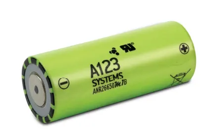
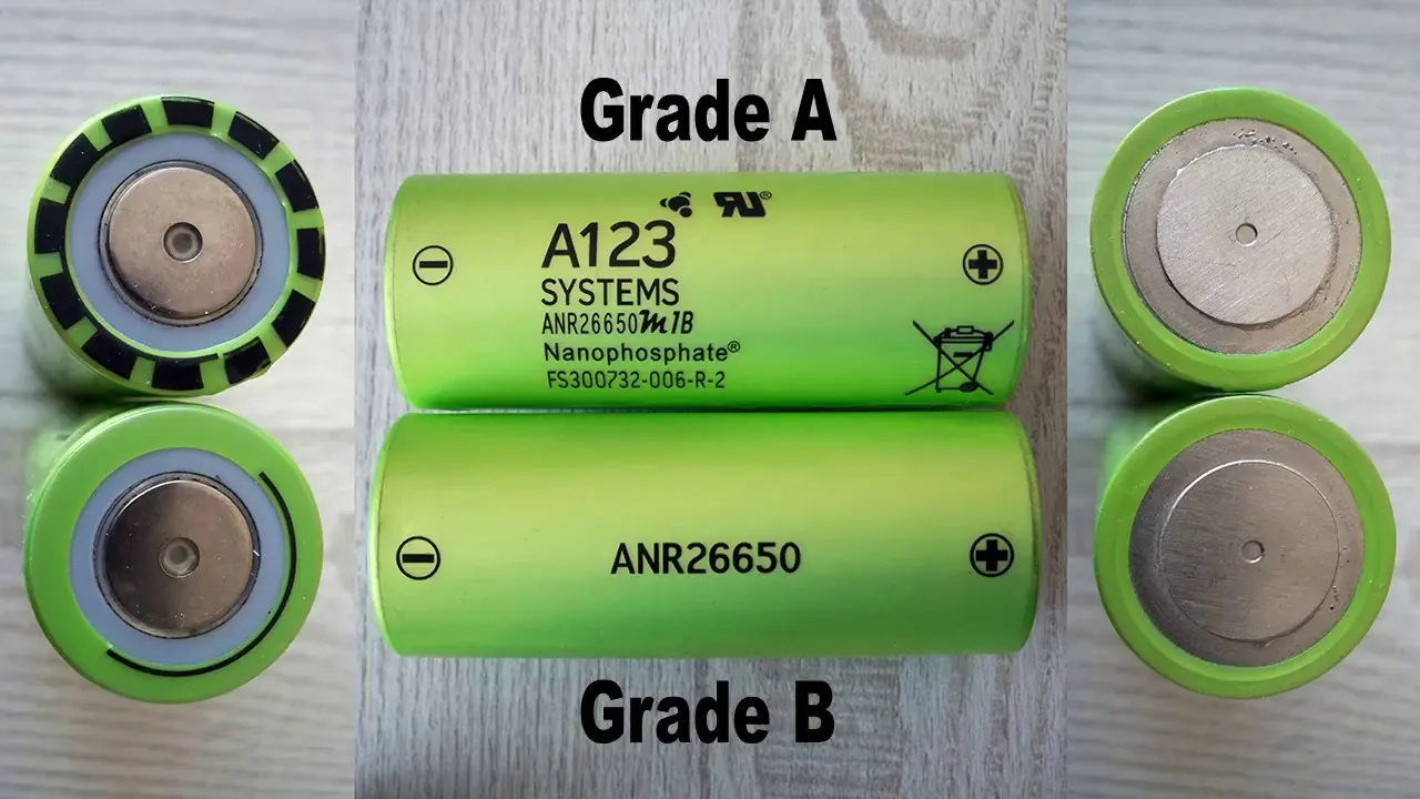
NANOPHOSPHATE LITHIUM IRON PHOSPHATE (LIFEPO4) ANR26650M1-BATTERY TECHNOLOGY
The high-performance Nanophosphate lithium iron phosphate (LiFePO4) battery technology used in the A123 Nanophosphate High Power LithiumIon Cell ANR26650M1-B delivers high power and energy density along with excellent safety performance and extensive life cycling in a lighter weight, more compact package. Our cells' low capacity loss and impedance development over time, along with their high useable energy throughout a wide state of charge (SOC) range, enable our systems to satisfy end-of-life power and energy demands with a minimum amount of pack oversizing.
APPLICATIONS FOR NANOPHOSPHATE LITHIUM IRON PHOSPHATE (LIFEPO4) ANR26650M1 BATTERY TECHNOLOGY
BUSINESS SOLUTIONS
- Datacentre advanced lead acid replacement batteries Telecom UPS backup
- IT backup
- autonomously steered automobiles (AGVs)
- Equipment for material handling and industrial robots
OFFICIAL SOLUTIONS
- military equipment
- military power networks
- Soldier strength
- focused power
SOLUTIONS FOR GRID
- frequency control
- integrating renewable energy
- reserves available
- distribution and transmission
COMMUNICATION SOLUTIONS
- Battery systems for hybrid, plug-in hybrid, and electric cars for:
- Off-road automobiles
- passenger cars
ANR26650M1-B TECHNICAL DATA
|
DIMENSIONS |
26 x 65mm |
|
WEIGHT |
76g |
|
POWER |
>2,600 W/kg and 5,800 W/L |
|
CAPACITY |
2.5Ah (nominal) / 2.3Ah (minimum) |
|
VOLTAGE |
3.3V (nominal) |
|
INTERNAL IMPEDANCE |
6 (1kHz AC typical, mΩ) |
|
RECOMMENDED STANDARD CHARGE METHOD |
2.5V to 3.6V CCCV, 60 min |
|
RECOMMENDED FAST CHARGE CURRENT TO 80% SOC |
4C to 3.6V CC, 12 min |
|
MAX. CONTINUOUS DISCHARGE
|
50A. |
|
MAX PULSE DISCHARGE |
120A (10 seconds) |
|
RECOMMENDED FAST CHARGE CURRENT TO 80% SOC
|
4C to 3.6V CC, 12 min |
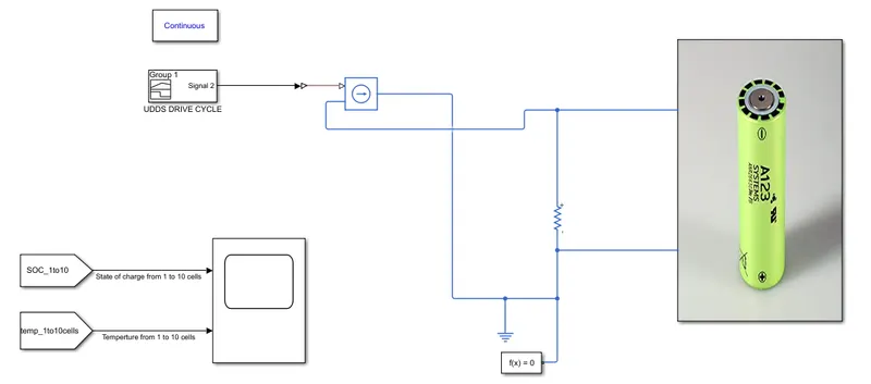
SIMULINK MODEL
PROCEDURE
STEP - 1
Add Powergui Block
One of the following approaches to resolving your circuit is available to you using the powergui block:
- Continuous, which employs Simulink's variable-step solver
- Discretization of the electrical system for a solution at certain time steps
- Solution to the phasor, continuous or discrete
STEP - 2
Select the Drive Cycle
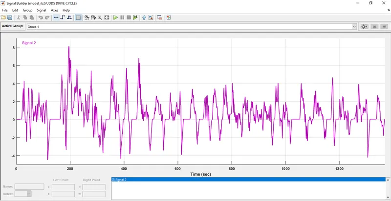
UDDS DRIVE CYCLE
In the provided xlc file, choose the Signal builder block and modify the time range to be from 0 to 1369. The Y values should be the UDDS Drive value.
https://docs.google.com/spreadsheets/d/1hN3pJfuIdn4psSIpPWlXtqRgpYs2EcjJ/edit#gid=1816926825
Step - 3
Add Controlled Current Source
Controlled Current Source
The Controlled Current Source block converts the Simulink input signal into an equivalent current source. The generated current is driven by the input signal of the block. The positive current direction is as shown by the arrow in the block icon.
STEP - 4
Signal from Controlled Current Source is connected to 10 ANR26650M1-B cells in Series Connection (10S)
10 ANR26650M1-B cells
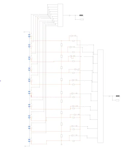
There is no heat movement via the temperature sensor when all 10 cells are linked in series. The thermal mass is the rate of temperature increase that is inversely related to the mass and specific heat of the material and proportionate to the rate of heat input into the substance. Electrical reference and solver setup are linked.
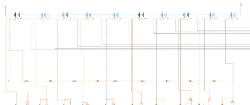
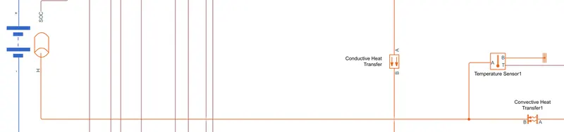
Convective and conductive heat transfer are linked in series from all of the ANR26650M1-B table-based cells, and temperature sensors are also installed to control the values.
Conductive Heat Transfer
If there is a temperature gradient in a solid or immobile fluid media, conduction as heat transfer occurs. When two nearby molecules meet, conduction occurs, where energy is transferred from the more energetic to the less energetic molecules. Heat moves in the direction of falling temperatures since molecular energy increases with temperature.
Convective Heat Transfer
The transmission of heat through currents of moving gas or fluid, known as convection, between two substances. As warm air or water rises and is replaced by a cooler parcel of air or water, free convection causes air or water to flow away from the heated body.
STEP - 5
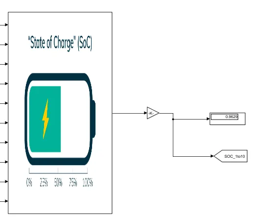
Estimate the SOC.
The overall state of charge for the 10 ANR26650M1-B cells connected in the Gain block is 0.9629.
STEP - 6
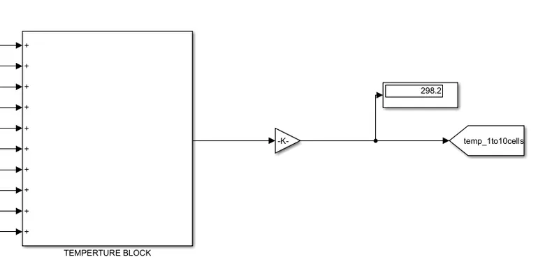
Estimate the Temperture.
All 10 ANR26650M1-B cells' temperatures are coupled in a gain block, and their combined value is 298.2.
Solver Configuration

- Each physical network represented by a connected Simscape block diagram requires solver settings information for simulation.
- The Solver Configuration block specifies the solver parameters that your model needs before you can begin simulation.
- Each topologically distinct Simscape block diagram requires exactly one Solver Configuration block to be connected to it.
RESULTS
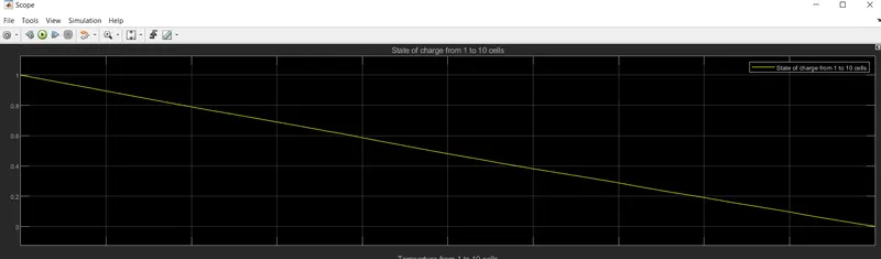
State of charge
- The quantity of energy in a battery at a given moment is measured as a percentage and is known as the state of charge (SOC).
- The graph below shows how the energy output of 10 ANR26650M1-B cells started to decline from 1 to 0.1.
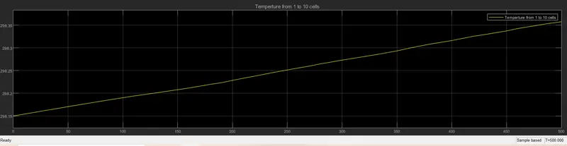
Temperature
The 10 ANR26650M1-B cells' temperatures are gradually raised from 298.2 to 298.35.
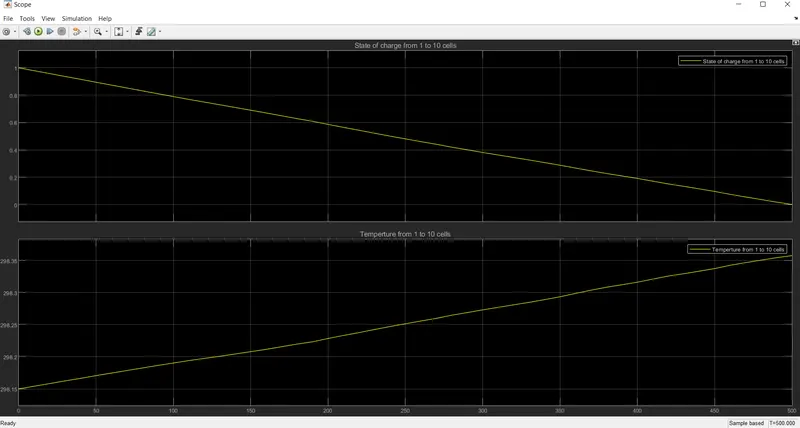
SOC and Temperature
CONCLUSION
The thermal impacts and life cycle performance comparison at various temperatures as well as state of charge have been estimated for the ANR26650M1-B 10 cells series in lithium ion battery model using MATLAB. Finally, as seen in the result, the temperature is steadily rising from 298.15K and the Soc is starting to decline from 1.