Project 2
CONSTRUCTION OF A P1 HYBRID VEHICLE AHEAD ENERGY-BASED FUEL CONSUMPTION MODEL
OBJECTIVE
The main objective of this project is to model a P1 hybrid and to comprehend how it works. For this project, the Honda Insight motor and battery are taken into consideration, and data is then obtained from the ADVISOR data source created by NREL, USA. In the project files, there are data.
AIM
This project's goal is to measure the hybrid car's increased fuel efficiency on the urban cycle (UDDS) and highway cycle as compared to a conventional vehicle (HWFET). Additionally, to analyse and comprehend the vehicle's working parameters, such as battery voltage, current, SOC, engine and motor speed, torque, and transmission speed.
HYBRID ELECTRIC VEHICLE (HEV) P1
A complete HEV model, including an internal combustion engine, gearbox, battery, motor, and related powertrain management algorithms, is represented by the hybrid electric vehicle (HEV) P1 reference application. Use the reference application to evaluate a HEV P1 hybrid's hardware-in-the-loop (HIL), analyse trade-offs, and optimise control parameters.
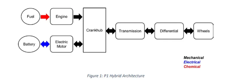
Crankshaft mounted electric machine (P1)
Honda chose the P1 design for their first-generation Integrated Motor Assist (IMA) technology because it allows the electric motor to be linked directly to the crankshaft. The electric motor serves as a generator, an engine starter, a motor (to help the engine), and a generator during vehicle braking.
The fact that the electric motor can produce more torque than the BiSG because there is no belt restriction is one of the solution's biggest benefits. The torque demands on the electric motor, however, can be quite high because there is no speed to torque ratio between the electric machine and crankshaft. Two examples of P1 MHEV architectures are:
- Honda Insight Hybrid 2009 (with Integrated Motor Assist technology)
- Mercedes Benz S400 Blue hybrid 2010
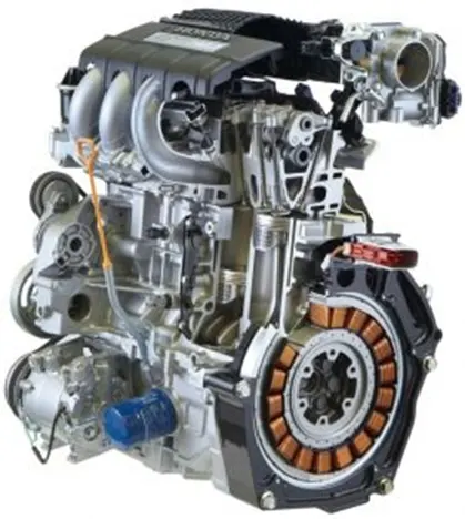
For example, the main characteristics of the crankshaft-mounted electric machine for mild hybrid Honda Insight 2009 are summarized in the table below.
HONDA INSIGHT MOTOR AND BATTERY

|
Electric machine performance |
Maximum torque (at crankshaft): up to 34 Nm |
|
Hybrid modes(functions) |
Idle Stop & Start |
|
Advantages |
Higher efficiency |
|
Disadvantages |
Output torque limited by the size of the electric machine |
|
Overall characteristics |
Torque Boosting Capability: High (if electric machine is capable) |
The elimination of the belt drive is the main benefit of a P1 mild hybrid design over a P0. As a result, the efficiency somewhat improves (there are no longer any belt losses), and the amplitude and reaction of the electric machine torque may be increased (no more belt slip).The functions (modes) performed by this mild hybrid topology are similar with those of a BiSG (P0), but, overall, P1 variants are significantly more expensive and have a greater negative influence on the current vehicle design. Therefore, the development of crankshaft-mounted integrated starter generator solutions for MHEV applications is not being funded by car manufacturers or system suppliers. The electric machines are on the engine side in both the P0 and P1 mild hybrid versions, eliminating any chance of mechanical detachment. Because of the torque losses, torque boosting, and energy recovery are not particularly effective. Furthermore, it is impossible to recover electrical energy while coasting with the engine off.
SIMULINK MODEL
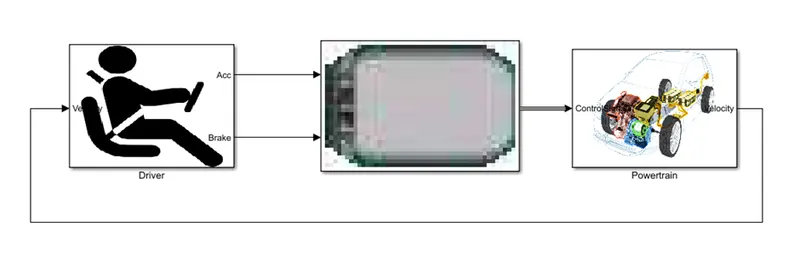
Driver Model
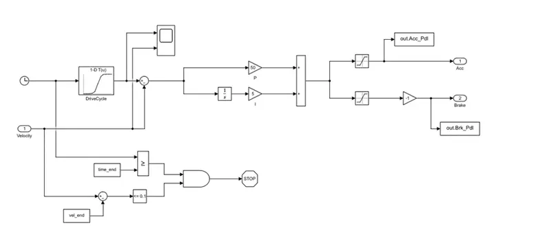
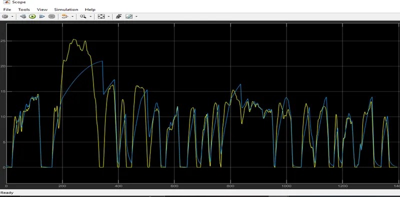
Based on the desired condition and the existing state of the vehicle, the driver model creates the command for the accelerator and brake pedals. There are several models with varying degrees of authenticity, whether they are used to simulate autonomous systems or human behaviour. In this study, the driver is easily simulated by a PI controller, which provides the control signal and adjusts the block's settings to produce the intended outcomes depending on the discrepancy between the desired and actual (feedback) speed profiles. Additionally, a feedforward model with customised brake and accelerator instructions is used to mimic the vehicle's acceleration test from zero to sixty miles per hour.
CONTROLLER
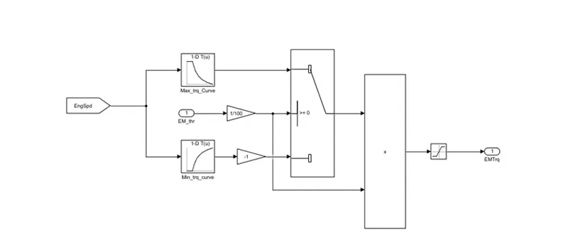
The way an electric motor functions is managed by gadgets referred to as controllers. In artificial lift applications, motor controllers are frequently used in conjunction with switchboards or VFDs to control the operation of the main mover. Controllers often contain a manual or automatic way for starting and stopping the motor, selecting forward or backward rotation, accelerating or decelerating, and regulating other operational parameters. Motor controllers can also provide security for the artificial lift system by regulating or limiting torque and protecting against overloads and issues. In addition to application-specific control logic, many controllers offer additional features like data logging and collection.
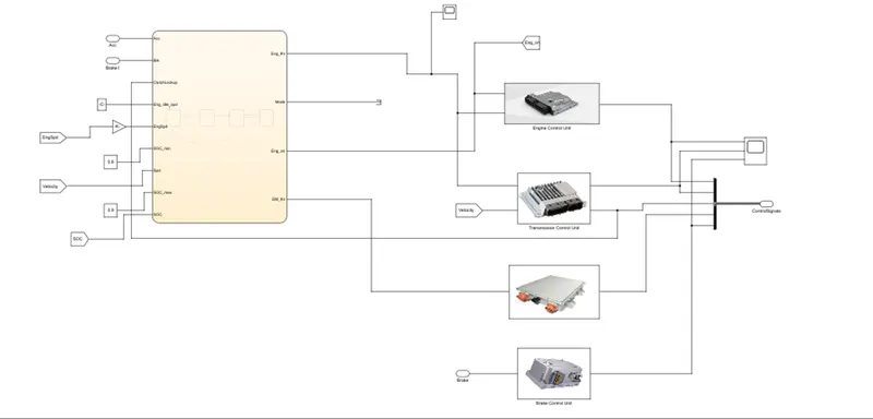
ENGINE CONTROL UNIT
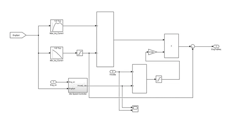
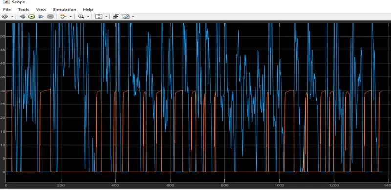
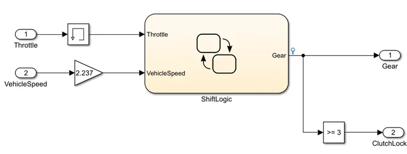
TRANSMISSION CONTROLS SIGNALS
ELECTRIC MOTOR CONTROLLER
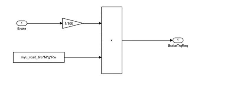
BRAKE CONTROL UNIT
POWERTRAIN
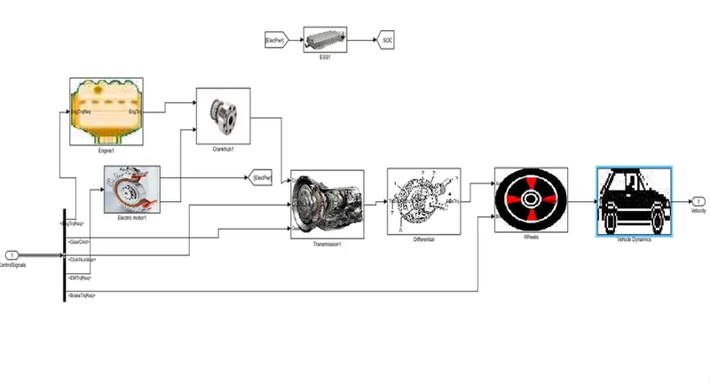
The powertrain refers to the entire system of components that moves your automobile forward. Your car's engine produces power, which the powertrain subsequently distributes to the wheels on the road. A powertrain's key components include the engine, gearbox, wheels, vehicle dynamics, and differential. Let's look at each one in turn
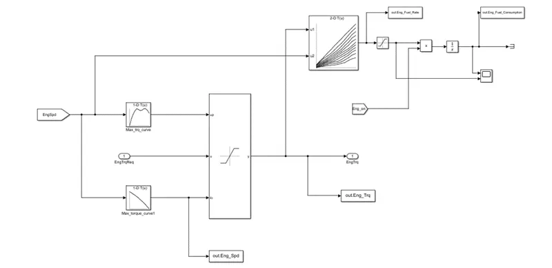
ENGINE: Your car's circulatory system consists of and the source of its power, the engine. A crankshaft, which transforms the oscillating action into a rotating motion, and pistons, which oscillate inside of cylinders, make up an engine.
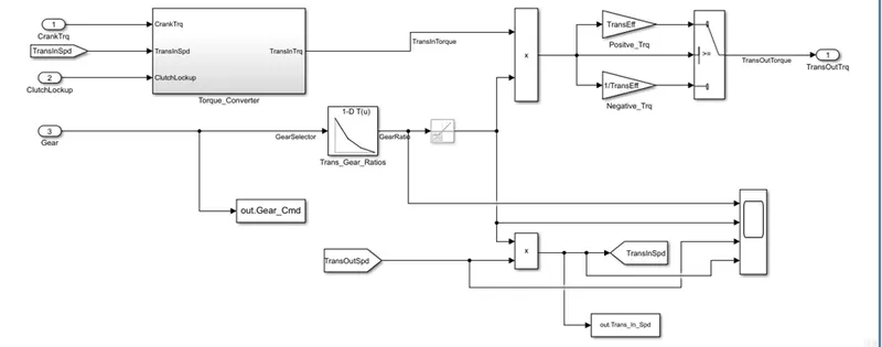
TRANSMISSION: A fundamental part of your automobile called the gearbox ensures that the right amount of power is sent to the wheels. Like a car's gearbox, the transmission transfers engine power to the wheels by adjusting it in response to road conditions.
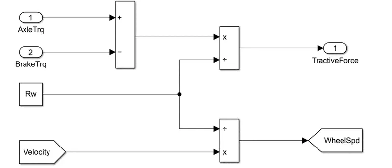
Wheels: A drive wheel is a wheel on a motor vehicle that transmits torque from the tyres to the road, which propels the vehicle, into tractive force. The powertrain's capacity to deliver enough torque to the wheel to overcome stationary forces causes the vehicle to move either forward or backward. A two-wheel drive vehicle only has two driven wheels, frequently both at the front or back, compared to a four-wheel drive vehicle's four driven wheels.
Differential: A differential is one part of the rear axle. It allows the back wheels to spin at different rates. When turning a corner, for example, the differential is essential because the outside wheel must turn more quickly than the inner wheel. Without a working engine, your automobile cannot move; therefore, it is crucial. In a nutshell, it is a group of parts that work together to create, transform, and use energy to move your car forward.

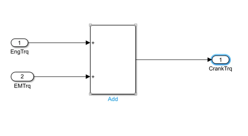
Crank Hub: The Crank Hub design enables the timing gear to spin independently from the crank, necessitating, at the very least, re-timing of the engine and, at worst, creating piston to valve contact that would damage the engine and necessitate a thorough engine overhaul.
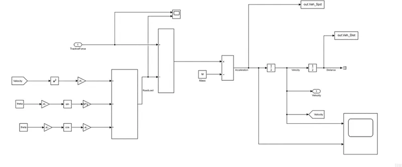
Vehicle Dynamics: Tire characteristics and vehicle dynamics are closely connected. The tyre slip angle is the angle between the direction of the tire's heading and the direction of travel.
ENERGY STORAGE SYSTEMS FOR ELECTRIC VEHICLES
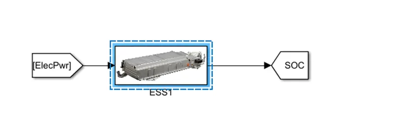
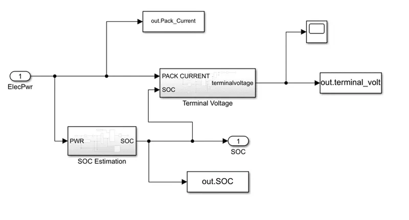
The manuscript Energy Storage Systems for Electric Vehicles examines lithium-ion (Li-ion) battery fast charging and the best fast charging strategy, route planning and exploration, automated guided vehicle energy consumption, range reliance on atmospheric conditions, energy management (using artificial intelligence techniques like recurrent neural networks), regenerative braking efficiency optimization, energy control strategies, and inductive wireless charging systems. Artificial neural networks, recursive estimators, model-based adaptive joint estimation of SoC and battery capacity, dual nonlinear Kalman filter, and fuzzy unscented Kalman filtering algorithms are also used to present state of charge (SoC) estimators for Li-ion cobalt battery hybrid electric vehicles (HEVs) or for electric vehicles (EVs), as well as state of health estimators.Li-Ni0.33Mn0.33Co0.33O2 (Li-NMC) batteries, polymer electrolyte membrane fuel cells, storage cells (such as Li-ion polymer batteries), and thermal storage employing metallic phase transition materials for heating are also included. Reynold's number turbulent- and coupled diffusion-induced stress battery models are also discussed, as well as Li-ion battery performance. In addition, active equalisation techniques for retired power Li-ion batteries for off-board renewable energy storage are covered, along with degradation and essential concerns for power battery reuse.
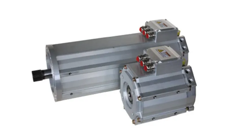
ELECTRIC MOTOR
Fundamentally, an electric motor (EM) is a rotating electromagnetic two-way energy conversion tool that may transform electrical energy into mechanical (motoring) or mechanical energy into electrical (generating). There are several techniques to accomplish this energy conversion, even though the fundamental concepts are the same in each case. EMs used in automobile traction applications include induction motors, permanent magnet synchronous machines (PMSM), switching reluctance, DC machines, etc. PMSM can't work at high speeds despite having a very high efficiency and power density. As a result, the constant power range is reduced. Induction motors are inexpensive, easy to design and build, reliable, and offer a wide speed range. However, they are less effective than PM motors, have a low power density, and have a significant heat issue when operating at high speeds. Switched reluctance motors are currently pricey yet have extremely high speeds. Tesla models and the now-discontinued Toyota Rav4 EV employ induction motors against the industry norm of using AC PMSM motors.
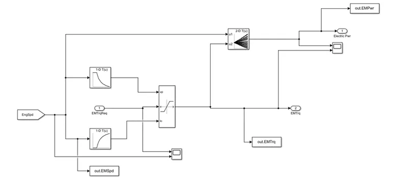
SIMULINKMODEL
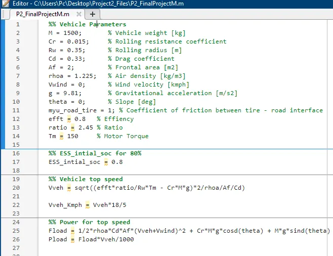
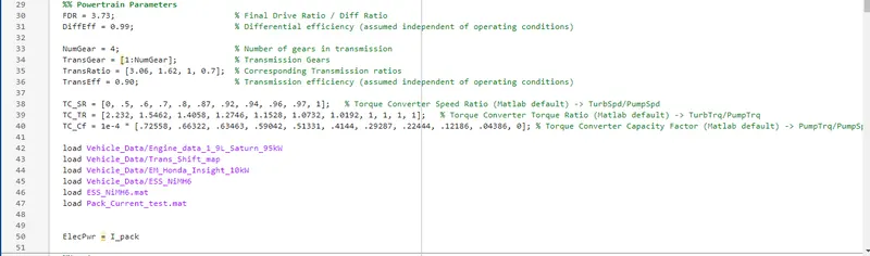
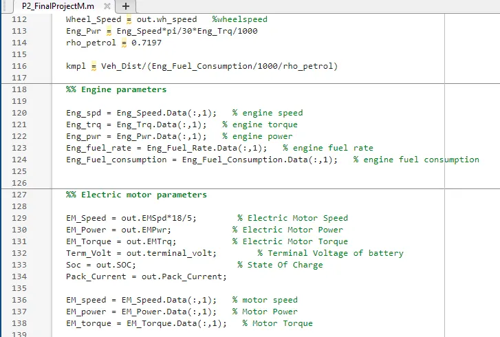
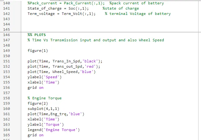
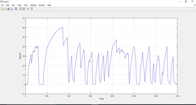
MATLABCODE:
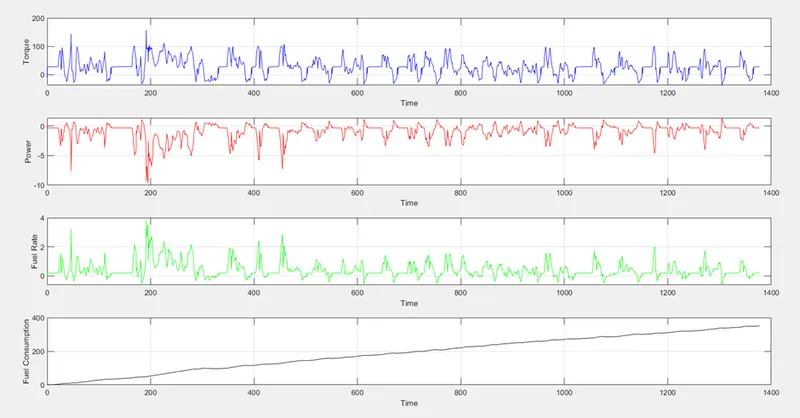
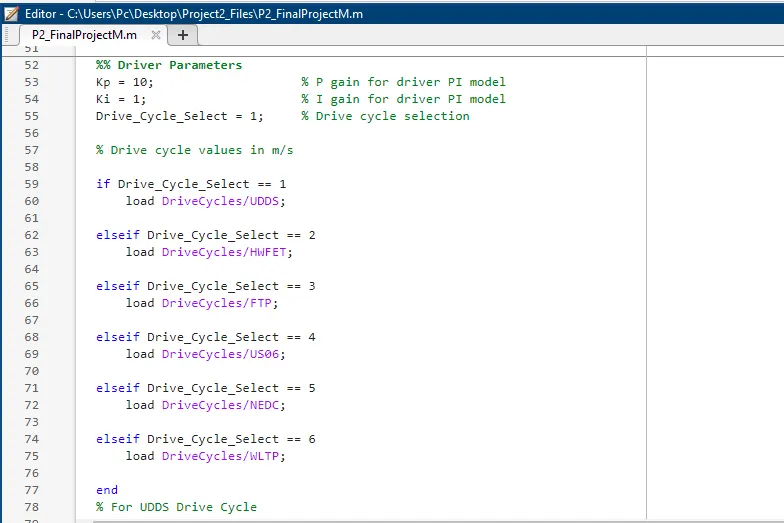
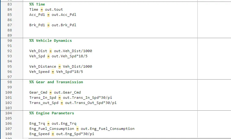
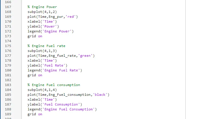
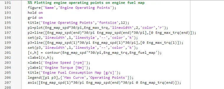
MATLAB CODE 2