Project 2 Thermal modeling of battery pack
THERMAL MODELLING OF BATTERY PACK
OBJECTIVE:
For a 10 cell series lithium ion battery model, simulate the thermal effects and compare life cycle performance at various temperatures, charge & discharge rates using MATLAB.
INTRODUCTION:
Lithium-ion batteries, with high energy density (up to 705 Wh/L) and power density (up to 10,000 W/L), exhibit high capacity and great working performance. As rechargeable batteries, lithium-ion batteries serve as power sources in various application systems. Temperature, as a critical factor, significantly impacts on the performance of lithium-ion batteries and also limits the application of lithium-ion batteries. Moreover, different temperature conditions result in different adverse effects. Accurate measurement of temperature inside lithium-ion batteries and understanding the temperature effects are important for the proper battery management.
In this project we are going to simulate the thermal effects of the lithium ion battery module for various temperatures and charge,discharge rates using the MATLAB.
LITHIUM ION BATTERY MODEL:
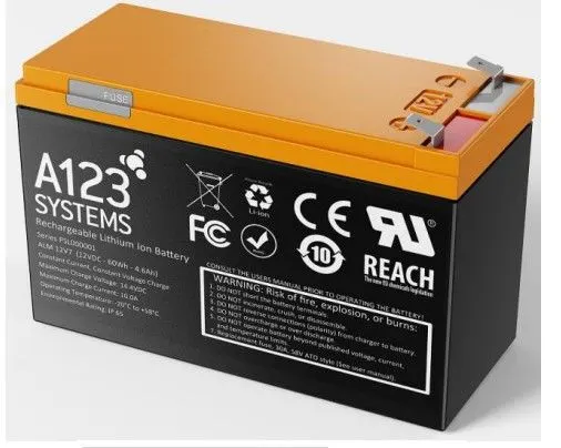
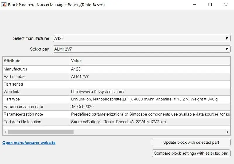
In this model we are using the lithium ion battery model ALM 12V7 which is the default battery module used in the table based battery model in Simulink.
A123 Systems lithium ion rechargeable ALM 12V7 battery is based on proven ANR26650 cells. The battery offers high power, long cycle and calendar life, and superior safety due to the use of patented Nanophosphate® technology. ALM 12V7 modules are drop-in replacements for 12V7 lead acid batteries with an integrated on-board cell balancing system that provides long battery life
SPECIFICATIONS:
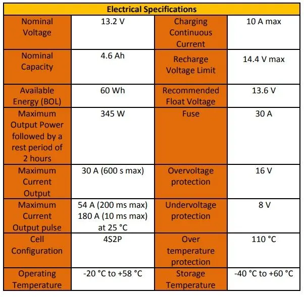
The below table shows the specifications of the battery used in this model
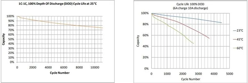
The below plots shows the discharge and cycle life characteristics of the battery model used:
DISCHARGE CHARACTERISTICS: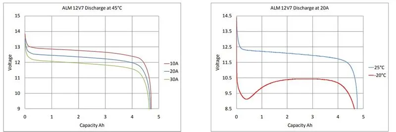
CYCLE LIFE PERFORMANCE:
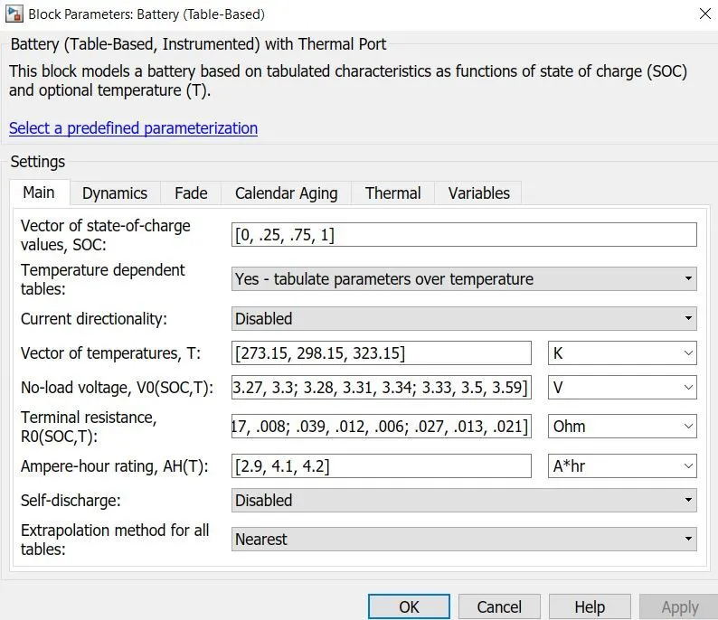
SIMULINK BATTERY MODEL PARAMETERS:
The below battery parameters are taken into consideration for the model
MODEL 1:
SIMULINK MODEL:
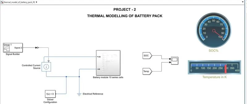
Explanation of main circuit:
- Battery module which consists of 10 batteries connected in series is created as a subsystem.
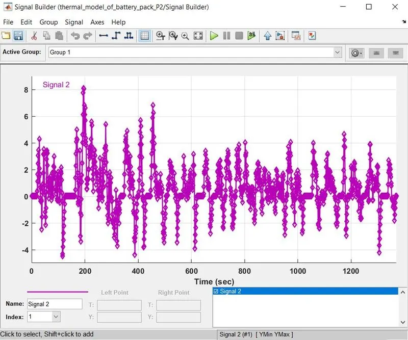
- Thermal modelling of a battery pack consist of signal builder block which consist the UDDS drive cycle current profile as input signal.
- controlled current source block is given to give the controlled drive cycle current to the battery model.
- The output is get from From block,the ouput here we need is SOC and Temperature of the battery pack.
- Dashboard is given for SOC% and Temperature of the battery pack.
- solver configuration and electrical reference is given.
- scope block is added to get the output.
Signal block:
SUB SYSTEM OF 10 SERIES BATTERY MODULE:
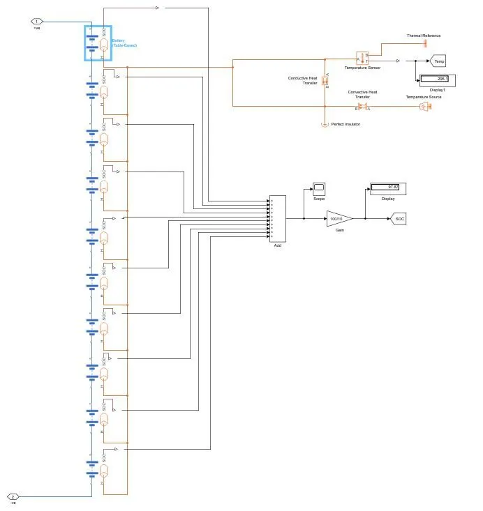
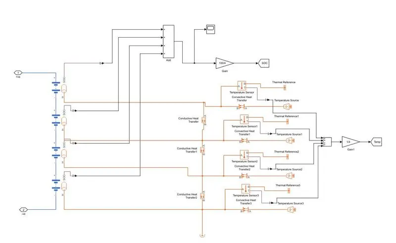
Explanation of sub system of battery module circuit:
The subsystem consist of the the 10 table based battery model connected in series, positive of one battery is connected to negative of another battery
The SOC and thermal port is activated by selected table based battery block>simscape model>block choice>Instrumented,show thermal port.
THERMAL PART:
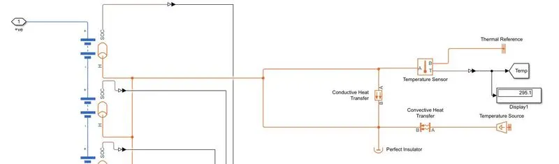
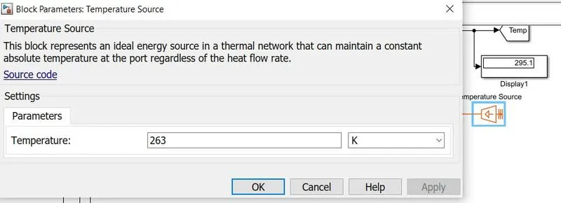
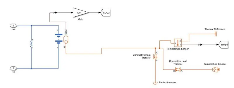
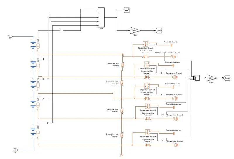
- The thermal part consist of Temperature source block which gives the temperature to the battery model.
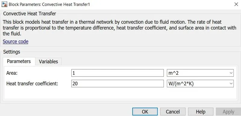
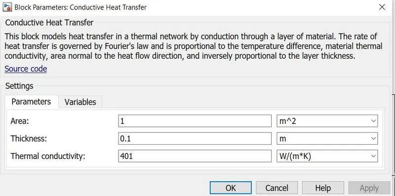
- The both conductive and convective heat transfer is take place between the battery and environment which is given by conductive and convective heat transfer blocks.
- The output temperture is sense by using the temperature sensor block.
- Thermal reference block is added.
- Same temperature and heat transfer is given to all the batteries.
- Perfect insulator block is added assume the insulator at the battery pack end.
Convective heat transfer:
Conductive heat transfer:
SOC MODEL PART:
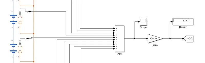
- All the output from the SOC is converted into simulink signal using PS-Simulink converter and added using ADD block.
- Gain block is added to get the SOC in percentage,Display block is connected and goto block is used to get the output.
SIMULATION OF THE BATTERY MODEL:
The simulation is run 1370 secs,because of udds signal have 1370 current profiles.
Here we run the simulation for 3 cases
Case 1: Temperature -10 deg(263 K)
Case 2: Temperature 25 deg(298 K)
Case 3: Temperature 45 deg(318 K)
For all the cases assume:
Conductive parameters:
Area: 1 m^2,Thermal conductivity: 401 W/(m*K),Thickness: 0.1m,
Convective parameters:
Area: 1 m^2,Heat transfer coefficient: 20 W/(m^2*K),
CASE 1:
Temperature for case 1( -10 degree celcius):
given temperature in temp source is 263 k
Plot for case 1:
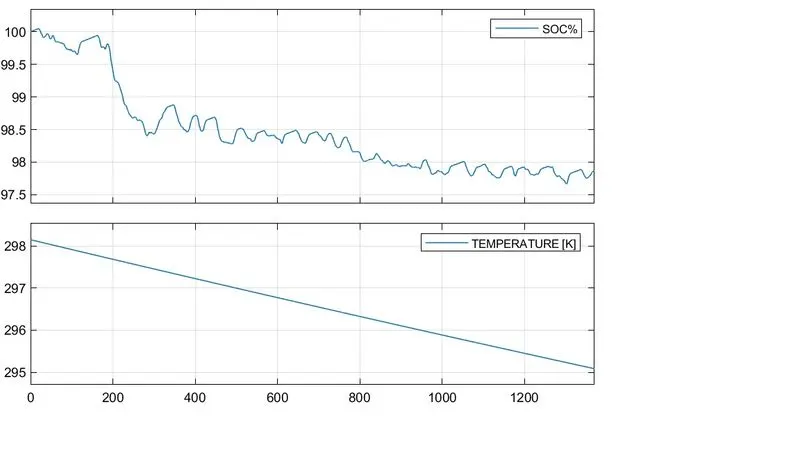
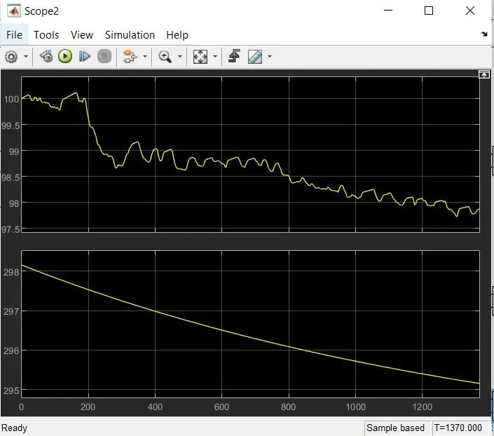
- The plot results shows the SOC of the battery module is decresed from 100% to 97% at the end of UDDS drive cycle.
- Initial temperature of the battery is 298K.
- The temperature of the battery module decrease from 298 K to 295 K.
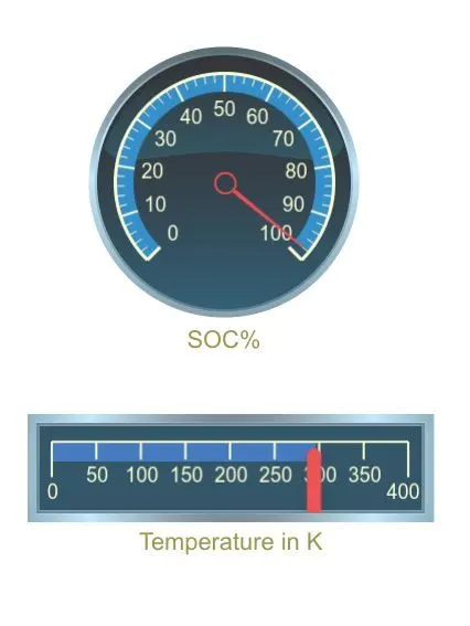
Dashboard result of case 1:
The dash board shows the final SOC % and temperature of the battery module at the end of drive cycle.
CASE 2:
Temperature for case 2 (25 degree celcius):
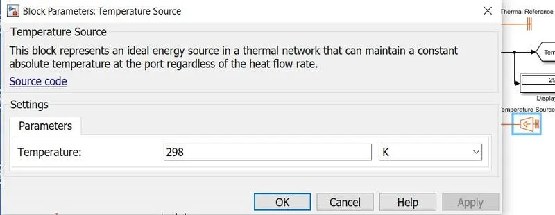
given temperature in temp source is 298 k
plot results for case 2:
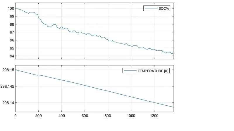
- The plot results shows the SOC of the battery module is decresed from 100% to 94% at the end of UDDS drive cycle.
- Initial temperature of the battery is 298K.
- The temperature of the battery module decrease from 298.15 K to 298.13 K.
- Here we see that the temperature is maintained at near to the ambient temperature.
Dashboard results of case 2:
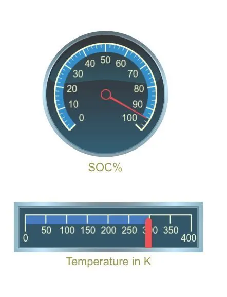
The dash board shows the final SOC % and temperature of the battery module at the end of drive cycle.
CASE 3:
Temperature for case 3 (45 degree celcius):
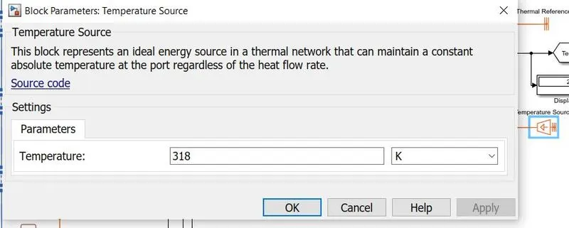
given temperature in temp source is 318 K
Plot results for case 3:
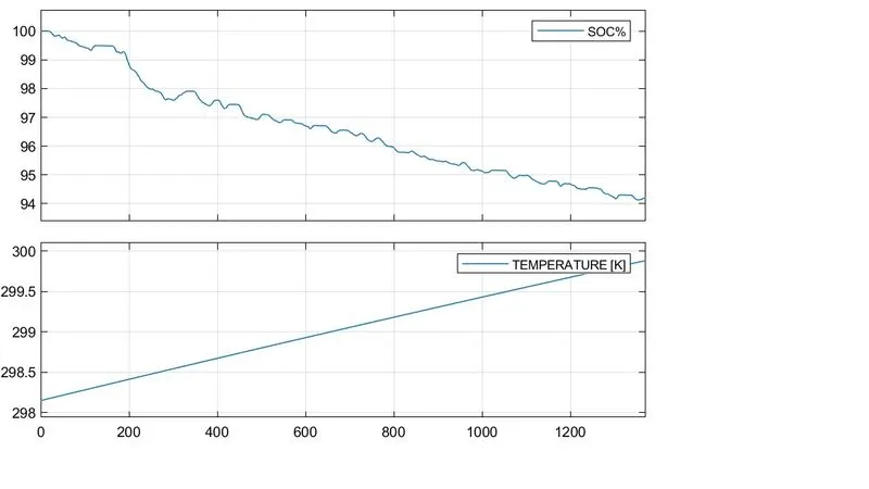
- The plot results shows the SOC of the battery module is decresed from 100% to 95.8% at the end of UDDS drive cycle.
- Initial temperature of the battery is 298K.
- The temperature of the battery module increase from 298 K to 300 K.
- The overall temperature of the battery pack is increased throught the cycle.
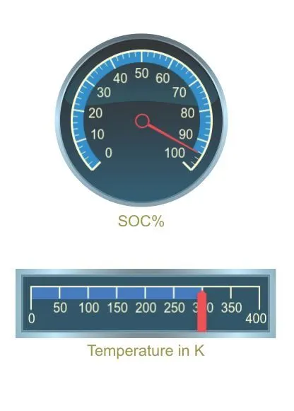
Dashboard results for case 3:
The dash board shows the final SOC % and temperature of the battery module at the end of drive cycle.
CONCLUSION OF MODEL 1:
The 10 cell series lithium ion battery model is simulated for three different temperatures - 10 deg,25 deg,45 deg celcius, here we observed that the temperature of the battery pack increases, discharge rate is high and the Depth of Discharge is increases which means more drain of SOC.
MODEL 2:
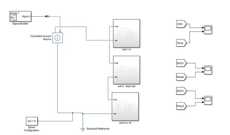
We can also model the 10 cell series by splitting and introducing the fault cell,here we split the 10 cell to 1-4 cell, fault cell 5th cell and cell 6 to 10.
The simulink model of 10 cell series with fault cell is given below:
Simulink model:
Cell 1 to 4:
Cell 5 (fault cell):
Resistance of 10 ohms is added to the battery model
Cell 6 to 10:
PLOT RESULTS:
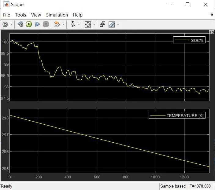
Module 1 (cell 1 to 4):
Module 2 (cell 5):
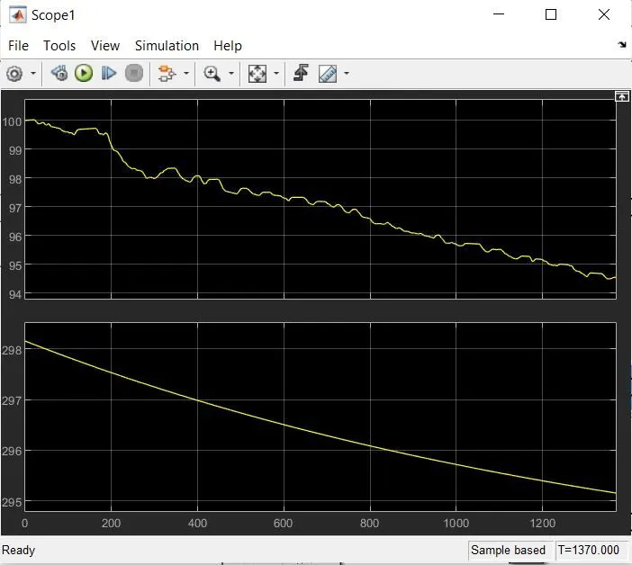
Module 3 (cell 6 to 10):
CONCLUSION OF MODEL 2:
Here, we split the 10 cell series to 3 modules,module 1(1 to 4 cells),module 2 (5th cell),module 3 (6 to 10 cell)
same temperature is given to all the modules and the characteristics are studied.
CONCLUSION:
10 cell series lithium ion battery model is created in MATLAB and the thermal effects of the battery model is simulated.
Two model is created one with 10 series of battery model and another one with 3 modules.
Two model is simulated with various temperatures and charge and discharge rates are plotted and characteristics are studied and observed.
Thank you
Submitted by
B.Riyaz