Project 2 Thermal modeling of battery pack
EV LIVE BATCH:-21
Project 2 Thermal Modeling of Battery Pack
Aim:- To Simulate the Thermal Effect of 10 cell Series Lithium ion battery model & to compare the Life cycle performance at Various temperature,Charge & Discharge rates using simulink.
Required Blocks for creating Simulink Model:-
- Battery(Table-Based)
- Controlled Current Source
- From Workspace
- Controlled Temperature Source
- Convective Heat Transfer
- Constant block
- Thermal Reference
- Electrical Reference
- Solver Configuration Block
- PS-Simulink converter
- Simulink-PS converter
- Add block
- Scope
- Subsystem block
- Connection Port (PMC_Port)
Model Description:-
- Actually, we have to take 10 Lithium ion cells & then connect them in series i.e:- +ve terinal of 1st cell should connect with -ve terminal of 2nd cell & so on as follows:-

- To reduce the complexity of the model, we will divide this connections into 2 sets of 5 cells in series & place then in separate subsystems.
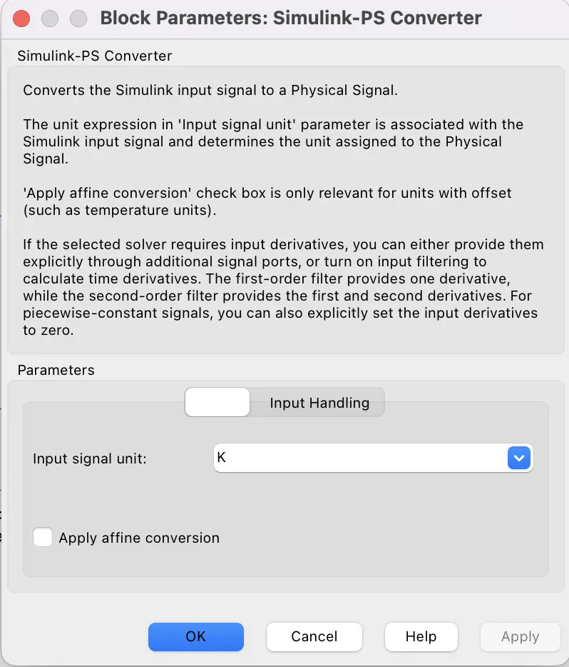
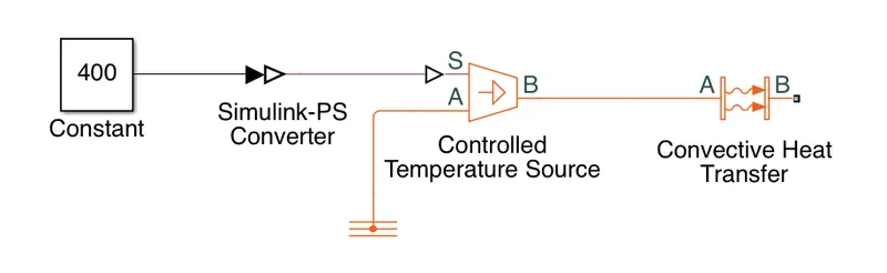
- Take Controlled temperature source, & connect the S terminal with a constant block through Simulink-PS converter block whose input signal unit is set as "K" (kelvin).
- Now connect the B terminal of Controlled current source with A terminal of Convective Heat Transfer Block & connect the Thermal Reference with the A teminal of Controlled Temperature Source.
- Take a subsystem & named it as "Subsystem 1", then open that subsystem & connect 5 Cells (Table-Based Battery) in series.
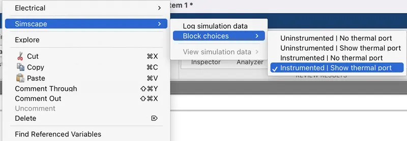
- Then Right click on a battery & go to Simscape ---> Block Choices ---> Instrumented | Show Thermal port.
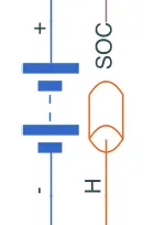
- Then the battery will consist of 4 ports such as +ve,-ve,SOC & H terminal for Thermal conuctor.
- We have to do the same thing with all 5 batteries.
- Then Take three PCM_Ports & change the locations of 2 ports as Left which means that these two will be the inputs for the subsystem & change the location of 3rd PCM_Port as Right which will represent the Output of Subsustem.
- 1st input for the subsystem will be "Battery-1 (+ve)" which represents the +ve terminal of 1st battery & the 2nd Input will be "Thernal Port" which will carry the Heat from the Covective Heat Transfer block.
- Output for this subsystem will be "Battery-5 (-ve)" which represents the -ve terminal of the 5th battery.
- Then connect SOC of every battery with PS-Simulink Converter & then take a add block & connect output from 6 PS-Simulink converter block with Add block which will give the resultant SOC of 5 batteries in series.
- then the Output from the Add block has to be connected with a Outport.
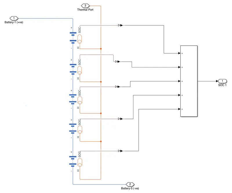
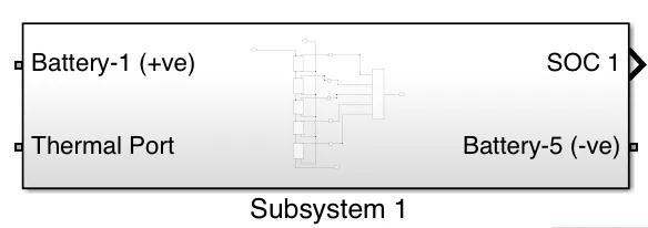
- In the same way we have to create another subsystem which consists of anothe 5 cells in series (From 6th battery to 10th battery) & is named as "Subsystem 2".
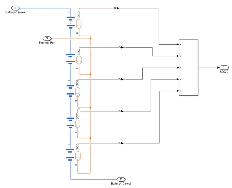
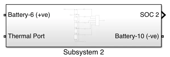
- Now connect the Battery-5 (-ve) with Battery-6 (+ve) so that total 10 batteries are connected in series now & forms a complete Battery Pack with 10 cells in series.
- Now call the UDDS current profile into the Base Workspace. UDDS current profile is nothing but it is a drive cycle data in the form of Current vs time.where Charging & discharging of battery take place in different times.
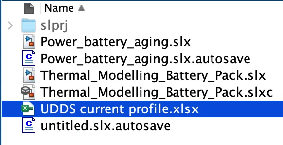
- In order to do that, we have to double click on the "UDDS current profile.xlsx" which is a Excel file.
- then select Coulumb A & B, chage the Output type as Numeric matrix.
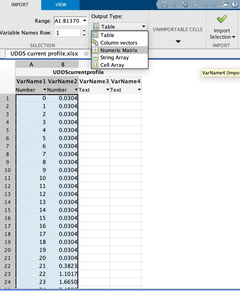
- Then click on Import selection. now the UDDS current profile has stored sucessfully in the base workspace.

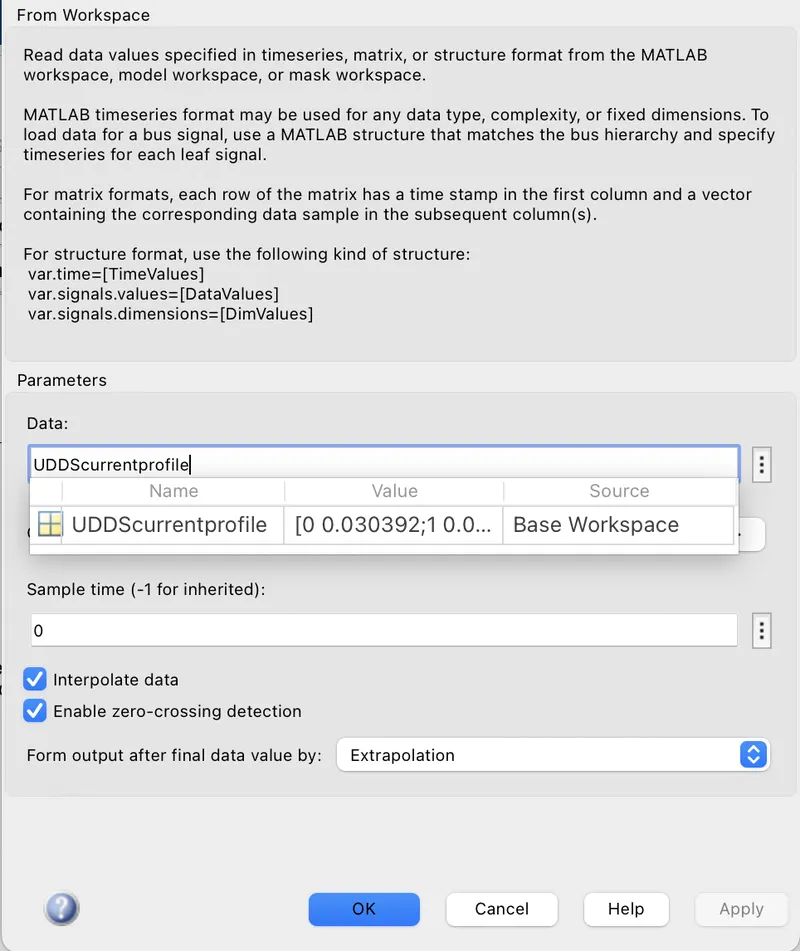
- Now take From Workspace block & give the data as UDDScurrentprofile which should match the name with the file stored in the base workspace.
- connect it with S terminal of Controlled Current Source.
- Then connect the +ve terminal of Controlled current source with The -ve terminal of battery pack [i.e:- Battery-10 (-ve)]
- Connect the -ve terminal of Controlled Current Source with the +ve terinal of Battery Pack [i.e:- Battery-1 (+ve)]
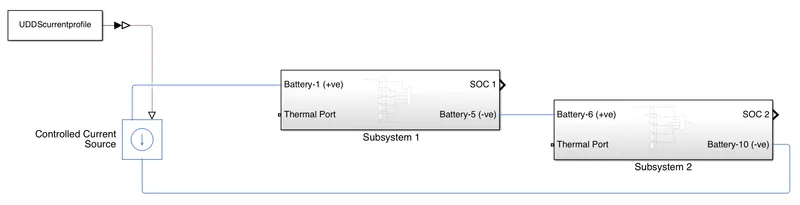
- Now connect the B terminal with the Thermal Ports of both Subsystems.
- Then connect SOC 1 & SOC 2 with another Add block whose output will give the summation of SOC of 10 cells in series.
- Then connect the scope with the Output from the Add block. & with the UDDS current profile also.
- Then connect a Electrical Reference & Solver configuration block with -ve terminal of battery pack.
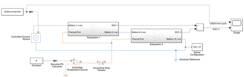
- Now the Model is ready to simulate.
Results:-
(A) At Room Temperature of 298.15 K (25 degree celsius):-
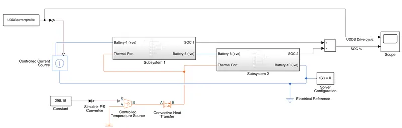
- Here we have taken temperature of 298.15 Kelvin or 25 degree celcius & then run the model for 500sec.
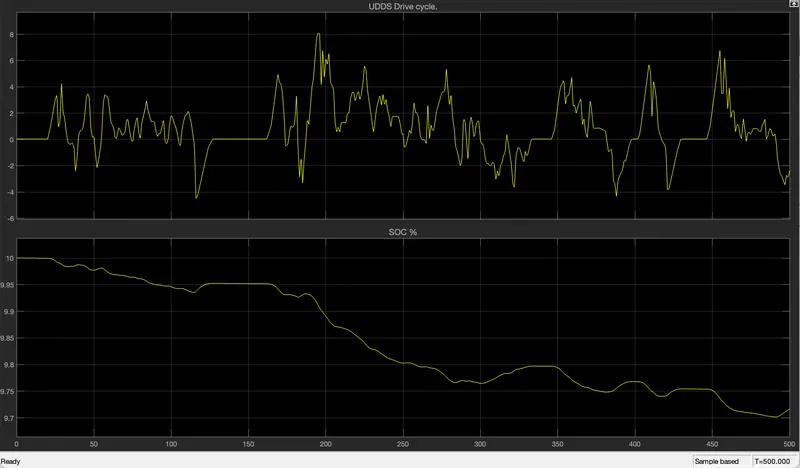
- Here we can see that, there are various stages in the UDDS current Profile grapgh such that when the current value is 0 then the vehicle is at standby mode, at that time SOC value neither decreases mor increases. i.e:- SOC remains constant.
- when the current value increases or current value is +ve then the vehicle is in driving mode, at that time battery pack discharges so SOC value decreases during driving mode.
- When the current value decreases or -ve value then the vehicle is said to be in regenerative braking mode condition, at that time battery pack is in charging mode. so SOC value increases during charging mode i.e:- during the -ve current value.
- Initially the SOC of battery pack is at 100%.
- after 500sec,at room temperature of 298.15K under various Charge & discharge cycles, 97.2% of SOC is remaining in the battery pack.
- so we can say that at 298.15 K of temperature, 10 cell series battery pack has 2.8% loss in the SOC.
(B) At 35 degree celsius or 308.15K Temperature:-
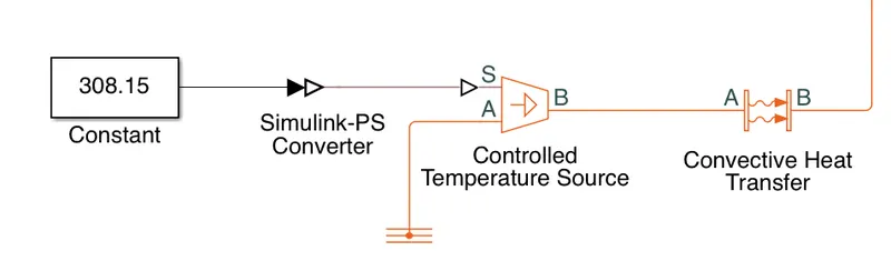
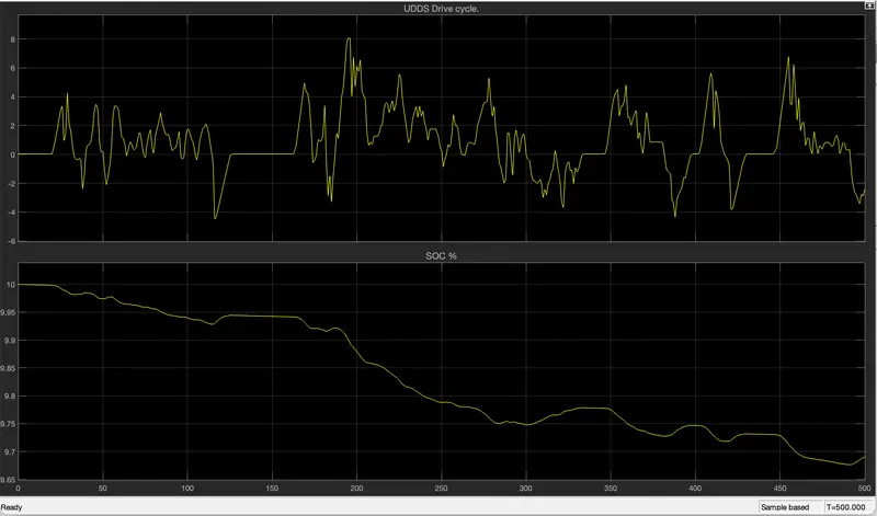
- Here we have increased the temperature from 25 degree celsius to 35 degree celcius.
- Then, initially the SOC of the battery pack was 100%
- Then after 500sec, at 35 308.15 K temperature under various charge & discharge cycles, SOC of the battery pack reaches at 96.8%.
- so we can say that there is 3.2% loss in SOC of the battery pack at 35 degree celsius.
(C) At 45 Degree celsius or 318.15 K temperature:-
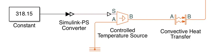
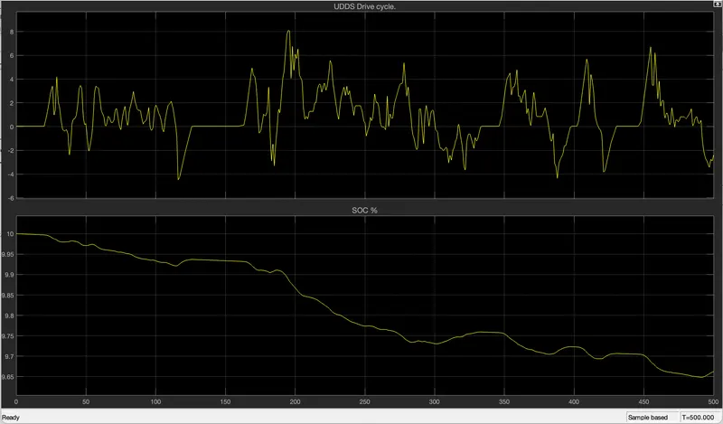
- Here we have again increased the temperature for the battery pack from 35 degree celsius to 45 degree celsius.
- intially the SOC of battery pack was 100%.
- after 500sec, at 45 degree celcius or 318.15 K temperature under various charge & discharge cycles, SOC of battery pack reaches at 96.6%.
- so there will be 3.4% loss in SOC of battery pack at 45 degree celsius.
(D) At 55 Degree celsius or 328.15 K temperature:-
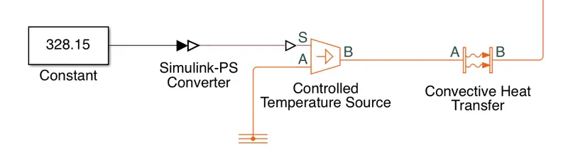
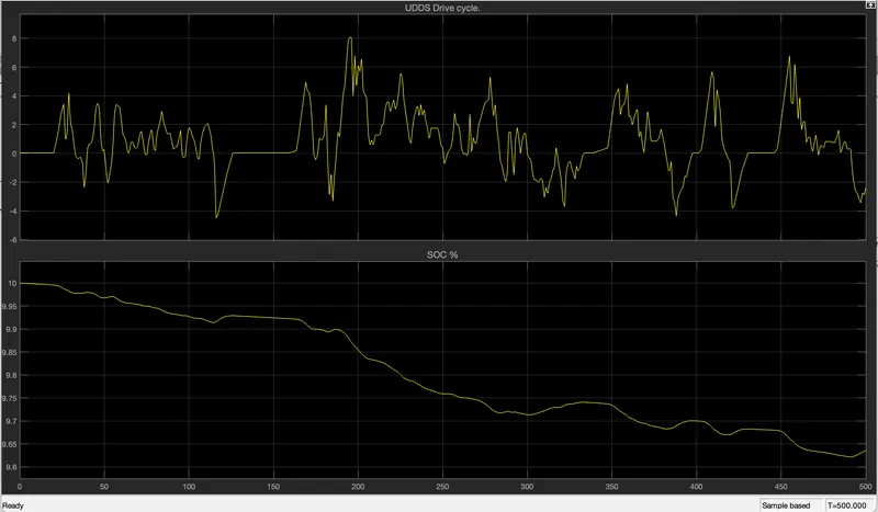
- Here we have increased the temperature for the battery pack from 45 degree celsius to 55 degree celsius.
- Initially,SOC of the battery pack was 100%.
- then after 500sec,at 328.15 K temperature under various Charge & discharge cycles, the SOC of battery pack has reached at 96.4%.
- So there is 3.6% loss in SOC of 10 cell series Battery pack at 55 degree celsius.
(E) At 65 Degree Celsius or 338.15 K Temperature:-
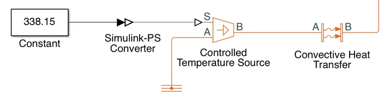
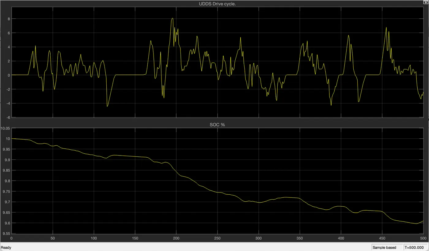
- Here we have again increased the temperature for battery pack from 55 degree celsius to 65 degree celsius.
- Intially, SOC of the battery pack was 100%.
- Then after 500sec, at 65 degree celsius temperature under various charge & discharge cycle, SOC of battery pach has reached at 96.1%.
- so there is 3.9% loss in SOC of battery pack at 65 degree celsius.
Tabulation:-
- Here we have prepared a tabulation for Change in SOC of battery pack at various temperature under variuos charge & discharge cycles.
| Simulation time (Sec) | Temperature (Degree Celsius) | Initial SOC of Battery Pack (%) |
Final SOC of Battery Pack (%) |
Loss in SOC (%) |
| 500 | 25 | 100 | 97.2 | 2.8 |
| 500 | 35 | 100 | 96.8 | 3.2 |
| 500 | 45 | 100 | 96.6 | 3.4 |
| 500 | 55 | 100 | 96.4 | 3.6 |
| 500 | 65 | 100 | 96.1 | 3.9 |
Conclusion:-
- We have sucessfully created a simulink model for 10 Lithium ion cells in series to check the performance of battery pack under various temperature & various charge & discharge cycles.
- We changed the temperature as 298.15K,308.15K,318.15K,328.15K & 338.15K repectively.
- We have used UDDS current profile for different charge & discharge cycles.
- from the result scopes & tabulation, we can conclude that for 500sec simulation of the model, SOC of battery pack decreases slowly by increasingh the temperature.
- but if we increase the simultion time, then theSOC of the battery will varry more at various temperature.
- But the conclusion is, by increasing the temperature, SOC of 10 cells series battery pack decreases.