Project 2 Adaptive Cruise Control
EV LIVE BATCH:-21
Ans:-
Adaptive Cruise Control (Main Project)
Aim:-
- Main aim of this Adaptive Cruise Control project is to control the the speed & acceleration of drive vehicle by measuring the speed of lead vehich & the distance gap between lead vehicle & drive vehicle.
- here drive vehicle means the vehicle in which Adaptive Cruise Control algorithim is implemented & the vehicle ahead of drive vehicle is called as Lead vehicle.
- by implementing this ACC technology in a vehicle, we can reduce the chance of accidental case.
- Driver can feel relax, can concentrate the road little better & enjoy the vehicle riding by implementing ACC mode.
- Since Adaptive Cruise Control is a comfort and convenience system, brake interventions and vehicle acceleration only take place within defined limits.
Objective:-
- Developing Adaptive Cruise Control feature as per the Requirement Document using MATLAB Simulink.
- Follow all the MBD related processes: Requirement Tagging & Traceability, SLDD creation, Configuration Parameter changes, Model Advisor check & Code Generation.
- In Configuration Parameters: enable “Support Floating Numbers” under Code Generation settings.
- Use Embedded Coder to generate the code.
- If choosing code generation, Storage class for Input signals: ImportedExtern; Storage class for Output signal: Export to File; Storage class for local signals: localizable; Storage class for calibration signals: Const.
- Choose sample time for all signals as 0.01s
Description About Modelling of ACC Model:-
- 1st create a new simulink blank model page & named it as Adaptive_Cruise_Control_Main_Project then save it a separate folder.
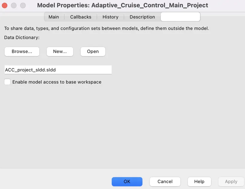
- then go to Modelling tabs & Ckick on 'Link to Data Dictionary', then create a new sldd file with name Vehicle_Direction_sldd & save it in the save folder where the ceated simulink model is present. & we have to uncheck the box while we are creating the new sldd file otherwise datas from the base workspace will link with the model blocks.
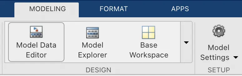
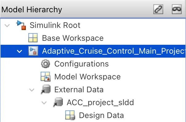
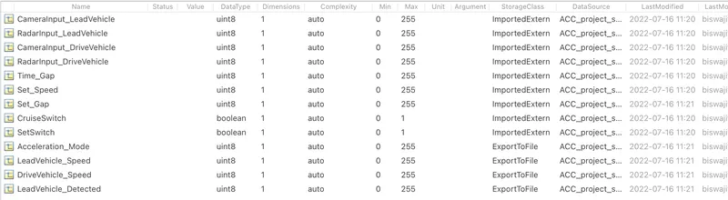
- after creating the sldd file, again click on the Modelling tab then go to the Model explorer then expand the External data below the model name then we can see there the sldd file which have created before then expand that sldd file then click on the Design Data then we have to enter values & properties of input signals, output signals & the constant parameters from the table given in the question such as:-
-
Signals & Calibration Data List:
Signal / Calibration Name
Signal Type
Data Type
Dimension
Min
Max
Initial Value
Units
CameraInput_LeadVehicle
Input
Uint8
1
0
255
-
-
RadarInput_LeadVehicle
Input
Uint8
1
0
255
-
-
CameraInput_DriveVehicle
Input
Uint8
1
0
255
-
-
RadarInput_DriveVehicle
Input
Uint8
1
0
255
-
-
Time_Gap
Input
Uint8
1
0
255
-
-
Set_Speed
Input
Uint8
1
0
255
-
-
Set_Gap
Input
Uint8
1
0
255
-
-
CruiseSwitch
Input
Boolean
1
0
1
-
-
SetSwitch
Input
Boolean
1
0
1
-
-
Acceleration_Mode
Output
Uint8
1
0
255
-
-
LeadVehicle_Speed
Output
Uint8
1
0
255
-
-
DriveVehicle_Speed
Output
Uint8
1
0
255
-
-
LeadVehicle_Detected
Output
Uint8
1
0
255
-
-
- we have to enter these values & all information of all type signals inside the Design data to store inside the sldd file. such as:-
- then take a Subsystem from the simulink library browser & then open that subsystem & disconnect the inport from the outport.
- According to the questtion, we have 3 requirements for this model. every requirement has some logic between the input signal & output signals. so we have to take 3 subsystem to implement the logics fpr 3 requirements.
- Requirement-1 Lead-Vehicle:-
According to the question the requirement 1is given as :-
- Lead Vehicle is a vehicle which is driving in the road ahead of our drive vehicle. Two input signals (Signal Name: CameraInput_LeadVehicle & RadarInput_LeadVehicle).
- Ideally sensor fusion techniques will be deployed to process & analyze data from camera & radar. For complexity reasons, let’s not adapt to any such algorithms.
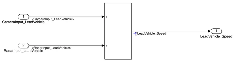
- We can simply add both the radar & camera inputs & the corresponding output is read as Speed profile output (Signal Name: LeadVehicle_Speed).
- Speed data of the lead vehicle is critical in implementing the Adaptive Cruise Control algorithm.
- This requirement is for lead vehicle. it is a vehicle which run infront of drive vehicle.
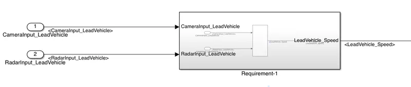
- take a subsystem & named it as Requirement-1.
- then open that subsystem & disconnect inport from outports which is previously connected.
- according to the Requirement-1, we have two inputs such as CameraInput_LeadVehicle & RadarInput_LeadVehicle) so take copy & paste the inport present previously & named these inports as same as the name of input signals i.e:- give name to inport1 as CameraInput_LeadVehicle & the inport2 as RadarInput_LeadVehicle.
- take one add block from the library browser & connect two inport signals with that add block.
- then connect the output of the add block with outport.
- this outport will carry the final output signal of the requirement-1 i.e:- LeadVehicle_Speed.
- now the Requirement-1 subsystem is completed.
2. Requirement-2 Drive Vehicle:-
As per the question, the Requirement-2 has given as:-
- Drive Vehicle is the vehicle driven by the user & this is the vehicle which has ACC algorithm in it.
- Like the Lead Vehicle, Drive Vehicle algorithm also has 2 input signals (Signal Name: CameraInput_DriveVehicle, RadarInput_DriveVehicle) & one signal coming as an Input to this subsystem (Signal Name: Acceleration_Mode) – three inputs into this requirement in total.
- Like the above requirement, sensor fusion techniques will also be deployed here, for complexity reasons we are ignoring them.
- Two output signals come from this subsystem (Signal Name: DriveVehicle_Speed & LeadVehicle_Detected).
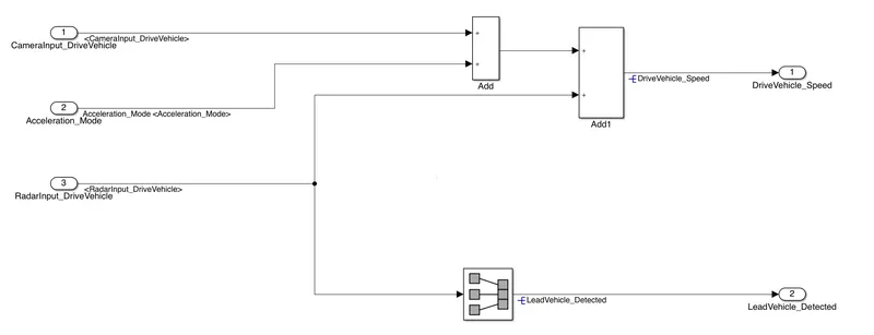
- Signal DriveVehicle_Speed is summation of three input signals mentioned above & LeadVehicle_Detected is renamed from Input Signal RadarInput_DriveVehicle by mere use of Signal Conversion block.
- Take a subsystem for this requirement & named it as Requirement-2.
- then open the subsystem & disconnect outport from the inport.
- then take 2 extra inports, two add blocks, 1 signal conversion block & 1 extra outport block from the library browser.
- as per the requirement-2, we have 3 input signals such as CameraInput_DriveVehicle, RadarInput_DriveVehicle , Acceleration_Mode & two output signals such as DriveVehicle_Speed & LeadVehicle_Detected.
- then we have to name the inports & outport blocks same as the i/p signals & output signals.
- then connect CameraInput_DriveVehicle & Acceleration_Mode input signals with one add block then again connect the the 2nd add block with RadarInput_DriveVehicle signal & the output of 1st add block.
- then connect a signal conversion block with RadarInput_DriveVehicle signal & output of that signal conversion block will be connected with LeadVehicle_Detected outport block.
- then connect the output of 2nd add block with the DriveVehicle_Speed outport block.
- now the logics are implemented according to Requirement-2.

3. Requirement-3 Adaptive Cruise Control Algorithm:-
According to the question, Requirement-3 has given as,
- Adaptive Cruise Control feature has 3 major modes of operation: OFF Mode, STANDBY Mode & ON Mode. This particular requirement has to be implemented as state machine logic in Simulink.
- The input signals to this state machine system are (Signal Name: Time_Gap, Set_Speed, Set_Gap, CruiseSwitch, SetSwitch).
- Also, the output signals (Signal Name: DriveVehicle_Speed & LeadVehicle_Detected) from requirement-2 is fed back as an input signal into this state machine block.
- Additionally, output signal (Signal Name: LeadVehicle_Speed) from requirement-1 is given as an input signal to this state machine block as well.
- Output from this subsystem is a signal (Signal Name: Acceleration_Mode) which governs the vehicular speed of the drive vehicle which automatically adjusts its speed & velocity to match the lead vehicle.
- As per the requirement-3, we have do the logics inside a state machine chart.
- the chart will mainly containing three modes such as OFF mode, Standby mode & ON mode.
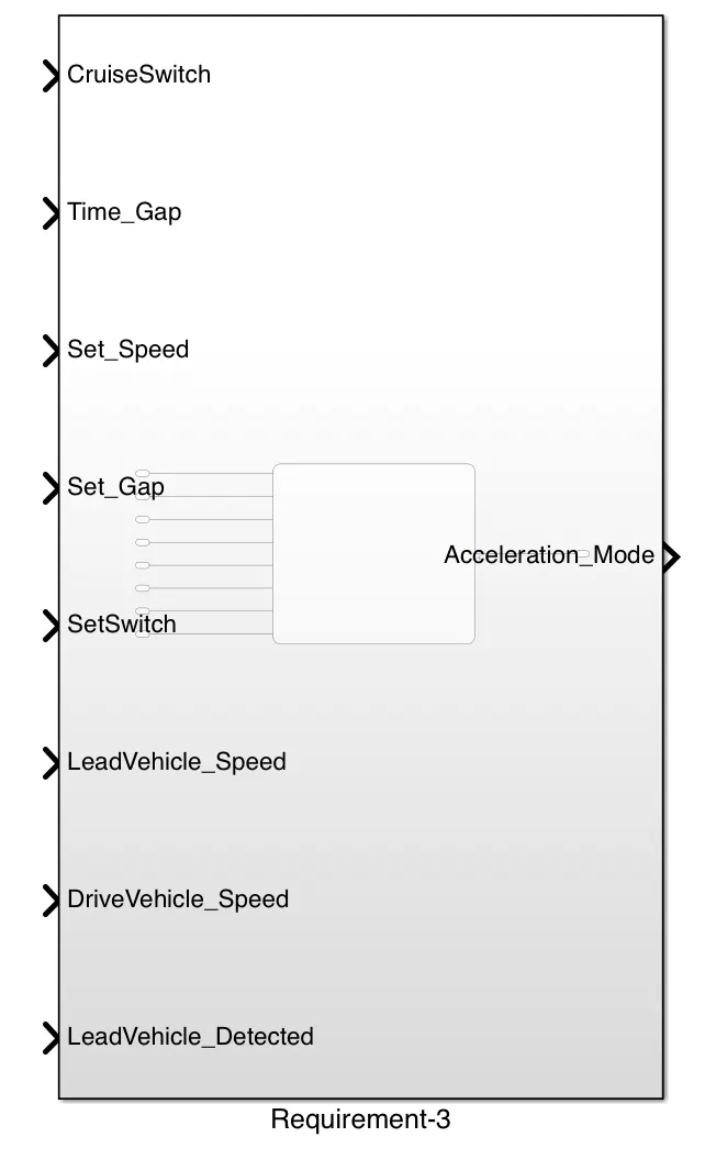
- for this requirement we need 8 no. of input signals such as Time_Gap, Set_Speed, Set_Gap, CruiseSwitch, SetSwitch & DriveVehicle_Speed , LeadVehicle_Detected which are coming from the output of Requirement-2 subsystem & last input signal is LeadVehicle_Speed which is the output signal of Requirement-1 subsystem.
- the output of the Requirement-3 is Acceleration_Mode.
- now take separate subsystem & named it as Requirement-3.
- Now we have to create a state machine chart inside the Requirement_3 subsystem & named it as ACC_Logic.
- open the Requirement-3 subsystem & take chart block from the library browser.
- now we have to implement the logics for OFF mode,Standby mode & ON mode as per the next requirements.
3.(i). Requirement 3a – ACC OFF MODE state logic:
As per the question the requirement 3a is given as,
- This is the default state inside state machine logic. Output signal Acceleration_Mode is at value 0 in this state.
- This state is governed by input signal CruiseSwitch.
- If CruiseSwitch is equal to 1, state ACC STANDBY mode will get activated. If CruiseSwitch is equal to 0, state ACC OFF mode will get activated, from either ACC ON mode or ACC STANDBY mode
- Take a state which will be the default inside the ACC_Logic chart.
- then give name the default state as ACC_OFF_MODE
- as per this requirement 3a, output signal Acceleration_Mode is 0 in this state.
- so give condition as, entry:Acceleration_Mode =0;
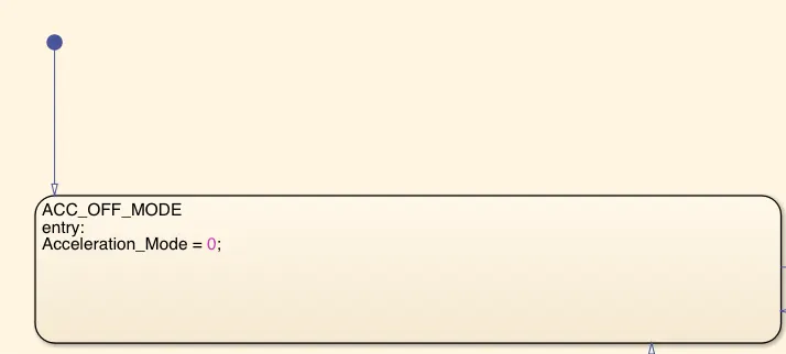
- here we have two contions to transient from This state to next states such as
- If CruiseSwitch is equal to 1, state ACC STANDBY mode will get activated. If CruiseSwitch is equal to 0, state ACC OFF mode will get activated, from either ACC ON mode or ACC STANDBY mode
- we can see these transient condition in next procedure of next state.
3.(ii) Requirement 3b– ACC STANDBY MODE state logic:
As per questioin, Requirement 3b has given as,
- This is the second activated state inside state machine logic. Output signal Acceleration_Mode is at value 1 in this state.
- This state is governed by both input signals CruiseSwitch & SetSwitch.
- If CruiseSwitch is equal to 1, state ACC STANDBY mode will get activated. If CruiseSwitch is equal to 0, state ACC OFF mode will get activated, from either ACC ON mode or ACC STANDBY mode
- If SetSwitch is equal to 1, state ACC ON mode will get activated. If SetSwitch is equal to 0, state ACC STANDBY mode will get activated.
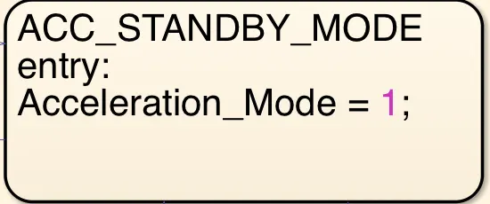
- Take another state & named it as ACC_STANDBY_MODE
- then give command as entry: Acceleration_Mode ==1;
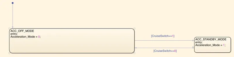
- take a transition from ACC_STANDBY_MODE to ACC_OFF_MODE & give the input condition as [CruiseSwitch==0] then when the CruiseSwitch is 0 then the vehicle is going to OFF mode from STANDBY_MODE state.
- take another transition from ACC_OFF_MODE to ACC_STANDBY_MODE & give the condition as [CruiseSwitch==1] i.e:- when CruiseSwitch is equal to 1, then the OFF mode will deactivated & the STANDBY mode will activated.
3.(iii) Requirement 3c – ACC ON MODE state logic:
as per the question, Requirement 3C has given as,
This state will be activated when input signal SetSwitch is equal to 1. There are 6 sub states to this state logic: They are:
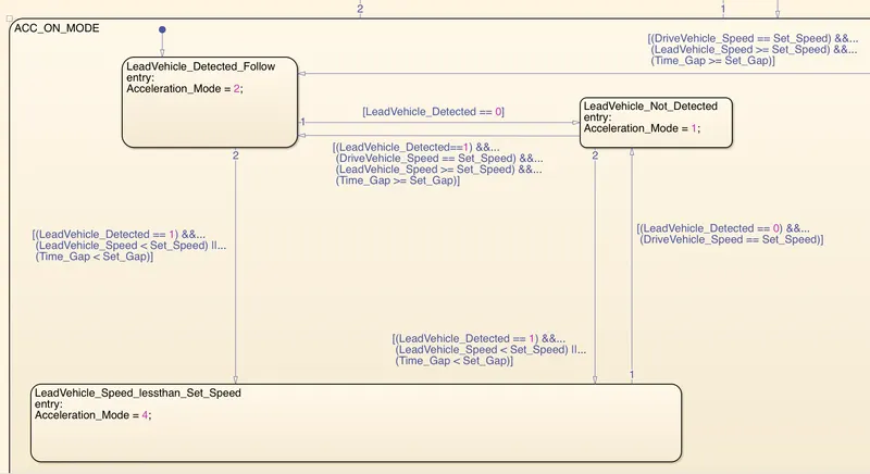
- LeadVehicle_Detected_Follow (Default)
- LeadVehicle_Not_Detected
- LeadVehicle_Detected_Resume
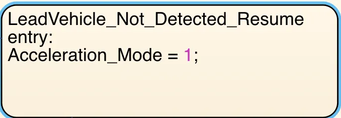
- LeadVehicle_Not_Detected_Resume
- LeadVehicle_Speed_lessthan_Set_Speed
- LeadVehicle_Speed_equal_Set_Speed
- Take a new state & named it as ACC_ON_MODE
- as per the requirement 3c, this ACC_ON_STATE will conist of 6 states separetely.
- we have to insert 6 states inside this ACC_ON_STATE
- take a transition having condition as [CruiseSwitch==0] & connect it from ACC_ON_STATE to ACC_OFF_STATE.
- take another transition from this on stste to ACC_STANDBY_MODE with condition as [SetSwitch==0]
- take another transition from the standby mode to ACC on mode with condition as [SetSwitch==1]
- this conditions are showing that, when the SetSwitch is 1 then ACC_ON_MODE will activate & when SetSwitch is 0 then the ACC_STANDBY_MODE will activate.
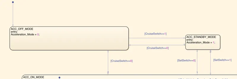
- then insert 6 states inside the ACC_ON_STATE & give name as LeadVehicle_Detected_Follow, LeadVehicle_Not_Detected, LeadVehicle_Detected_Resume, LeadVehicle_Not_Detected_Resume, LeadVehicle_Speed_lessthan_Set_Speed, LeadVehicle_Speed_equal_Set_Speed.
3.(iv) Requirement 3c (i) – LeadVehicle_Detected_Follow (ACC ON MODE):
As per question, Requirement 3c(i) has given as,
- This is the default sub state inside ACC ON MODE state. Output signal Acceleration_Mode is equal to 2.
- Condition to transit from LeadVehicle_Detected_Follow to LeadVehicle_Not_Detected; Input signal condition LeadVehicle_Detected == 0.
- Condition to transit from LeadVehicle_Detected_Follow to LeadVehicle_Speed_lessthan_Set_Speed; Input Signals condition (LeadVehicle_Detected == 1) && (LeadVehicle_Speed < Set_Speed) || (Time_Gap < Set_Gap).
- we have already created LeadVehicle_Detected_Follow state & now give command as entry: Acceleration_Mode = 2;
- this is the default state inside the ACC_ON_MODE state, that means, when the ACC_ON_MODE stae will activate, then this LeadVehicle_Detected_Follow state will activate 1st inside the On mode state.
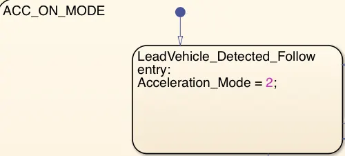
- in this requirement we have two transition paths from this state to another two states, we will discucc about that in the next steps.
3.(v) Requirement 3c (ii) – LeadVehicle_Not_Detected (ACC ON MODE):
as per the question, Requirement 3c(ii) has given as,
- Output signal Acceleration_Mode is equal to 1.
- Condition to transit from LeadVehicle_Not_Detected to LeadVehicle_Detected_Follow; Input signals condition [(LeadVehicle_Detected==1) && (DriveVehicle_Speed == Set_Speed) && (LeadVehicle_Speed >= Set_Speed) && (Time_Gap >= Set_Gap)]
- Condition to transit from LeadVehicle_Not_Detected to LeadVehicle_Speed_lessthan_Set_Speed; Input signals condition [(LeadVehicle_Detected == 1) && (LeadVehicle_Speed < Set_Speed) || (Time_Gap < Set_Gap)]
- This LeadVehicle_Not_Detected state has already created before & now give a command as entry: Acceleration_Mode == 1;
- this is the 2nd state inside the ACC_ON_MODE state.
- connect a transition line from LeadVehicle_Detected_Follow to LeadVehicle_Not_Detected with a condition as [LeadVehicle_Detected == 0]
- connect another transition from LeadVehicle_Not_Detected to LeadVehicle_Detected_Follow with a condition as [(LeadVehicle_Detected==1) && (DriveVehicle_Speed == Set_Speed) && (LeadVehicle_Speed >= Set_Speed) && (Time_Gap >= Set_Gap)].
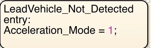
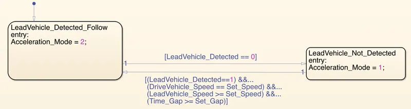
- here we can see that, there is transition is left to do, we will discuss in the next state explaination.
3.(vi) Requirement 3c (iii) – LeadVehicle_Detected_Resume (ACC ON MODE):
as per the question, Requirement 3c(iii) has given as,
- Output signal Acceleration_Mode is equal to 3.
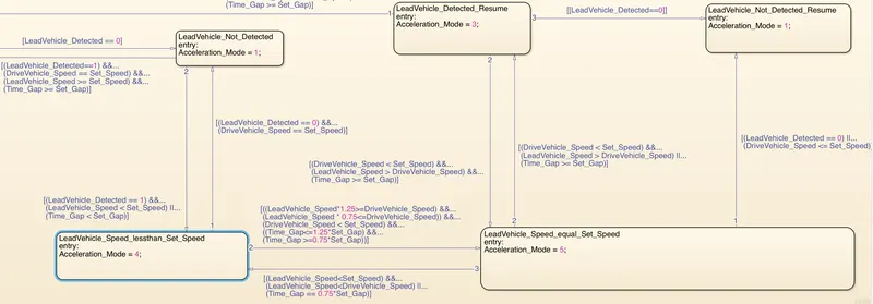
- Condition to transit from LeadVehicle_Detected_Resume to LeadVehicle_Detected_Follow; Input signals condition [(DriveVehicle_Speed == Set_Speed) && (LeadVehicle_Speed >= Set_Speed) && (Time_Gap >= Set_Gap)]
- Condition to transit from LeadVehicle_Detected_Resume to LeadVehicle_Not_Detected_Resume; Input signal condition LeadVehicle_Detected==0.
- Condition to transit from LeadVehicle_Detected_Resume to LeadVehicle_Speed_equal_Set_Speed; Input Signal condition [(DriveVehicle_Speed < Set_Speed) && (LeadVehicle_Speed > DriveVehicle_Speed) && (Time_Gap >= Set_Gap)]
- this state has created before, so give command as entry: Acceleration_Mode = 3;
- connect a transition from LeadVehicle_Detected_Resume to LeadVehicle_Detected_Follow state with a condition as [(DriveVehicle_Speed == Set_Speed) && (LeadVehicle_Speed >= Set_Speed) && (Time_Gap >= Set_Gap)]
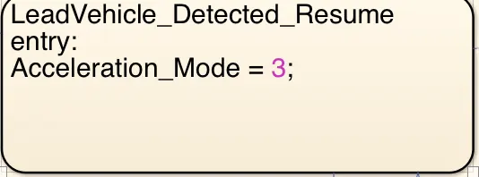

- we can see that there are 2 conditions are left to do, so we will discuss them in the next stste explaination.
3.(vii) Requirement 3c (iv) - LeadVehicle_Not_Detected_Resume (ACC ON MODE):
as per the question, Requirement 3c(iv) has given as,
- Output signal Acceleration_Mode is equal to 1.
- this state is created before & now give a command as entry: Acceleration_Mode = 1;
- connect a transition from LeadVehicle_Detected_Resume to LeadVehicle_Not_Detected_Resume state with a condition as [LeadVehicle_Detected==0]

3.(viii) Requirement 3c (v) - LeadVehicle_Speed_lessthan_Set_Speed (ACC ON MODE):
As per the question, Requirement 3c(iv) has given as,
- Output signal Acceleration_Mode is equal to 4.
- Condition to transit from LeadVehicle_Speed_lessthan_Set_Speed to LeadVehicle_Not_Detected; Input signal condition [(LeadVehicle_Detected == 0) && (DriveVehicle_Speed == Set_Speed)]
- Condition to transit from LeadVehicle_Speed_lessthan_Set_Speed to LeadVehicle_Speed_equal_Set_Speed; Input signals condition [((LeadVehicle_Speed*1.25>=DriveVehicle_Speed) && (LeadVehicle_Speed * 0.75<=DriveVehicle_Speed)) && (DriveVehicle_Speed < Set_Speed) && ((Time_Gap<=1.25*Set_Gap) && (Time_Gap >=0.75*Set_Gap))]
- this state has created already before & now give a command as entry: Acceleration_Mode = 4;
- take a transition from LeadVehicle_Speed_lessthan_Set_Speed to LeadVehicle_Not_Detected state with a condition as [(LeadVehicle_Detected == 0) && (DriveVehicle_Speed == Set_Speed)]
- connect another transition from LeadVehicle_Detected_Follow to LeadVehicle_Speed_lessthan_Set_Speed state with a condition as [(LeadVehicle_Detected == 1) && (LeadVehicle_Speed < Set_Speed) || (Time_Gap < Set_Gap)]
- connect another transition from LeadVehicle_Not_Detected to LeadVehicle_Speed_lessthan_Set_Speed state with a condition as [(LeadVehicle_Detected == 1) && (LeadVehicle_Speed < Set_Speed) || (Time_Gap < Set_Gap)]

- here one transition condition has left, we will discuss in the next state explaination.
3.(ix) Requirement 3c (vi) - LeadVehicle_Speed_equal_Set_Speed (ACC ON MODE):
as per the question, Requirement 3c(vi) has given as,
- Output signal Acceleration_Mode is equal to 5.
- Condition to transit from LeadVehicle_Speed_equal_Set_Speed to LeadVehicle_Not_Detected_Resume; Input signal conditions is [(LeadVehicle_Detected == 0) || (DriveVehicle_Speed <= Set_Speed)]
- Condition to transit from LeadVehicle_Speed_equal_Set_Speed to LeadVehicle_Detected_Resume; Input signal conditions [(DriveVehicle_Speed < Set_Speed) && (LeadVehicle_Speed > DriveVehicle_Speed) || (Time_Gap >= Set_Gap)]
- Condition to transit from LeadVehicle_Speed_equal_Set_Speed to LeadVehicle_Speed_lessthan_Set_Speed; Input signals conditions [(LeadVehicle_Speed<Set_Speed) && (LeadVehicle_Speed<DriveVehicle_Speed) || (Time_Gap == 0.75*Set_Gap)]
- this state has created before also & now give a command as entry: Acceleration_Mode = 5;
- connect a transition from LeadVehicle_Speed_lessthan_Set_Speed to LeadVehicle_Speed_equal_Set_Speed state with a input signal condtion as [((LeadVehicle_Speed*1.25>=DriveVehicle_Speed) && (LeadVehicle_Speed * 0.75<=DriveVehicle_Speed)) && (DriveVehicle_Speed < Set_Speed) && ((Time_Gap<=1.25*Set_Gap) && (Time_Gap >=0.75*Set_Gap))]
- connect another transition from LeadVehicle_Speed_equal_Set_Speed to LeadVehicle_Detected_Resume state with a condition as [(DriveVehicle_Speed < Set_Speed) && (LeadVehicle_Speed > DriveVehicle_Speed) || (Time_Gap >= Set_Gap)]
- connect another transition from LeadVehicle_Speed_equal_Set_Speed to LeadVehicle_Speed_lessthan_Set_Speed state with a condition as [(LeadVehicle_Speed<Set_Speed) && (LeadVehicle_Speed<DriveVehicle_Speed) || (Time_Gap == 0.75*Set_Gap)]
- connect another transition from LeadVehicle_Speed_equal_Set_Speed to LeadVehicle_Not_Detected_Resume state with a condition as [(LeadVehicle_Detected == 0) || (DriveVehicle_Speed <= Set_Speed)]
- connect another transition from LeadVehicle_Not_Detected to LeadVehicle_Speed_lessthan_Set_Speed state with a condition as [(LeadVehicle_Detected == 1) && (LeadVehicle_Speed < Set_Speed) || (Time_Gap < Set_Gap)]

- Now the state flow is ready.
- then go to Modelling & click on Symbols Pane icon then choose data type of Acceleration_Mode signal as outout data type & choose other signals as input data type.
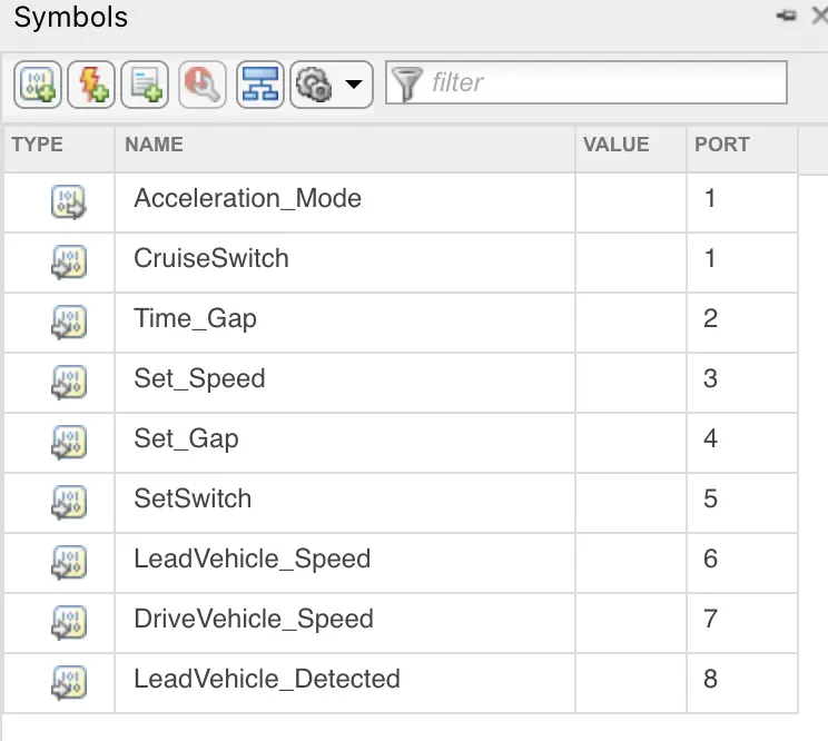
- then again go the Model Explorer & clcik on ACC_Logic option then change the data type & dimension of input & out put signals as given in the question.
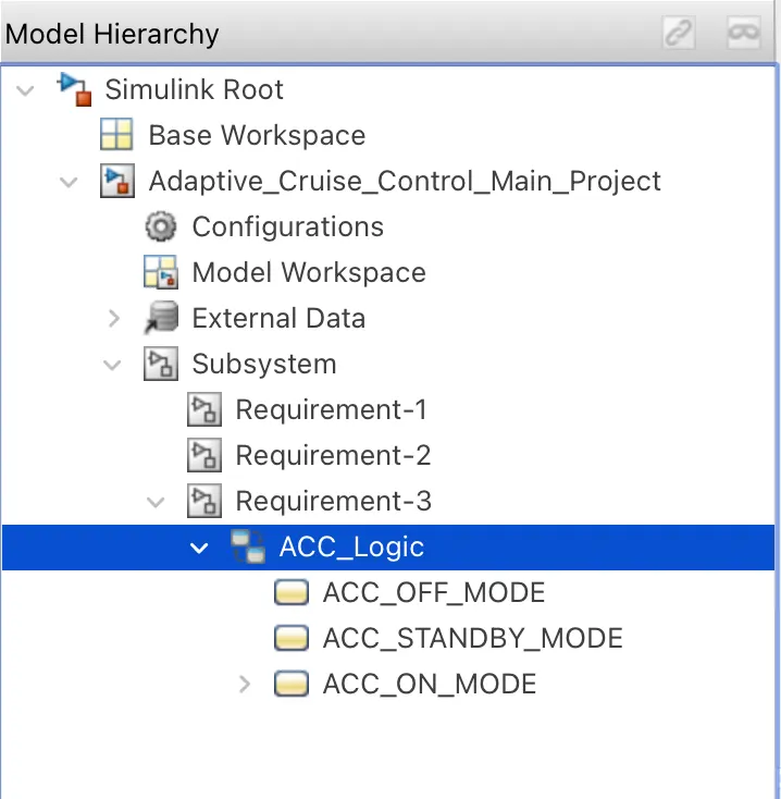
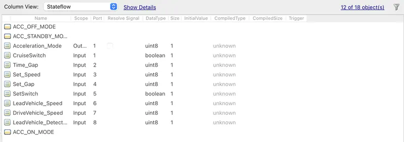
- now the state machine chart is completed for the requirement-3.
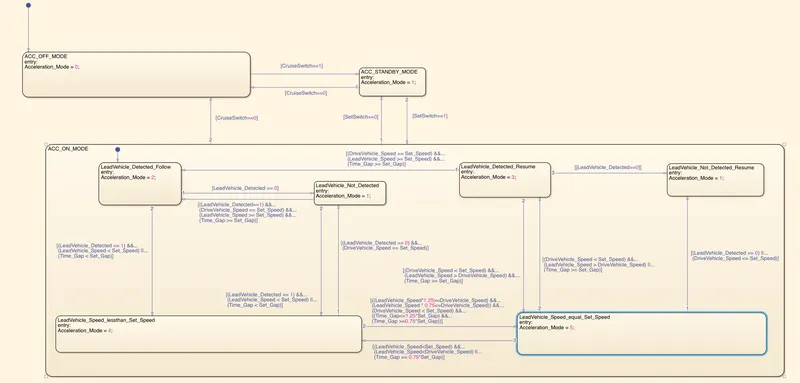
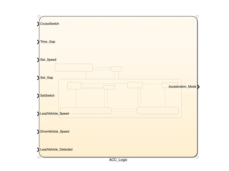
- now take 8 inport blocks & 1 outport block from the library browser, then connect with the simulink chart.
- the name of inport, outport blocks should match with the signal names.
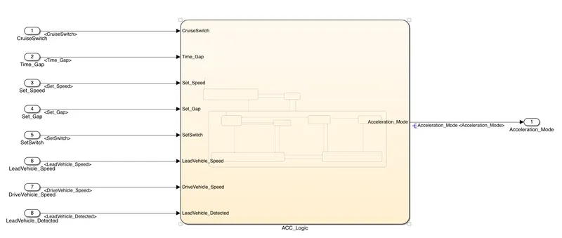
- Now go to the Requirement-3 subsystem & connect the inports with appropriate inport block & the o/p o signal with Acceleration_Mode block.
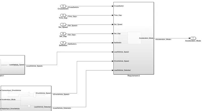
- we know that the 2nd input of requirement-2 is Acceleration_Mode signal.
- so take a Goto block & connect with the o/p of Requirement-3 subsystem.
- then take a From block & give the same name as in th Goto block.
- then connect a Unit Delay block with that From block & then connect the o/p of Unit Delay block with the 2nd input terminal of Requirement-2 subsystem. ( here Unit dellay block is a recommonded block by the simulink)
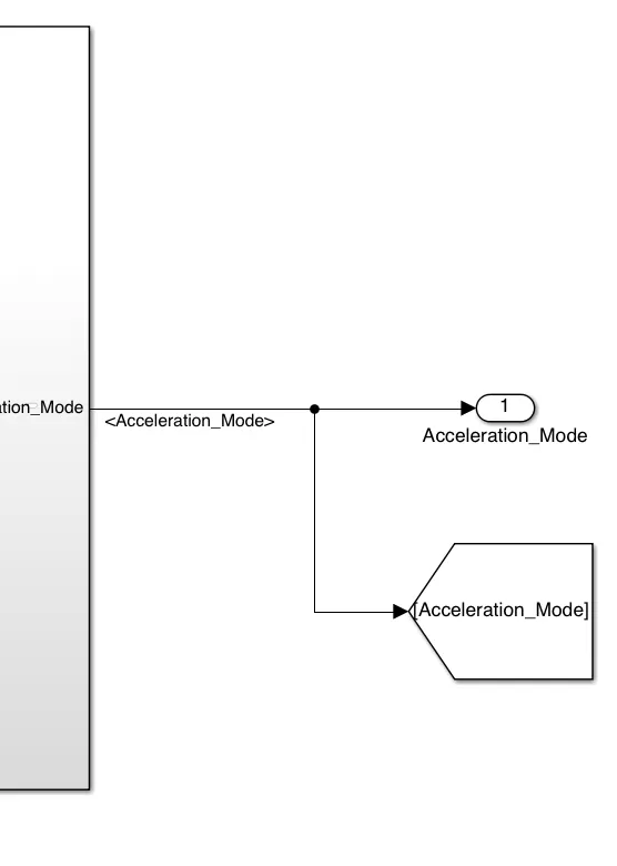

- Now all logics are implemented as per requirements.
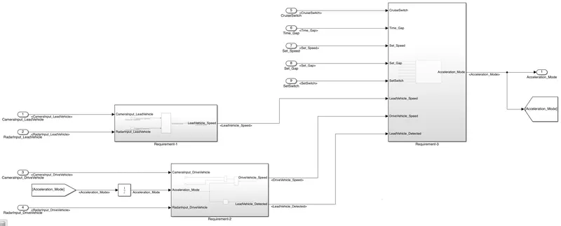
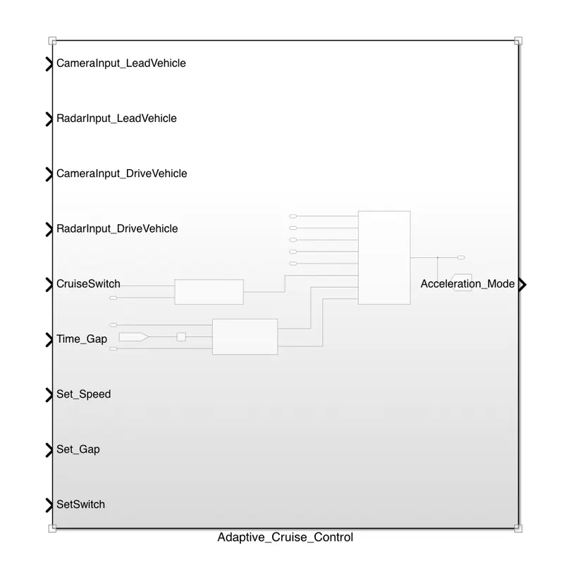
- Now the Adaptive_Cruise_Control subsystem looks as follows:-
- now take 9 inport blocks & 1 ouport block from the library browser, then give name to that blocks according to the name of input & output signals.
- then connect these blocks with appropriate signal ports of Adaptive_Cruise_Control subsystem.
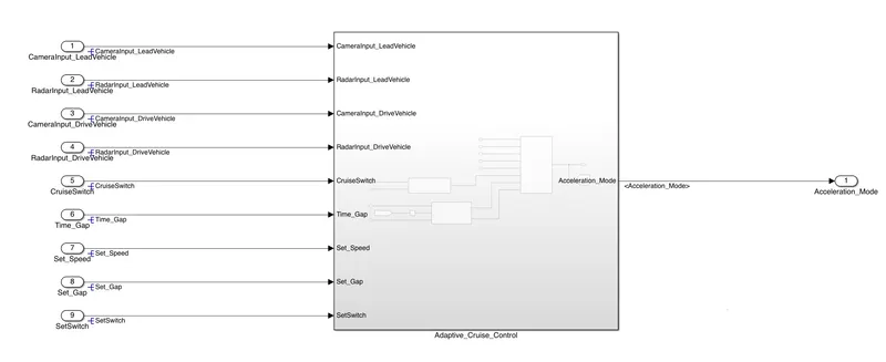
- now, we have to give the properties of signals from the sldd file by Signal Resolving & signal propagation method.
- whenever a signal appears 1st time, at that time we have to resolve the signal by double click on the signal & go to properties, then type the signal name to which we want to resolve ( the signal name must located in the sldd file alsio) then click on the "Signal name must resolve to Simulink signal object"
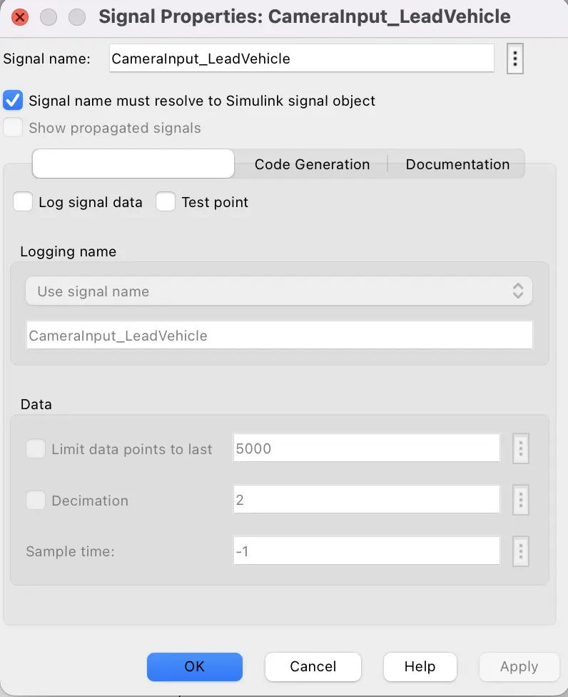
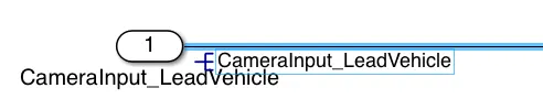
- then if agin that signal appears for next time, then we have to proagate that signal. by right click on that signal ,go to properties then click on the "show propagated signal" or double click on the signal & type <>space & enter then the signal is propagated .
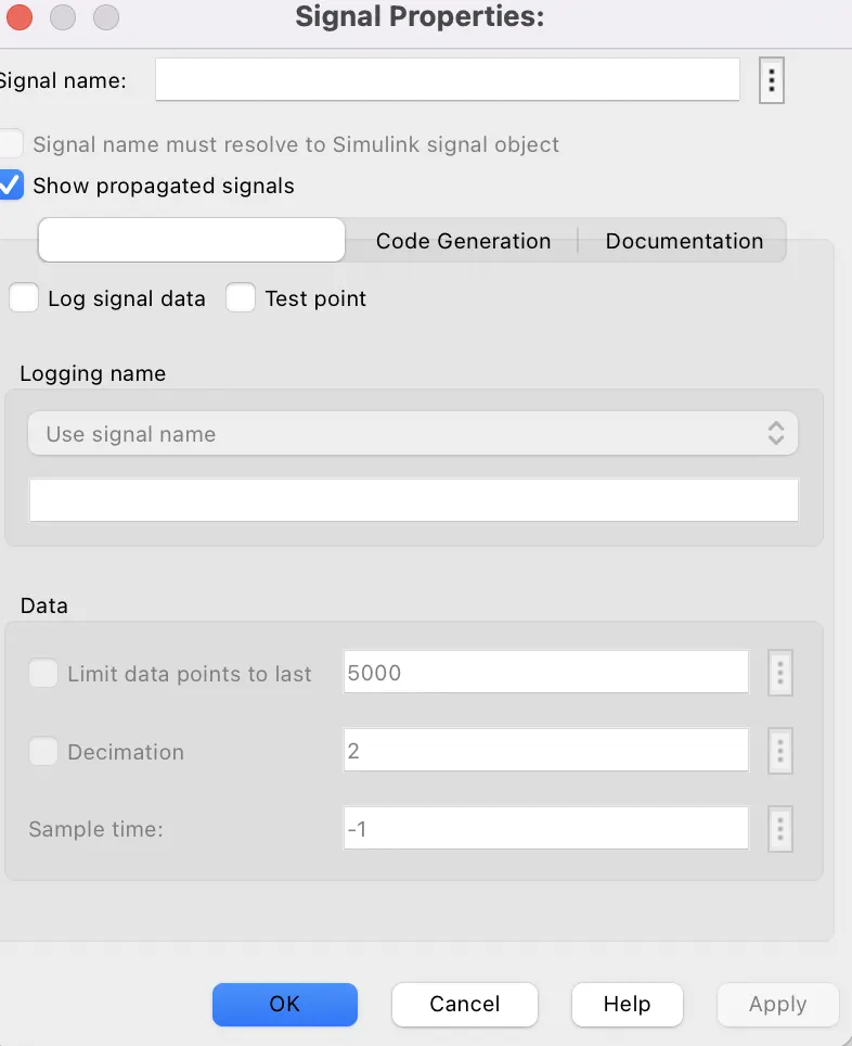

- in the above way, we have to give the properties of a signal saved in the sldd file by Signal Resolving & Signal Propagation method.
Requirement Tagging:-
- Requirement tagging is a very necessary steps in Model based developement.
- if we tag a block with some description then, we anu other person will open the block then he will cone to know the purpose of block used by click on the requirements of the block.
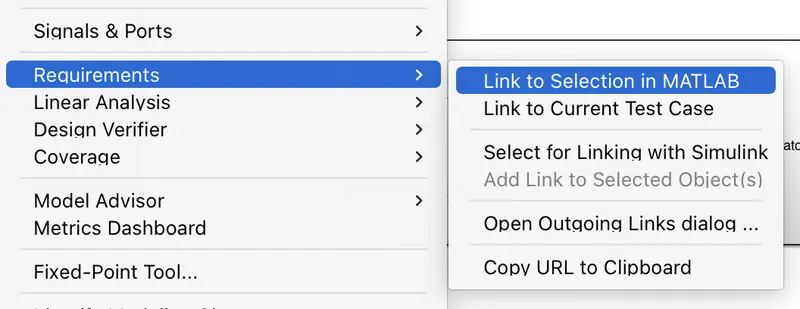
- when we right click on a subsystem then go to the Requirements option then we can see that there are some option for requirement taggich such as we can tag from the Editer or current matlab selection, we can tag from the word document selection, we acn tag from the current Test case , by using URL also we can tag a subsystem.
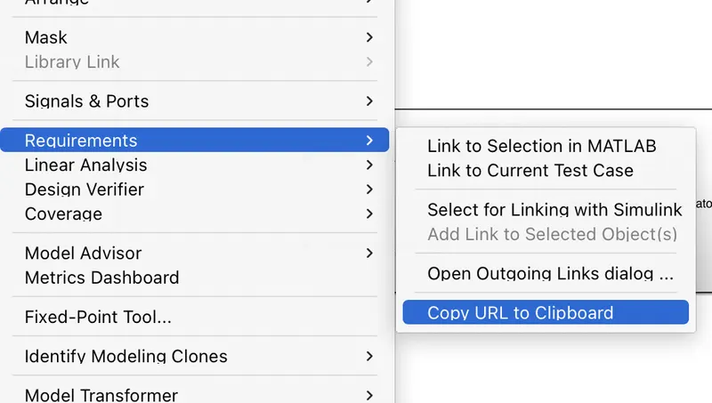
- but here i used Matlab editor to br tagged with the subsystems.
- as we know, we have 3 Main Requirements in this major project. inside the Requirement-3, there are another 6 sub-Requirements.
- so we have to describe shortly about these Reqirements in the Matlab editor such as:-



- After that we have to highlight the portion which we want to be tagged with the subsystem then right click in the subsystem, go to requirement & choose "Link To selection in MATLAB" then we can see that the highlight portion has tagged with that subsystem.
- we have to open one editor page at a time & highlight the portion which we want to tag, then go to that subsysytem & click on requirement & tag it.
- for example, We want to tag the Requirement-1 subsystem. then open the Requirement-1.m file then highligh the portion "%% Requirement-1 Lead Vehicle" then go to the Requirement-1 subsystem , then right click on that subsystem & go to requirements & click on "Link to Selection in MATLAB". then the requirement tagging for the 1st subsystem will complete.
- in this way, we have to tag the other two subsystem as per our requirements.
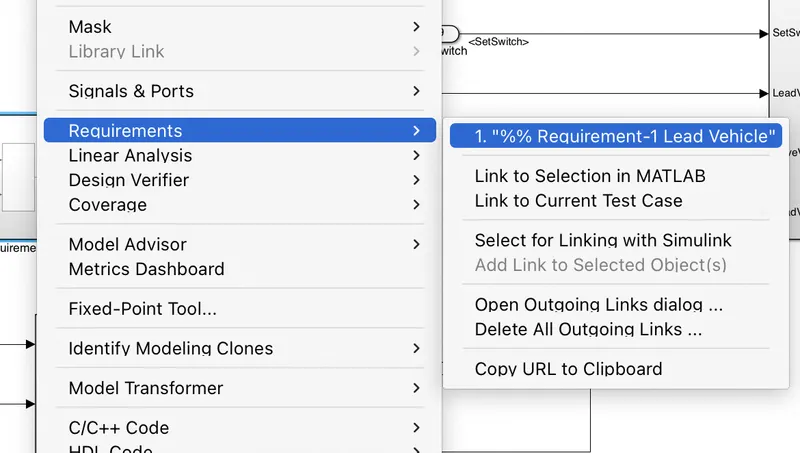
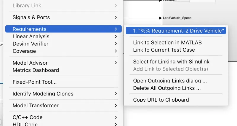
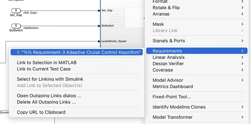
- Now the requirement tagging process is completed.
Model Advisor Check:-
- After completing the Requirement tagging process, we need to check the model by Model Advisor Check.
- By doing the model advisor check, we can able to know the total Pass check,Fail check,Warning checks & Not run checks of the model
- before going for the Model Advisor check, we have to check that whether our model simulates sucessfully without any single error.
- if there is any error during the simulation, then we have to rectify that error & then we will proceed for the model advisor check.
- then go to Modelling Tab & click on the Model advisor icon then click on the entire model to be checked.

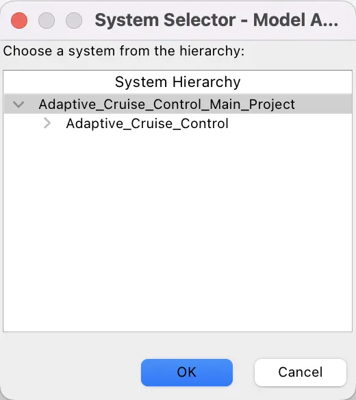
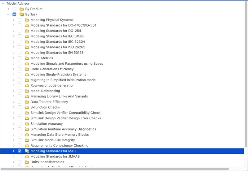
- then we can see that there are two folder to check such that By Product & By Task.
- then expand the By Task folder & select one folder with name " Modelling standards for MAAB ".
- initially there are 141 Not Run checks & other checks such as Passed,Fail & warning are 0.
- when we click on the 'Run selected checks' then we can see their are 24 warnings & 117 passed checks & fail condition is 0.
- then we have to reduce the no. of warnings as can as possible.
- so in order to do that we have to click on the warnings & select the recommonded values in the model .
- when we try 100% then we can see there are still 10-12 warnings are left which are the default setting in the model & we can't solve that one.
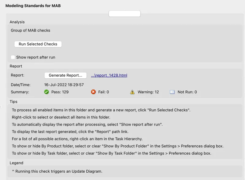
- then clickm on ' Generate Report ' & then give the name of Model advisor report then we can see that the Model advisor has geneted in the current directory path which has open the MATLAB window.
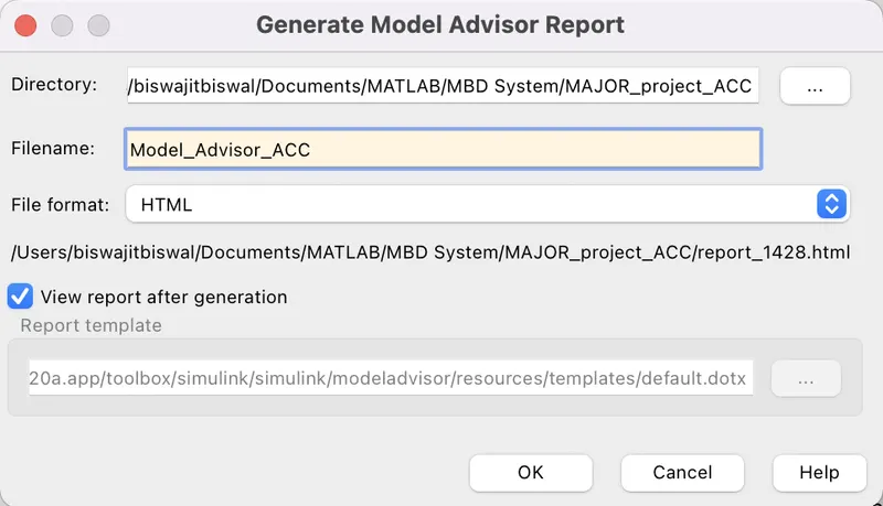
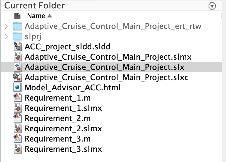
- The Model Advisor report has saved in HTML format.
Code Generation:-
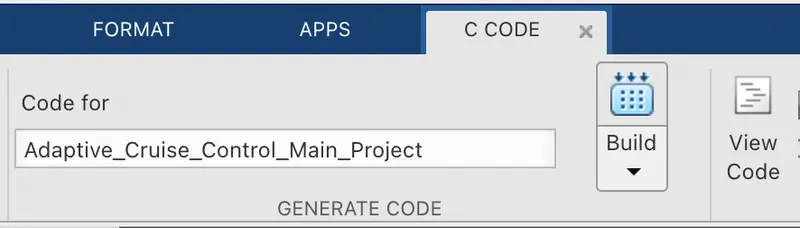
- in order to generate the code, we have to click on APPS tab then clcik on Embeded Coder.

- then go to C-code & click on Build option then we can see that c-code as follows:-
/*
* File: Adaptive_Cruise_Control_Main_Project.c
*
* Code generated for Simulink model 'Adaptive_Cruise_Control_Main_Project'.
*
* Model version : 1.20
* Simulink Coder version : 9.3 (R2020a) 18-Nov-2019
* C/C++ source code generated on : Sun Jul 17 12:36:15 2022
*
* Target selection: ert.tlc
* Embedded hardware selection: Intel->x86-64 (Windows64)
* Code generation objectives: Unspecified
* Validation result: Not run
*/
#include "Adaptive_Cruise_Control_Main_Project.h"
#include "Adaptive_Cruise_Control_Main_Project_private.h"
/* Named constants for Chart: '<S4>/ACC_Logic' */
#define Ada_IN_LeadVehicle_Not_Detected ((uint8_T)3U)
#define Adaptive_Cr_IN_ACC_STANDBY_MODE ((uint8_T)3U)
#define Adaptive_Cru_IN_NO_ACTIVE_CHILD ((uint8_T)0U)
#define Adaptive_Cruise_IN_ACC_OFF_MODE ((uint8_T)1U)
#define Adaptive_Cruise__IN_ACC_ON_MODE ((uint8_T)2U)
#define IN_LeadVehicle_Detected_Follow ((uint8_T)1U)
#define IN_LeadVehicle_Detected_Resume ((uint8_T)2U)
#define IN_LeadVehicle_Not_Detected_Res ((uint8_T)4U)
#define IN_LeadVehicle_Speed_equal_Set_ ((uint8_T)5U)
#define IN_LeadVehicle_Speed_lessthan_S ((uint8_T)6U)
/* Exported data definition */
/* Definition for custom storage class: ExportToFile */
uint8_T Acceleration_Mode; /* '<S4>/ACC_Logic' */
uint8_T DriveVehicle_Speed; /* '<S3>/Add1' */
uint8_T LeadVehicle_Detected; /* '<S3>/Signal Conversion' */
uint8_T LeadVehicle_Speed; /* '<S2>/Add' */
/* Block states (default storage) */
DW_Adaptive_Cruise_Control_Ma_T Adaptive_Cruise_Control_Main_DW;
/* Real-time model */
RT_MODEL_Adaptive_Cruise_Cont_T Adaptive_Cruise_Control_Main_M_;
RT_MODEL_Adaptive_Cruise_Cont_T *const Adaptive_Cruise_Control_Main_M =
&Adaptive_Cruise_Control_Main_M_;
/* Forward declaration for local functions */
static void Adaptive_Cruise_Con_ACC_ON_MODE(void);
real_T rt_roundd_snf(real_T u)
{
real_T y;
if (fabs(u) < 4.503599627370496E+15) {
if (u >= 0.5) {
y = floor(u + 0.5);
} else if (u > -0.5) {
y = u * 0.0;
} else {
y = ceil(u - 0.5);
}
} else {
y = u;
}
return y;
}
/* Function for Chart: '<S4>/ACC_Logic' */
static void Adaptive_Cruise_Con_ACC_ON_MODE(void)
{
int32_T tmp;
int32_T tmp_0;
uint8_T tmp_1;
uint8_T tmp_2;
/* Inport: '<Root>/SetSwitch' incorporates:
* Inport: '<Root>/CruiseSwitch'
* Inport: '<Root>/Set_Gap'
* Inport: '<Root>/Set_Speed'
* Inport: '<Root>/Time_Gap'
*/
if (!SetSwitch) {
Adaptive_Cruise_Control_Main_DW.is_ACC_ON_MODE =
Adaptive_Cru_IN_NO_ACTIVE_CHILD;
Adaptive_Cruise_Control_Main_DW.is_c3_Adaptive_Cruise_Control_M =
Adaptive_Cr_IN_ACC_STANDBY_MODE;
Acceleration_Mode = 1U;
} else if (!CruiseSwitch) {
Adaptive_Cruise_Control_Main_DW.is_ACC_ON_MODE =
Adaptive_Cru_IN_NO_ACTIVE_CHILD;
Adaptive_Cruise_Control_Main_DW.is_c3_Adaptive_Cruise_Control_M =
Adaptive_Cruise_IN_ACC_OFF_MODE;
Acceleration_Mode = 0U;
} else {
switch (Adaptive_Cruise_Control_Main_DW.is_ACC_ON_MODE) {
case IN_LeadVehicle_Detected_Follow:
Acceleration_Mode = 2U;
if (LeadVehicle_Detected == 0) {
Adaptive_Cruise_Control_Main_DW.is_ACC_ON_MODE =
Ada_IN_LeadVehicle_Not_Detected;
Acceleration_Mode = 1U;
} else {
if (((LeadVehicle_Detected == 1) && (LeadVehicle_Speed < Set_Speed)) ||
(Time_Gap < Set_Gap)) {
Adaptive_Cruise_Control_Main_DW.is_ACC_ON_MODE =
IN_LeadVehicle_Speed_lessthan_S;
Acceleration_Mode = 4U;
}
}
break;
case IN_LeadVehicle_Detected_Resume:
Acceleration_Mode = 3U;
/* Inport: '<Root>/Set_Speed' incorporates:
* Inport: '<Root>/Set_Gap'
* Inport: '<Root>/Time_Gap'
*/
if ((DriveVehicle_Speed == Set_Speed) && (LeadVehicle_Speed >= Set_Speed) &&
(Time_Gap >= Set_Gap)) {
Adaptive_Cruise_Control_Main_DW.is_ACC_ON_MODE =
IN_LeadVehicle_Detected_Follow;
Acceleration_Mode = 2U;
} else if ((DriveVehicle_Speed < Set_Speed) && (LeadVehicle_Speed >
DriveVehicle_Speed) && (Time_Gap >= Set_Gap)) {
Adaptive_Cruise_Control_Main_DW.is_ACC_ON_MODE =
IN_LeadVehicle_Speed_equal_Set_;
Acceleration_Mode = 5U;
} else {
if (LeadVehicle_Detected == 0) {
Adaptive_Cruise_Control_Main_DW.is_ACC_ON_MODE =
IN_LeadVehicle_Not_Detected_Res;
Acceleration_Mode = 1U;
}
}
break;
case Ada_IN_LeadVehicle_Not_Detected:
Acceleration_Mode = 1U;
/* Inport: '<Root>/Set_Speed' incorporates:
* Inport: '<Root>/Set_Gap'
* Inport: '<Root>/Time_Gap'
*/
if ((LeadVehicle_Detected == 1) && (DriveVehicle_Speed == Set_Speed) &&
(LeadVehicle_Speed >= Set_Speed) && (Time_Gap >= Set_Gap)) {
Adaptive_Cruise_Control_Main_DW.is_ACC_ON_MODE =
IN_LeadVehicle_Detected_Follow;
Acceleration_Mode = 2U;
} else {
if (((LeadVehicle_Detected == 1) && (LeadVehicle_Speed < Set_Speed)) ||
(Time_Gap < Set_Gap)) {
Adaptive_Cruise_Control_Main_DW.is_ACC_ON_MODE =
IN_LeadVehicle_Speed_lessthan_S;
Acceleration_Mode = 4U;
}
}
break;
case IN_LeadVehicle_Not_Detected_Res:
Acceleration_Mode = 1U;
break;
case IN_LeadVehicle_Speed_equal_Set_:
Acceleration_Mode = 5U;
/* Inport: '<Root>/Set_Speed' incorporates:
* Inport: '<Root>/Set_Gap'
* Inport: '<Root>/Time_Gap'
*/
if ((LeadVehicle_Detected == 0) || (DriveVehicle_Speed <= Set_Speed)) {
Adaptive_Cruise_Control_Main_DW.is_ACC_ON_MODE =
IN_LeadVehicle_Not_Detected_Res;
Acceleration_Mode = 1U;
} else if (((DriveVehicle_Speed < Set_Speed) && (LeadVehicle_Speed >
DriveVehicle_Speed)) || (Time_Gap >= Set_Gap)) {
Adaptive_Cruise_Control_Main_DW.is_ACC_ON_MODE =
IN_LeadVehicle_Detected_Resume;
Acceleration_Mode = 3U;
} else {
if (((LeadVehicle_Speed < Set_Speed) && (LeadVehicle_Speed <
DriveVehicle_Speed)) || ((int32_T)rt_roundd_snf(0.75 * (real_T)
Set_Gap) == Time_Gap)) {
Adaptive_Cruise_Control_Main_DW.is_ACC_ON_MODE =
IN_LeadVehicle_Speed_lessthan_S;
Acceleration_Mode = 4U;
}
}
break;
default:
/* case IN_LeadVehicle_Speed_lessthan_Set_Speed: */
Acceleration_Mode = 4U;
/* Inport: '<Root>/Set_Speed' */
if ((LeadVehicle_Detected == 0) && (DriveVehicle_Speed == Set_Speed)) {
Adaptive_Cruise_Control_Main_DW.is_ACC_ON_MODE =
Ada_IN_LeadVehicle_Not_Detected;
Acceleration_Mode = 1U;
} else {
tmp = (int32_T)rt_roundd_snf((real_T)LeadVehicle_Speed * 1.25);
/* Inport: '<Root>/Set_Gap' */
tmp_0 = (int32_T)rt_roundd_snf(1.25 * (real_T)Set_Gap);
if (tmp < 256) {
tmp_1 = (uint8_T)tmp;
} else {
tmp_1 = MAX_uint8_T;
}
if (tmp_0 < 256) {
tmp_2 = (uint8_T)tmp_0;
} else {
tmp_2 = MAX_uint8_T;
}
/* Inport: '<Root>/Time_Gap' incorporates:
* Inport: '<Root>/Set_Gap'
*/
if ((tmp_1 >= DriveVehicle_Speed) && ((int32_T)rt_roundd_snf((real_T)
LeadVehicle_Speed * 0.75) <= DriveVehicle_Speed) &&
(DriveVehicle_Speed < Set_Speed) && (Time_Gap <= tmp_2) && (Time_Gap
>= (int32_T)rt_roundd_snf(0.75 * (real_T)Set_Gap))) {
Adaptive_Cruise_Control_Main_DW.is_ACC_ON_MODE =
IN_LeadVehicle_Speed_equal_Set_;
Acceleration_Mode = 5U;
}
}
break;
}
}
/* End of Inport: '<Root>/SetSwitch' */
}
/* Model step function */
void Adaptive_Cruise_Control_Main_Project_step(void)
{
/* Sum: '<S2>/Add' incorporates:
* Inport: '<Root>/CameraInput_LeadVehicle'
* Inport: '<Root>/RadarInput_LeadVehicle'
*/
LeadVehicle_Speed = (uint8_T)((uint32_T)CameraInput_LeadVehicle +
RadarInput_LeadVehicle);
/* Sum: '<S3>/Add1' incorporates:
* Inport: '<Root>/CameraInput_DriveVehicle'
* Inport: '<Root>/RadarInput_DriveVehicle'
* Sum: '<S3>/Add'
* UnitDelay: '<S1>/Unit Delay'
*/
DriveVehicle_Speed = (uint8_T)((uint32_T)(uint8_T)((uint32_T)
CameraInput_DriveVehicle + Adaptive_Cruise_Control_Main_DW.UnitDelay_DSTATE)
+ RadarInput_DriveVehicle);
/* SignalConversion: '<S3>/Signal Conversion' incorporates:
* Inport: '<Root>/RadarInput_DriveVehicle'
*/
LeadVehicle_Detected = RadarInput_DriveVehicle;
/* Chart: '<S4>/ACC_Logic' incorporates:
* Inport: '<Root>/CruiseSwitch'
* Inport: '<Root>/SetSwitch'
*/
if (Adaptive_Cruise_Control_Main_DW.is_active_c3_Adaptive_Cruise_Co == 0U) {
Adaptive_Cruise_Control_Main_DW.is_active_c3_Adaptive_Cruise_Co = 1U;
Adaptive_Cruise_Control_Main_DW.is_c3_Adaptive_Cruise_Control_M =
Adaptive_Cruise_IN_ACC_OFF_MODE;
Acceleration_Mode = 0U;
} else {
switch (Adaptive_Cruise_Control_Main_DW.is_c3_Adaptive_Cruise_Control_M) {
case Adaptive_Cruise_IN_ACC_OFF_MODE:
Acceleration_Mode = 0U;
if (CruiseSwitch) {
Adaptive_Cruise_Control_Main_DW.is_c3_Adaptive_Cruise_Control_M =
Adaptive_Cr_IN_ACC_STANDBY_MODE;
Acceleration_Mode = 1U;
}
break;
case Adaptive_Cruise__IN_ACC_ON_MODE:
Adaptive_Cruise_Con_ACC_ON_MODE();
break;
default:
/* case IN_ACC_STANDBY_MODE: */
Acceleration_Mode = 1U;
if (!CruiseSwitch) {
Adaptive_Cruise_Control_Main_DW.is_c3_Adaptive_Cruise_Control_M =
Adaptive_Cruise_IN_ACC_OFF_MODE;
Acceleration_Mode = 0U;
} else {
if (SetSwitch) {
Adaptive_Cruise_Control_Main_DW.is_c3_Adaptive_Cruise_Control_M =
Adaptive_Cruise__IN_ACC_ON_MODE;
Adaptive_Cruise_Control_Main_DW.is_ACC_ON_MODE =
IN_LeadVehicle_Detected_Follow;
Acceleration_Mode = 2U;
}
}
break;
}
}
/* End of Chart: '<S4>/ACC_Logic' */
/* Update for UnitDelay: '<S1>/Unit Delay' */
Adaptive_Cruise_Control_Main_DW.UnitDelay_DSTATE = Acceleration_Mode;
}
/* Model initialize function */
void Adaptive_Cruise_Control_Main_Project_initialize(void)
{
/* (no initialization code required) */
}
/* Model terminate function */
void Adaptive_Cruise_Control_Main_Project_terminate(void)
{
/* (no terminate code required) */
}
/*
* File trailer for generated code.
*
* [EOF]
*/
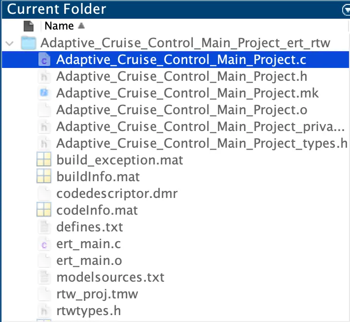
- the c-code generated (Adaptive_Cruise_Control_Main_Project.c) file is located inside Adaptive_Cruise_Control_Main_Project_ert_rtw folder.