Week - 4
EV LIVE BATCH:-21
- Implement control logic of a “washing machine” using Stateflow as per given sequence:
- If the power supply is available, the system gets activated
- If the Water supply is not available, stop the process & indicate through LED
- Soaking time should be 200s followed by Washing time of 100s.
- Then rinsing happens for next 20s & dryer runs for 50s
After all the processes have completed turn on the finished LED
Ans:- We have to implement control logic for a " Washing Machine " using stateflow.so take a simulink chart from the simulink browser.
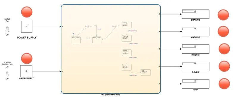
according to the question, we have to implement 7-state blocks for different states which are use to control & operate a washing machine i.e:-power supply & water supply are the most essential state block in washing machine because without these blocks we can't start a washing machine. & Soaking,washing,rinsing & dryer are the operation takes place in a washing machine. at the end there is a indicator which tell us that all process are completed.
steps:-
- 1st we take states & named it as Power supply & water supply respectiviely.
- take one transition from power supply gives condition as [x==1] & connect it with water supply, & then again one trasition from water supply with condition [y==1] & connect with soaking state which is the initial state in a washing machine procedure.
- then take another one transition from water supply as [y==0] & one transition from power supply as [x==0], then connect these two tansition with Junction so that when there is no water supply or no power supply available then there will no process takes place.
- Then, the 1st state takes place now i.e:- soaking state so we have to gave command like entry:A=1; for letting us know that soaking process is going on & give exit:A=0; for letting us know that soaking process has completed or not taking place. then take one transition from soaking state give a command as [after,(200,sec)] & connect it with washing state so that the soaking process will takes place for 200sec then it will stop & washing process will statrt.
- we have to gave command in every state i.e:- washing state,rinsing state,dryer state & end state according to soaking state. i.e:- when the process will statrt give command as entry:B/C/D/E=1; & when process will stop then exit:B/C/D/E=0; for which it will show the ON & OFF state if every state.
- according to question,Soaking time is 200sec,Washing time of 100sec,Rinsing time of 20sec & dryer runs for 50sec. so give command as [after(100,sec)],[after(20,sec)]&[after(50,sec)] to 3 different transitions & connect them from washing state to rinsing state, Rinsing state to dryer state & dryer state to end state respectively.
- now we have to take 7 lamps & connect them with Power supply,Water supply,Soaking state, washing state,rinsing state,dryer state & end state.so that the indicator lamp will glow green when the state is ON & the indicator lamp will red when state is OFF.
- give STOP TIME value as 450sec & run the model.
Run model:-
i. when the power supply is off then whole model is off.
ii. when the power supply is on but water supply is off then also there is no process takes place.
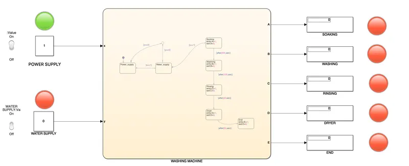
iii. when power supply off & water supply is on then also there will no process takes place.
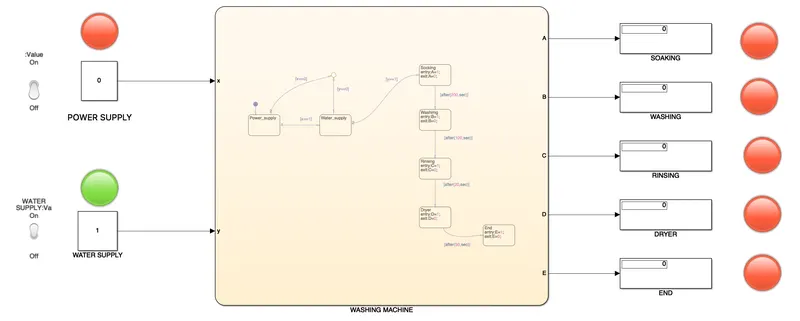
iii. when both power supply & water supply are ON ,then soaking state takes place 1st 200sec.
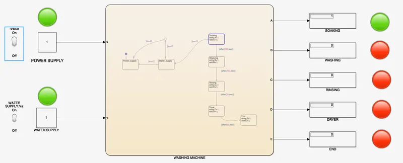
iv. after 200sec,soaking state is off & washing state is on for next 100sec & it is indicated by another indicator lamp.
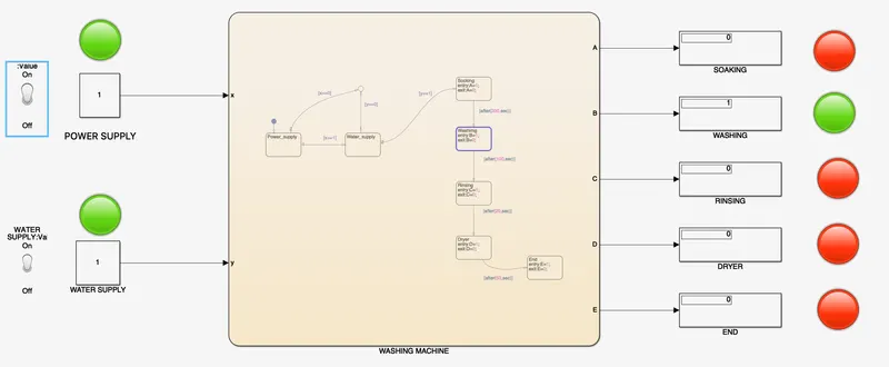
v. after 100sec,washing state if off & rinsing state is on for next 20sec & it is incated by another indicator lamp.
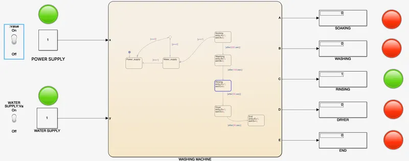
vi. after 20sec,rinsing state is off & dryer state is on for next 50sec & it is indicated by another lamp.
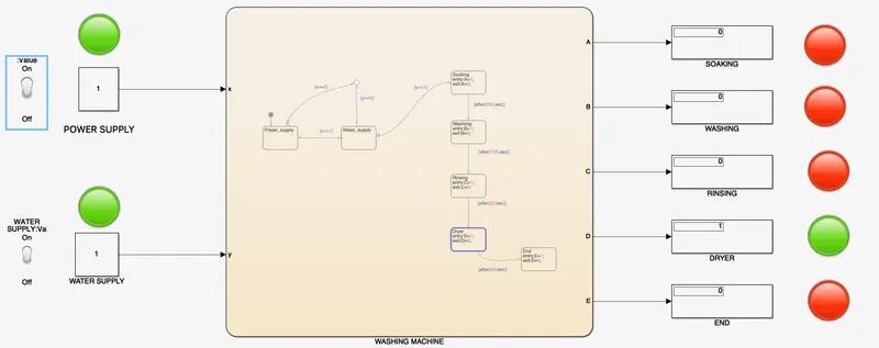
vii. after 50sec,dryer state is off & Finished indicator lamp glows which indicates that all the process are completed now.
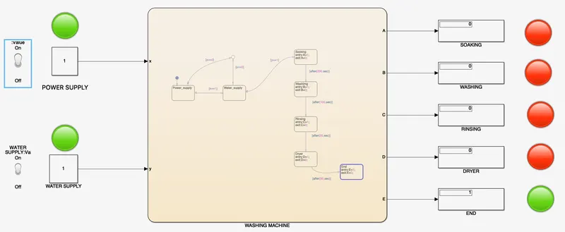 (ans)
(ans)
2. Make a Simulink chart for the “Gear shift” logic as per below conditions:
Speed Range(kmph) Gear
0 to 15 1
16 to 25 2
26 to 40 3
41 to 60 4
Above 61 5
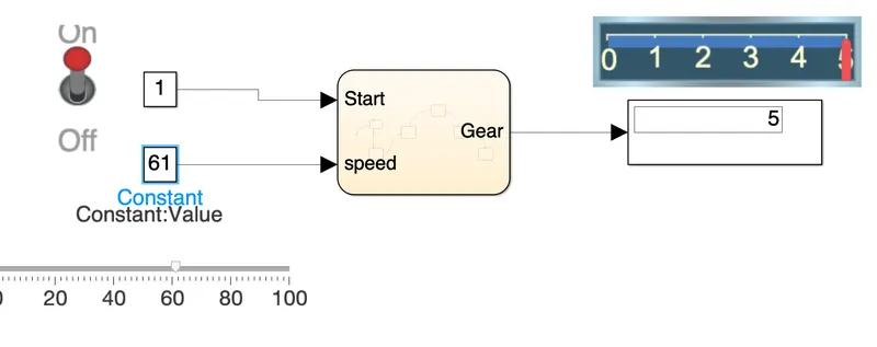
Give speed input while the simulation is running & display the gear number.
Ans:- According to the question,we have a vehicle having 5 no. of gears.there are some condtions for the gear shifting of vehicle according with the velocity.i.e:-
Speed Range(kmph) Gear
0 to 15 1
16 to 25 2
26 to 40 3
41 to 60 4
Above 61 5
!st take a chart from the simulink browser & implement it.
Steps:-
- take a defult state & named it as Start. then give command as [start==1] to one transition from this Start state & connect it with the Gear_1 state so that when the vehicle will statrt then gear shifting takes place. & give another command as [start==0] to another transition from this Start stae & connect it with junction so that when the vehicle is off condition then no gear shifting process takes place.
- Now give command to Gear_1 state as entry:Gear=1; . then take one transition from this state with command as [speed>15] & connect with Gear_2 state so that when the vehicle speed is between 0-15 kmph then the display shows 1.
- simillary according to question, we have to give commands like entry:Gear=2;,entry:Gear=3;,entry:Gear=4;,&entry:Gear=5; to Gear_2,Gear_3,Gear_4 & Gear_5 states respectively.
- simillary, take transtion fro each gear staes & give commands like [speed>25],[speed>40],[speed>60] & connect them from Gear_2 state with Gear_3 state,Gear_3 state with Gear_4 state & Gear_4 state with Gear_5 state respectively. so that when the vehicle speed is in the range from 15kmph to 25kmph then the display show gear as 2,when the vehicle speed is in between 25kmph to 40kmph then the display shows gear as 3 & when the vehicle speed is 40 kmph to 60 kmph then it shows gear as 4 & when the vehicle speed is above than 60 kmph then the display shows the gear no. is 5.
Simulation process:-
i.When the start state is off then gear shifting is not taking place.
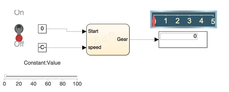
ii. when the start state is in ON mode that is vehicle is started then gear shifting process takes place such that when the vehicle speed is in the range 0 ≤ speed ≤ 15 then the display shows the gear no as 1.
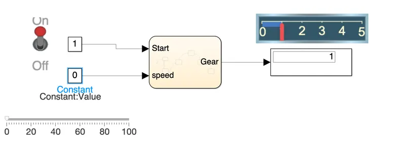
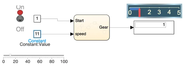
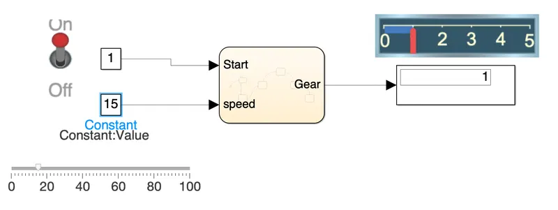
iii. when the vehicle speed is 16 ≤ speed ≤ 25 then the display shows the gear no as 2.
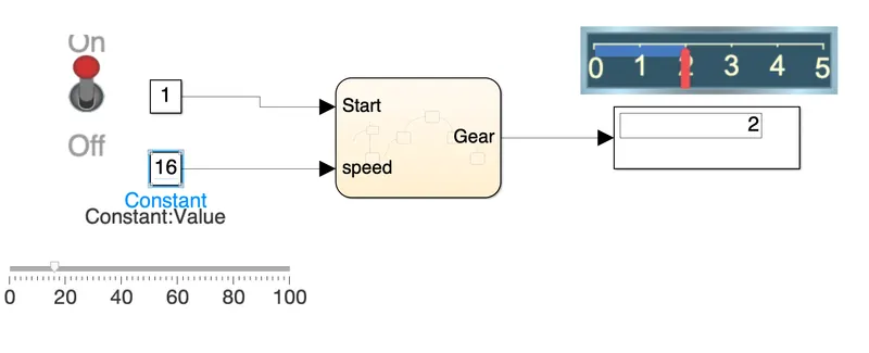
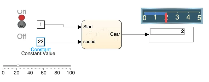
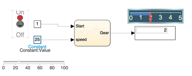
iv. when the vehicle speed is 26 ≤ speed ≤ 40 then the display shows the gear no as 3.
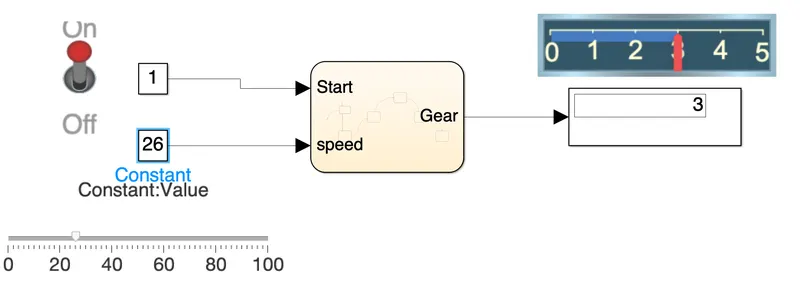
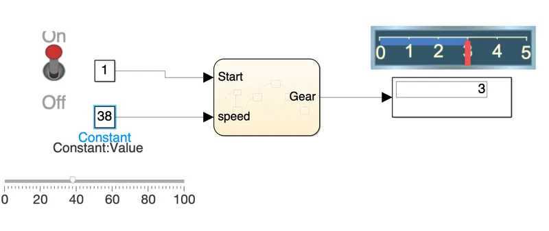
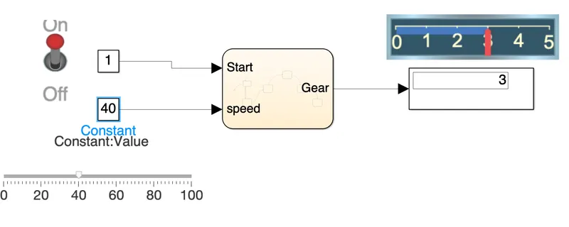
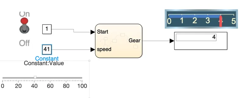
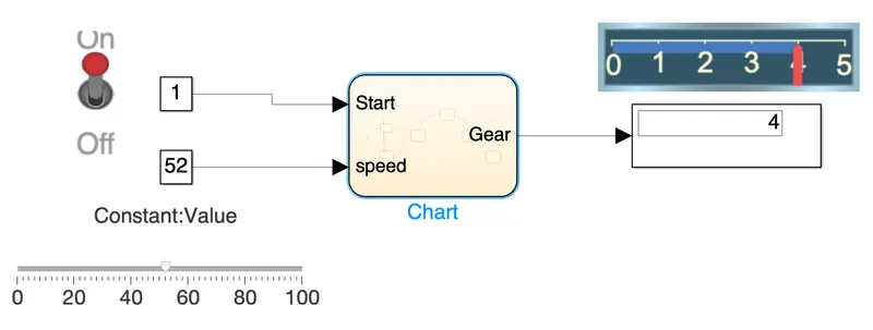
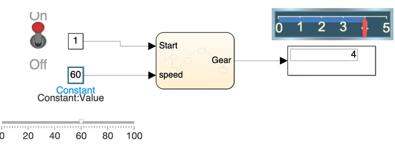
v. when the vehicle speed is in the range from 41 ≤ speed ≤ 60 then the display shows the gear no as 4.
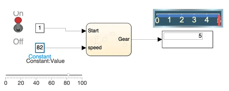
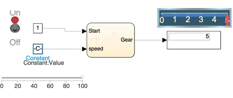
vi. when the vehicle speed is in the range from 61≤ speed then the display shows the gear no as 5.