Project 1 (Mini Project on Vehicle Direction Detection
EV LIVE BATCH:-21
Ans:-
Mini Project on Vehicle Direction Detection
Aim:-
- To gather information of a vehicle whether the vehicle is moving in right way or in right direcction by comparing the steering-wheel angle with the road sign detected by camerainput & then give that information to the driver then the driver will decide whether he has stop or to drive the vehicle i.e:- if the infomation is correct then the driver will continue the driving & if the infomarion is wrong then he has to stop the vehicle.
Objective:-
- Identifying the direction of the vehicle is one of the important & diverse features in Autonomous driving & Advanced Driver Assistance Features.
- This particular sub-feature of identifying the direction of vehicle is basically identifying the direction the vehicle is taking based on the camera input.
- Camera reads the road signs & stores into its memory with unique values for left turn, right turn & straight drive. Depending on the direction it is taking, final indication is given to the driver – as an indication if he is driving in the recommended direction or not.
Decription about steps for Modelling of the Project:-
- 1st create a new simulink blank model page & named it as Vehicle_Direction_Project_1 then save it a separate folder.
- then go to Modelling tabs & Ckick on 'Link to Data Dictionary', then create a new sldd file with name Vehicle_Direction_sldd & save it in the save folder where the ceated simulink model is present. & we have to uncheck the box while we are creating the new sldd file otherwise datas from the base workspace will link with the model blocks.
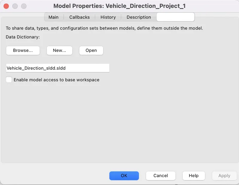
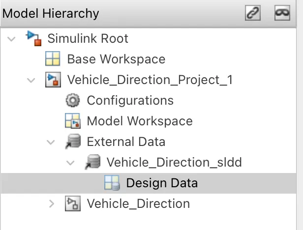
- after creating the sldd file, again click on the Modelling tab then go to the Model explorer then expand the External data below the model name then we can see there the sldd file which have created before then expand that sldd file then click on the Design Data then we have to enter values & properties of input signals, output signals & the constant parameters from the table given in the question such as:-
Signals & Calibration Data List
|
Signal / Calibration Name |
Signal Type |
Data Type |
Dimension |
Min |
Max |
Initial Value |
Units |
|
SteeringWheel_YawDegreeInput |
Input |
Int16 |
1 |
-180 |
180 |
- |
Deg |
|
CameraInput_RoadSign |
Input |
Boolean |
1 |
0 |
1 |
- |
- |
|
Vehicle_Turn_Status |
Local |
Int16 |
1 |
-180 |
180 |
- |
Deg |
|
Right_Turn_AngularLimit |
Calibration |
Int16 |
[1 1] |
-180 |
180 |
30 |
Deg |
|
Left_Turn_AngularLimit |
Calibration |
Int16 |
[1 1] |
-180 |
180 |
-120 |
Deg |
|
Straight_Drive_Steering_Angle |
Calibration |
Int16 |
[1 1] |
-180 |
180 |
0 |
Deg |
|
RightTurn_RoadSign |
Calibration |
Int16 |
[1 1] |
-180 |
180 |
30 |
|
|
LeftTurn_RoadSign |
Calibration |
Int16 |
[1 1] |
-180 |
180 |
-120 |
|
|
Straight_RoadSign |
Calibration |
Int16 |
[1 1] |
-180 |
180 |
0 |
|
|
Vehicle_Direction_Indicator |
Output |
Boolean |
1 |
0 |
1 |
- |
- |
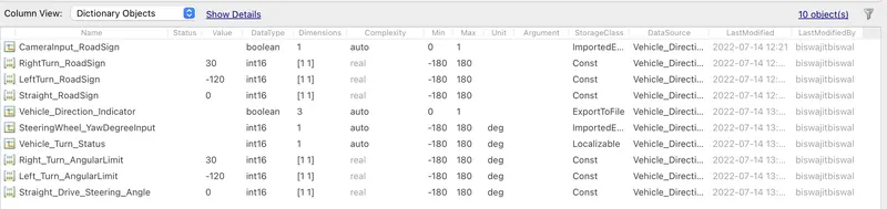
we have to enter these values & all information of all type signals inside the Design data to store inside the sldd file. such as:-
- then take a Subsystem from the simulink library browser & then open that subsystem & disconnect the inport from the outport.
- as we have two requirements which consist of two sunsystem separately (given in the question) then take another two subsystem from the simulink library browser.
Requirement-1:-
According to the question, requirement-1 has given as:-
- Steering wheel input as yaw rate (Signal name: SteeringWheel_YawDegreeInput) is the input for this system.
- This is compared against 3 angular values, one each for left turn, right turn & straight drive (Calibration Values: Right_Turn_AngularLimit, Left_Turn_AngularLimit, Straight_Drive_Steering_Angle) to say which specific direction the steering wheel is turning towards.
- Use switch blocks to compare & develop this requirement. Keep this requirement in a subsystem & output of this requirement is a local signal (Signal Name: Vehicle_Turn_Status).
- so take one subsystem & named it as Requirement_1, then take two Compare to constant blocks, 3 constant blocks & 2 switch blocks from the library browser.
- according to the Requirement-1, we have one input signal as SteeringWheel_YawDegreeInput so give the name of the inport as SteeringWheel_YawDegreeInput.
- change the 2 compare to constant blocks into (>o) & (==0) respectively.
- then give callibration values to 3 constant blocks as Right_Turn_AngularLimit, Left_Turn_AngularLimit, Straight_Drive_Steering_Angle.
- Change the "Criteria for passing the 1st input" into u2~=o of the two switch blocks.
- then connect the inport with both (>0) & (==0) blocks, then the o/p of these blocks are to be connect with control input signal of two switch blocks.
- then connect The Right_Turn_AngularLimit block with the True case port of switch 1 block & the false case port of the switch 1 block is connected with the o/p of the switch 2 block.
- then connect the Left_Turn_AngularLimit block with the true case port of switch block & false case port is connected with Straight_Drive_Steering_Angle block
- then connect the o/p of switch 1 block with the outport which is named as Vehicle_Turn_Status as given in the Requirement-1.
- now the subsystem for the Requirement_1 is completed.
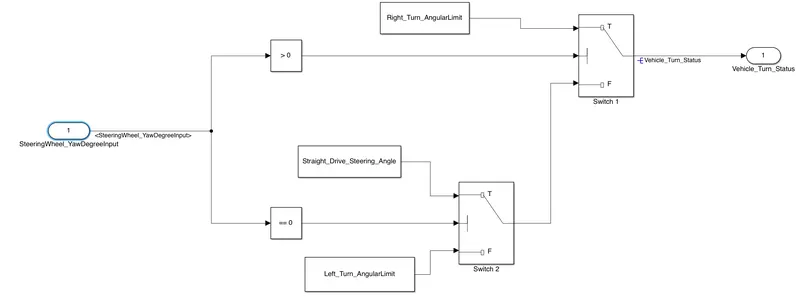
As we know that, the values for Right_Turn_AngularLimit, Left_Turn_AngularLimit, Straight_Drive_Steering_Angle blocks are 30,-120 & 0. so from the logic implemented for the Requirement-1, we can clarify that, when the input value will greater than 0 that means when the input is +ve value then (>0) block give 1 as a result, the switch 1 block will acess the true port means the Right_Turn_AngularLimit will appear as o/p result i.e:- the o/p will show 30 degree.
- when the input value will be 0 then the (==0) block give 1 then the switch 2 block will acess the true case port means the Straight_Drive_Steering_Angle will appear in the o/p result means o/p will show 0 degree.
- & when the input value is -ve then both (>0) & (==0) blocks give 0 then the false port of both switch blocks will activated, then the Left_Turn_AngularLimit will appear as the final result i.e the outport will carry -120 degree.
Requirement-2:-
According to the question, the Requirement-2 is given as:
- Keep this requirement as a separate subsystem. Inputs to this requirement are local signal from requirement 1 (Signal Name: Vehicle_Turn_Status) & an input signal from camera (Signal Name: CameraInput_RoadSign), which confirms the occurrence of a road sign.
- Signal Vehicle_Turn_Status is compared against calibration values (Calibration Values: RightTurn_RoadSign, LeftTurn_RoadSign, Straight_RoadSign), if each of them is found equal, then each of the three corresponding output is compared against the camera input signal,
- Using a logical operator block, only one among them is finally given as output signal (Signal Name: Vehicle_Direction_Indicator).
- Take 3 relationaal operators, 3 and blocks, 2 Goto blocks, 6 From blocks, 3 constant blocks, 1 Mux & ! signal conversion block from the library browser.
- as we know there are two input signals & one output signals then take another inport from thr library, then change the name of inports as Vehicle_Turn_Status & CameraInput_RoadSign & the name of outport will be Vehicle_Direction_Indicator.
- change the sign of relational operator into (==).
- connect a goto blobk with Vehicle_Turn_Status inport & named the go to block as Vehicle_Turn_Status.
- then 3 From blocks & named these as Vehicle_Turn_Status i.e whatever value present in the Vehicle_Turn_Status goto block, those are appear at the Vehicle_Turn_Status from block. then connect these from blocks with the 3 (==) operator blocks.
- then take 3 constant blocks & named these as RightTurn_RoadSign, LeftTurn_RoadSign, Straight_RoadSign. these blocks will take values from the sldd file. then connect another input terninals of 3 (==) blocks with these constant block.
- then connect the output of (==0) blocks with 3 AND blocks.
- then connect another Goto block with the CameraInput_RoadSign inport & then take the remaining 3 from blocks & named it as CameraInput_RoadSign for which whatever values comes to the CameraInput_RoadSign Goto blocks, that values will appear at CameraInput_RoadSign from blocks. then connect with the input of the AND block.
- then connect a MUX block with output terminals of these AND blocks. followed by a signal Conversion block which is used to copy the signals present in the MUX block then paste these signals to the o/p ports.
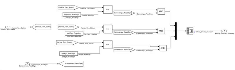
- we know the outports of the Requirement-1 will give either 30,-120 or 0. & these outport from the Requirement-1 has connected with the (==) operator.
- then from the question, we know that, values for RightTurn_RoadSign, LeftTurn_RoadSign, Straight_RoadSign are 30,-120 & 0. these blocks are connected with the 3 (==) oeprator blocks respecivelythen if the Vehicle_Turn_Status inport will give 30 then the 1st (==) operator will give 1, if the Vehicle_Turn_Status will give -120 then the 2nd (==) operator will give 1 & if the Vehicle_Turn_Status will give 0 then the 3rd (==) operator will give 1.
- as we know, these outputs from the (==) operaor has connected with AND blocks & all AND blocks are also connected with the CameraInput_RoadSign from blocks.
- here CameraInput_RoadSign is a boolean type signal that means it will either 0 or 1.
- when CameraInput_RoadSign is 1 then any one of the Outputs of AND block will bw 1 because another input to the AND block is 1 at a perticular time.
- if the CameraInput_RoadSign is 0 then the Outputs of AND blocks are 0.
- as there are 3 signals coming from the AND block we have connected a MUX block to combine these signals into 1 signal. then it will pass through the signal conversion block which is used to copy the signal from the MUX block & send to the outports.
- the outport is named as Vehicle_Direction_Indicator.
Construction of main Model:-
- we had taken a subsystem previously before creating logics for thr Requirement-1 & Requirement-2.
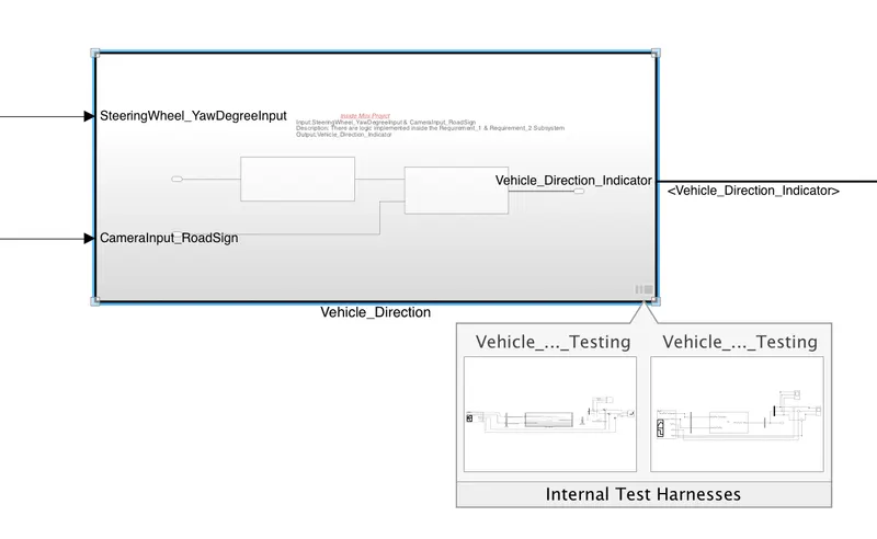
- then after completion of Requirement-1 & Requirement-2 modelling, we can see there there are 3 ports available in the subsyste to connect, 2 ports are for inputs as SteeringWheel_YawDegreeInput & CameraInput_RoadSign, & 1 port is for outport as Vehicle_Direction_Indicator.
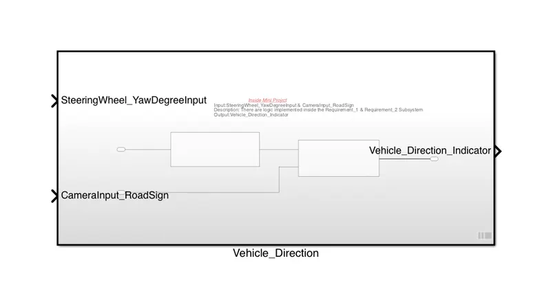
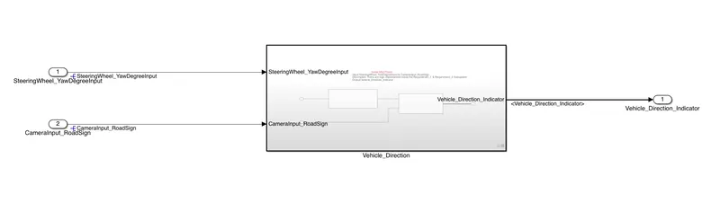
- then take two inports & 1 outports from the simulink library browser.
- then give the name of inports as SteeringWheel_YawDegreeInput & CameraInput_RoadSign & the outport as Vehicle_Direction_Indicator. & connect with the subsystem as follows.
Requirement Tagging:-
- We have to tag our subsystem wit some description properly, because when another person will open the model again, then he can understand about the construction of subsystems & he can understand the logics are implemented inside the subsystem by click on the requirement tagging.
- when we right click on a subsystem then go to the Requirements option then we can see that there are some option for requirement taggich such as we can tag from the Editer or current matlab selection, we can tag from the word document selection, we acn tag from the current Test case , by using URL also we can tag a subsystem.
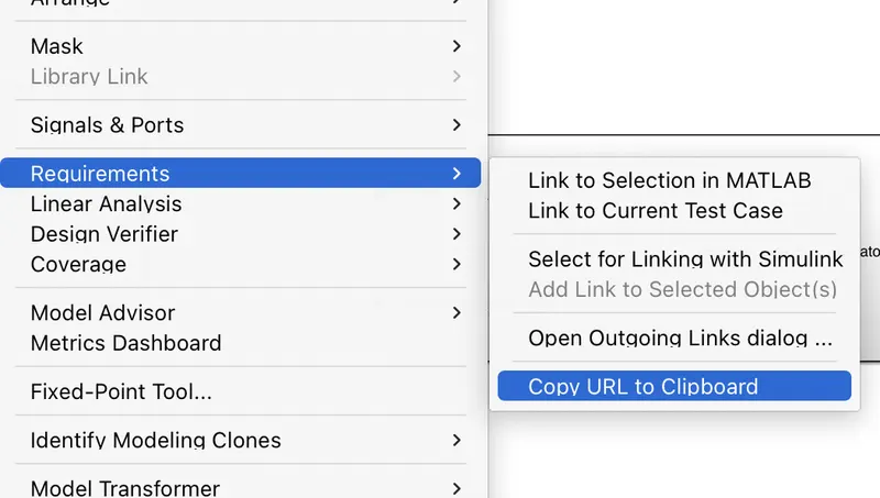
- we have to write some description about the subsystem either In word document or in Matlab Editer & we have to hilight the portion,which will be the mail heading for the subsystem such as follows:


- then after hilighting the portion, right click on the subsystem which we want to tag then go to requirement then click on "Link to Selection in MATLAB' such as
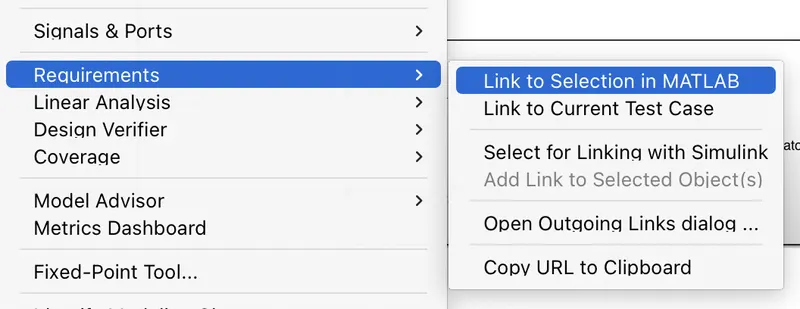
- then the tagging for the subsystem is done. if we want to see the requirement tagging for that subsystem, then again right clcik on the subsystem, go to Requirements then wecan see the subsystem is tagged by the top seleted portion.
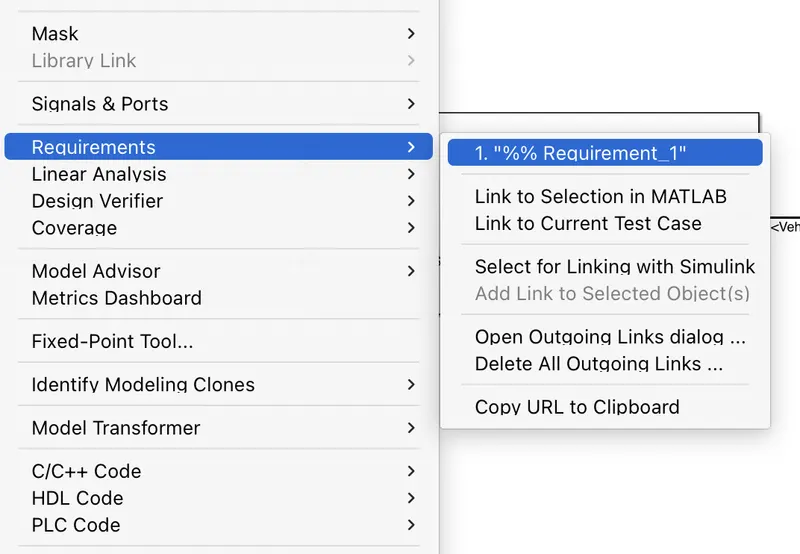
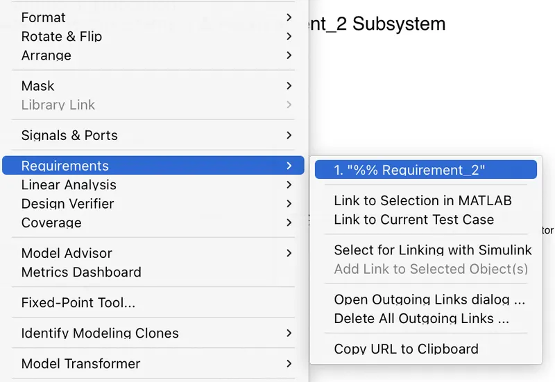
- now the Requirement Tagging Process is done completely.
Model Advisor Test & Test Harness for Mini Project:-
- Before Model Advisor test & Test Harness we have to change some settings.
- Go to modelling tab then click on the Model Setting & Change the solver as Fixed Step Solver & descrete(no contineous state) & keep the sample time as 0.01sec.
- then goto Code Generation, change the system target file as Embeded Coder. then click on Apply & ok.
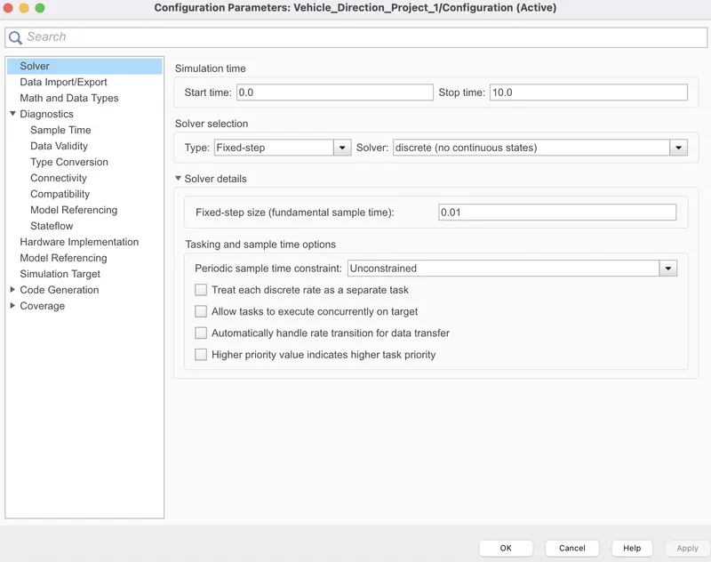
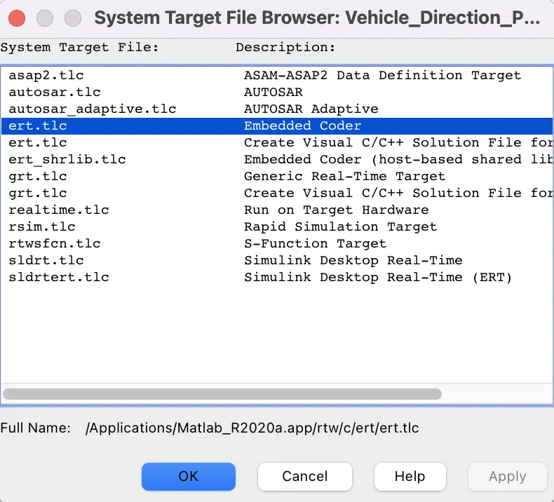
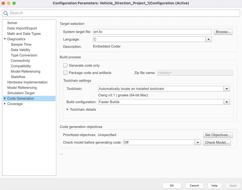
- then before going for Model advisor, Our model should simulate without any single error.
- then go to the modelling & click on the Model advisor icon, & then select the entire mofel for testing through thr Model Advisor.
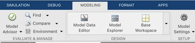
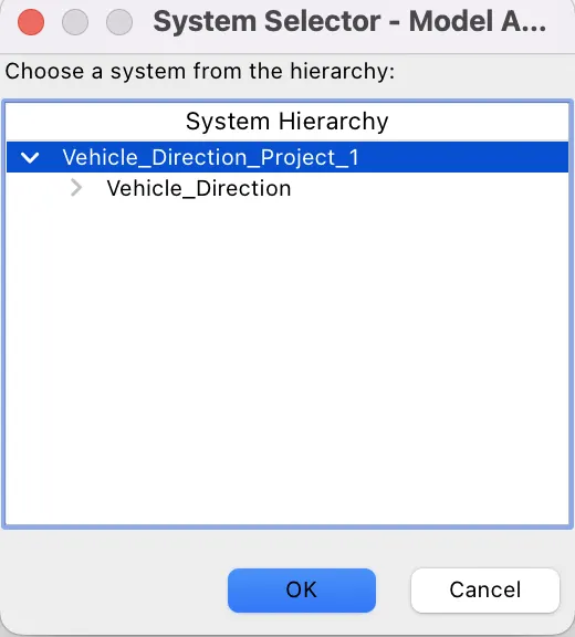
- then a Model advisor page will open & then there are two folders such as By Product & By Task.
- uncheck the By Product folder & expand the By Task folder & click on the Modelling standards for MAB folder then click on "Run Selected Checks".
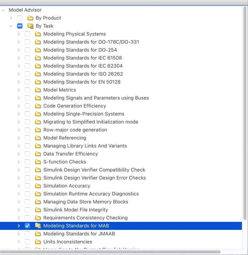
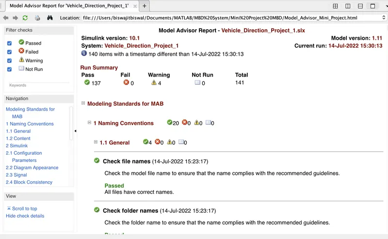
- Initially we can see there are 141 checks that we have run run.
- then after checking there will showing np of passed checks, No of failed checks, No of Warnings & no of Not run checks as follows:-
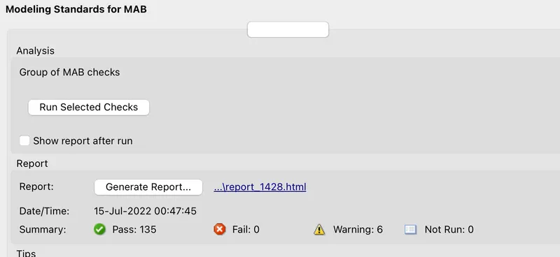
- it is very important that there should not any single failed condition.
- after running may be there are more warnings such as 10 or 12 but we have to reduce the no, of warnings as can as possible may be 3 or 4 warnings may consider.
- then we have to click on that Generate report & then we have to give the fine name & then click on ok.
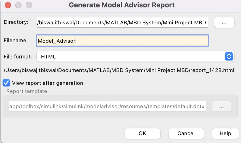
- then the Model Advisor will geneted & saved in the current directtory opened in the MATLAB window & the file format is html.
- when we that html fine then we can see the no of passed, fail,warning & Not Run checks for thr model.
Test Harness Testing of the Model:-
We know there are 3 types of test harness testing methods to test a model & approved as per the result coming from the testing such as
- Model-In-The-Loop testing (MIL)
- Software-In-The-Loop testing (SIL)
- Hardware-In-The-Loop testing (HIL)
But in the simulink, we can able to test the Model-In-The-Loop testing & Software-In-The-Loop testing of a model.
(1) Model-In-The-Loop (MIL) Testing:-
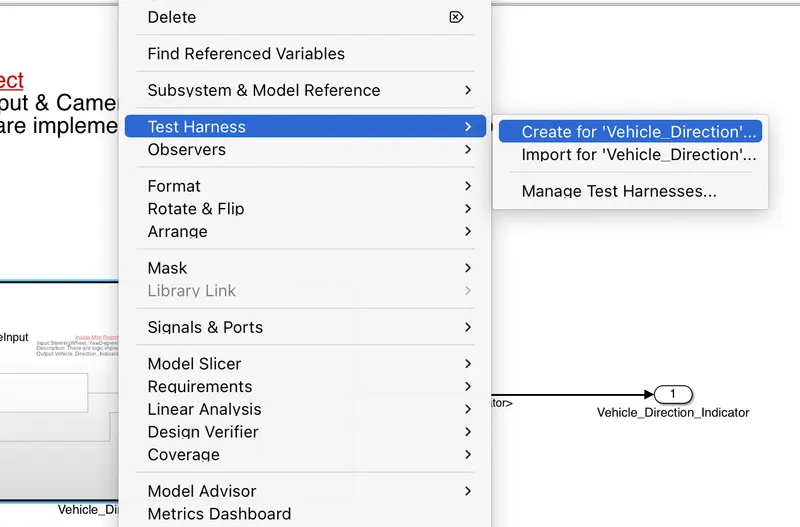
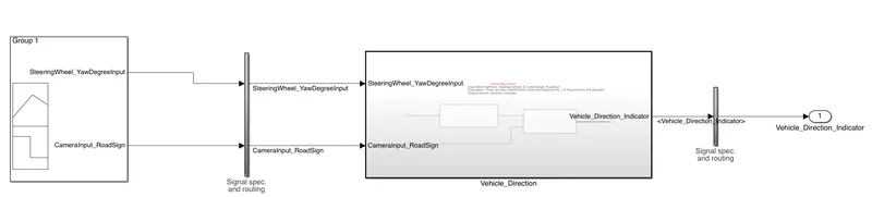
- In order to do the MIL testing, 1st right click on the Vehicle_Direction subsystem, then go to Test Harness & click on the 'Create for subsystem'
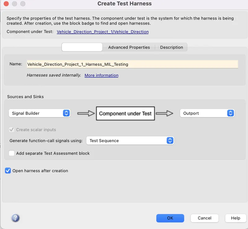
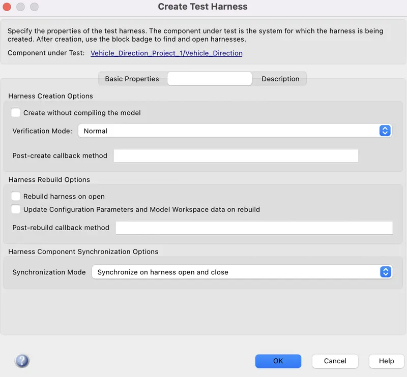
- then anew page will open & then choose the source as Signal builder & sink as Outports, then give a name for the test harness & then go to Advanced Properties, choose the verification mode as Normal which is for MIL test harness testing, then click ok.
- then new simulink page will open for thr MIL test harness, & the model looks like as follows:-
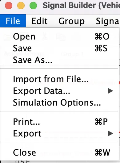
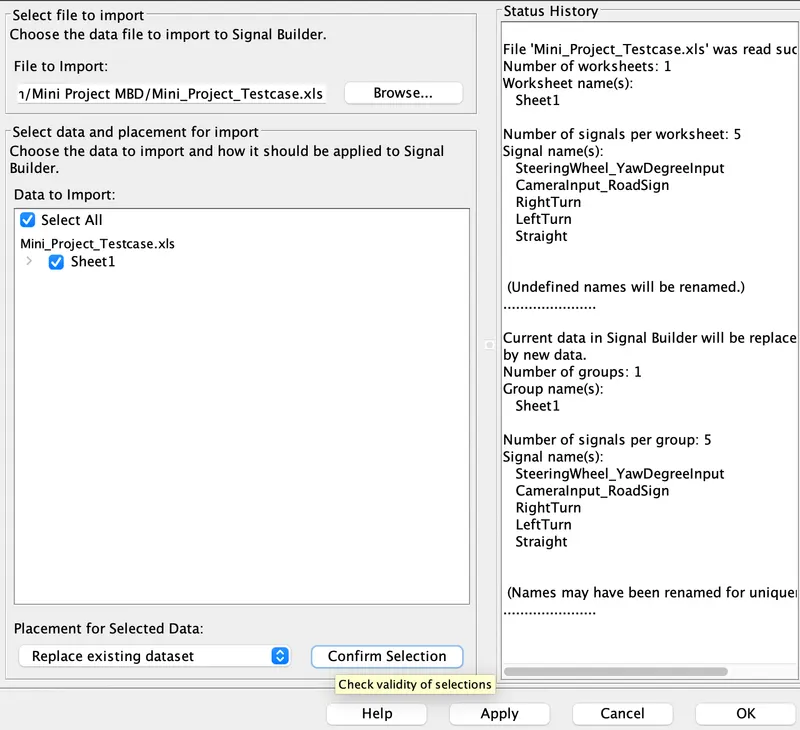
- Then click on the signal builder block,click on the file then click on the Imort from file then browse the excel file in which we have created before to imort signal as per our requirement.
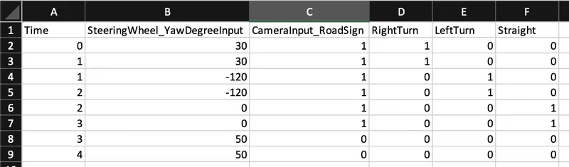
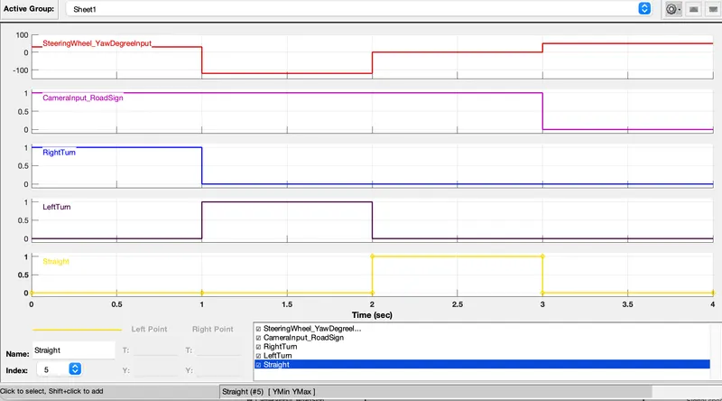
- From the excel sheet & the signal builder block signal, we cleared that, when the SteeringWheel_YawDegreeInput is 30 then the RightTurn is 1 & the LeftTurn,Straight commands are 0.
- when SteeringWheel_YawDegreeInput is -120 then LeftTurn is 1 & other two signal commands are 0.
- when SteeringWheel_YawDegreeInput is0, then the Straight command is 1 & the other two commands are 0.
- but when SteeringWheel_YawDegreeInput is 50, at that time, the Camera input does detect any road sign means 0 so, all signal commands are 0.
- after imporing signal from the excel sheet into the signal builder block then the model looks like as follows:-
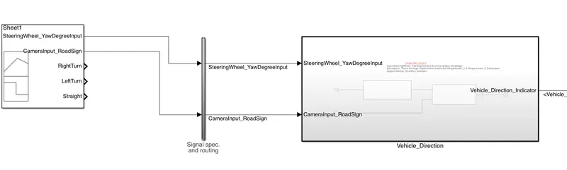
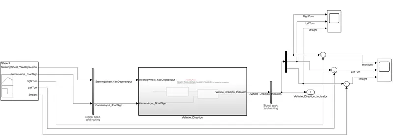
- Here take 1 Demux block, 3 sum blocks & two scopes from the library browser.
- connect the i.p of the Demux with the output signal line coming from the signal specification & Routing block.
- then change the list of signs as +,- in all sum blocks.
- choose the no of o/p port as 3 of the Demux block.
- then connect the o/p of the Demux with the +ve terminal of sum blocks & connect the -ve terminals of sum block with RightTurn,LeftTurn & Straight of the signal builder block. this connection has done to check the difference between the i/p signals & the o/p signals.
- then again change the no of inport as 3 for another scope & then connect these inports with the o/p signal coming from the Demux block.
Result of the MIL Testing:-
- as we take the time range in the signal builder from 0sec to 4sec, so when we run the model for 4sec, then we got a scope result of o/p signals as follows
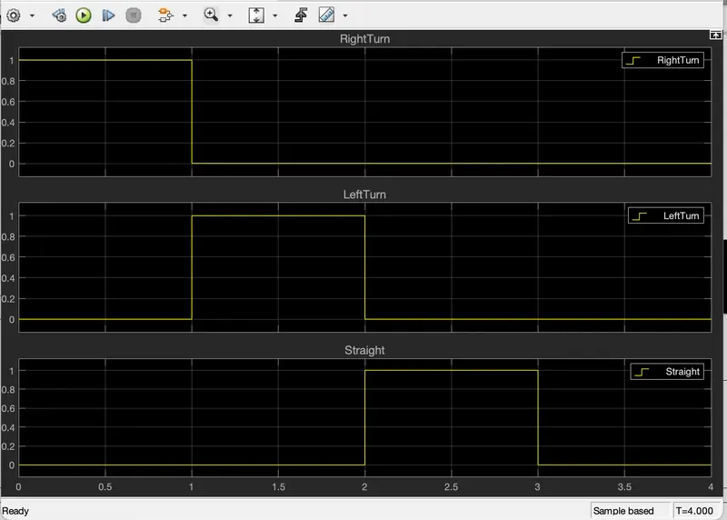
when we analyse the above scope,we can see that there are 3 signals coming from the Demux block such as RightTurn,LeftTurn & Straight. for 0sec to 1 sec,i.e when SteeringWheel_YawDegreeInput is 30, the RightTurn is 1 & the other two signals are 0, & when from 1sec to 2sec,i.e:- when SteeringWheel_YawDegreeInput is-120, the LeftTurn is 1 & other two signals are 0 then from 2sec to 3sec,i.e:- whenSteeringWheel_YawDegreeInput is 0, the Straight signal is 1 & the other are 0. but from3sec to 4sec,i.e:- when SteeringWheel_YawDegreeInput is 50, all signals are 0.
this signal excatly match wit the signal builder blocks such as
- When we analse the scope connected with the sum blocks, then we found
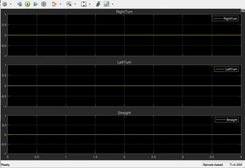
from the graph, we can see that all signals such as RightTurn,LeftTurn & Straight signals are 0, that menas the difference between the output signal & the input signal is 0.which states that the output signals are same with the inputs signals. which is the main motive of our model.
so the MIL testing for the model is sucessfully completed & gives 100% result.
(2) Software-In-The-Loop Testing (SIL)
- Before creating test harness for thr SIL testing,we have to change the subsystem as atomic in nature. in order to do that, right click on the subsystem, go to the block parameters, then click on 'Treat as Atomic Unit' then give the sample time as 0.01sec then ok.
-
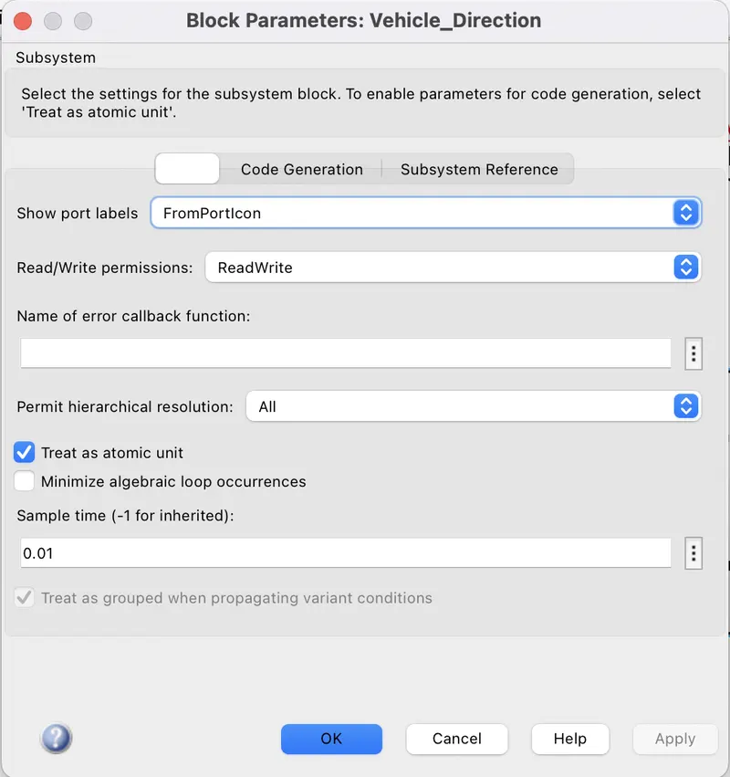
- then right click on the subsystem, then go to test harness then click on the 'Create for Subsystem'.
- then a new page will open, then select the source as Signal builder & the sink as outport, then give a name for test harness. then goto advanced properties & choose the verification mode as Software-In-The-Loop (SIL) for the test harness of a SIL testing. then click on ok.
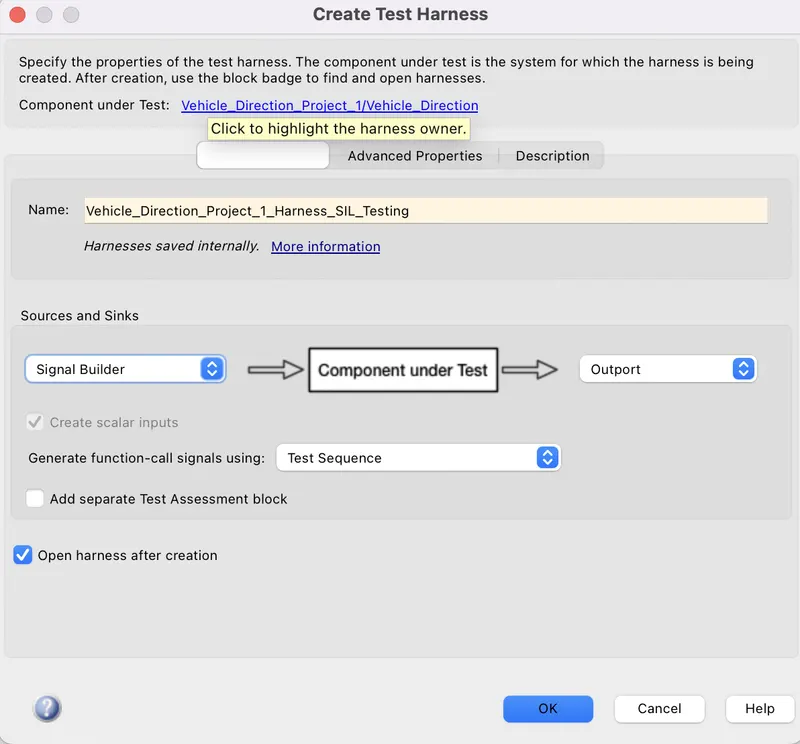
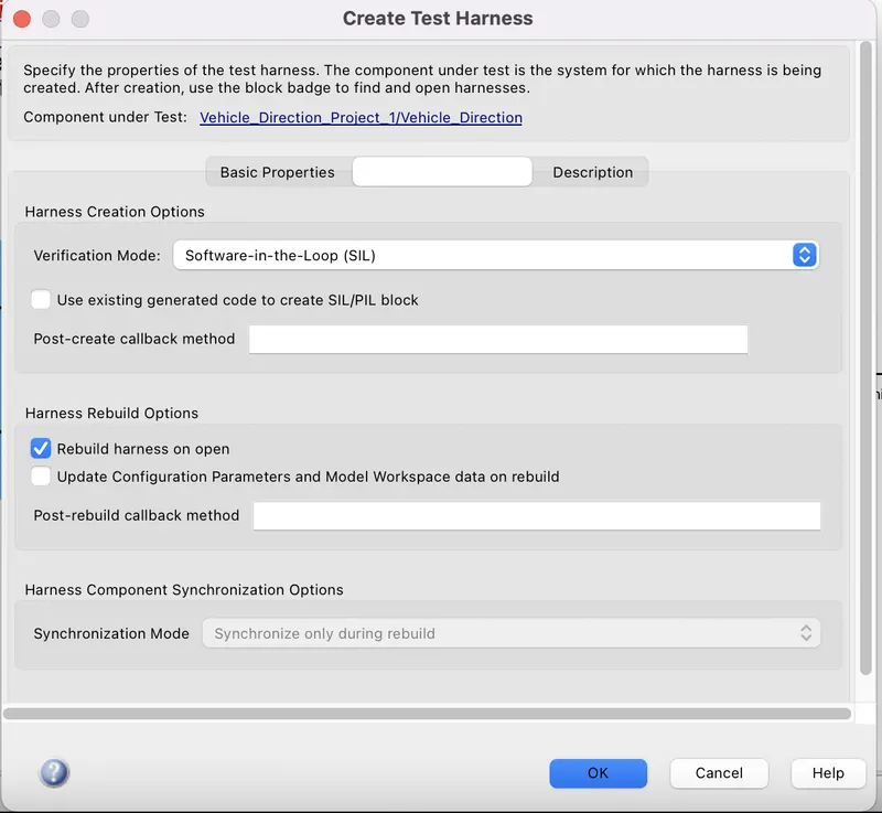
- then a new simylink file containing the s-function block will open for the SIL testing sun as:-
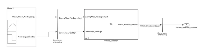
- then click on the signal builder block, go to file then click on the import from file then browse the excel file containg the data for creating signals in the signal builder as per our requirement.
- when we import the signal from the excel sheet, then it lokks like as:-
- after creating the signals in the signal builder block, then the model looks like
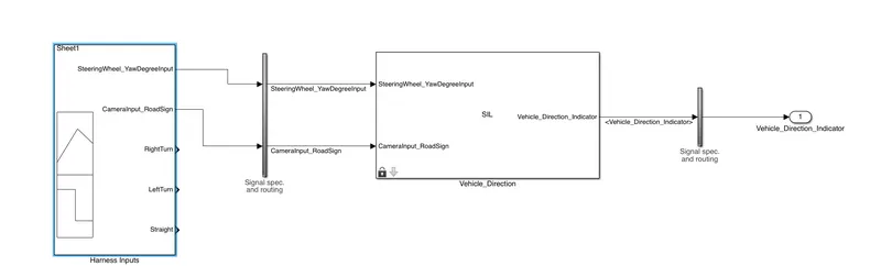
- Here we can see that there are 5 signals in the signal builder such as SteeringWheel_YawDegreeInput,CameraInput_RoadSign,RightTurn,LeftTurn & Straight signals.
- then take 3 sum blocks, 1 Demux block, & 2 scope blocks from the simulink library browser.
- then connect every block same as the connection has done in the MIL testing. then we got our final model such as:-
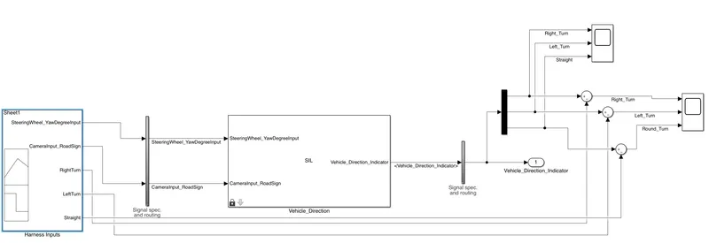
Result of the SIL testing test harness:-
- when we run the model for 4 sec, then we found two scope results such as
when we analyse the above scope,we can see that there are 3 signals coming from the Demux block such as RightTurn,LeftTurn & Straight. for 0sec to 1 sec,i.e when SteeringWheel_YawDegreeInput is 30, the RightTurn is 1 & the other two signals are 0, & when from 1sec to 2sec,i.e:- when SteeringWheel_YawDegreeInput is-120, the LeftTurn is 1 & other two signals are 0 then from 2sec to 3sec,i.e:- whenSteeringWheel_YawDegreeInput is 0, the Straight signal is 1 & the other are 0. but from3sec to 4sec,i.e:- when SteeringWheel_YawDegreeInput is 50, all signals are 0.
this signal excatly match wit the signal builder blocks such as
- When we analse the scope connected with the sum blocks, then we found
-
from the graph, we can see that all signals such as RightTurn,LeftTurn & Straight signals are 0, that menas the difference between the output signal & the input signal is 0.which states that the output signals are same with the inputs signals. which is the main motive of our model.
- this states that the model has passed the SIL testing sucessfully.
Note:-
- when we create test harness for the SIL testing then, there is a file as "Vehicle_Direction_ert_rtw" is generated in the same folder where we are working on the Mini project. this file consisting of (.c) file,(.h) file etc. these files are containg the generated code Of the whole model.
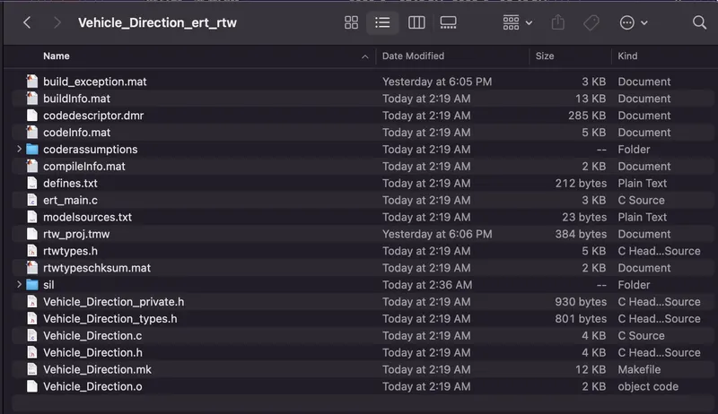
- after completion of the SIL testing, we have to click on the APPS tab, then click on the Embeded Coder, then click on Built icon then we can see the generated code of the model there.

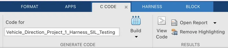
- The c-code for the Mini-Project is as follows:-
/*
* File: Vehicle_Direction.c
*
* Code generated for Simulink model 'Vehicle_Direction'.
*
* Model version : 1.14
* Simulink Coder version : 9.3 (R2020a) 18-Nov-2019
* C/C++ source code generated on : Fri Jul 15 02:19:25 2022
*
* Target selection: ert.tlc
* Embedded hardware selection: Intel->x86-64 (Mac OS X)
* Code generation objectives: Unspecified
* Validation result: Not run
*/
#include "Vehicle_Direction.h"
#include "Vehicle_Direction_private.h"
/* Exported data definition */
/* Definition for custom storage class: ExportToFile */
boolean_T Vehicle_Direction_Indicator[3];/* '<S2>/Signal Conversion' */
/* Const memory section */
/* Definition for custom storage class: Const */
const int16_T LeftTurn_RoadSign = -120;
/* Referenced by: '<S2>/RightTurn_RoadSign' */
const int16_T Left_Turn_AngularLimit = -120;/* Referenced by: '<S3>/Constant2' */
const int16_T RightTurn_RoadSign = 30;
/* Referenced by: '<S2>/LeftTurn_RoadSign' */
const int16_T Right_Turn_AngularLimit = 30;/* Referenced by: '<S3>/Constant' */
const int16_T Straight_Drive_Steering_Angle = 0;/* Referenced by: '<S3>/Constant1' */
const int16_T Straight_RoadSign = 0;
/* Referenced by: '<S2>/Straight_RoadSign' */
/* Real-time model */
RT_MODEL_Vehicle_Direction_T Vehicle_Direction_M_;
RT_MODEL_Vehicle_Direction_T *const Vehicle_Direction_M = &Vehicle_Direction_M_;
/* Model step function */
void Vehicle_Direction_step(void)
{
/* local block i/o variables */
int16_T Vehicle_Turn_Status;
/* Outputs for Atomic SubSystem: '<Root>/Vehicle_Direction' */
/* Switch: '<S3>/Switch 1' incorporates:
* Constant: '<S3>/Constant'
* Constant: '<S3>/Constant2'
* Constant: '<S4>/Constant'
* Constant: '<S5>/Constant'
* Inport: '<Root>/SteeringWheel_YawDegreeInput'
* RelationalOperator: '<S4>/Compare'
* RelationalOperator: '<S5>/Compare'
* Switch: '<S3>/Switch 2'
*/
if (SteeringWheel_YawDegreeInput > 0) {
Vehicle_Turn_Status = Right_Turn_AngularLimit;
} else if (SteeringWheel_YawDegreeInput == 0) {
/* Switch: '<S3>/Switch 2' incorporates:
* Constant: '<S3>/Constant1'
*/
Vehicle_Turn_Status = Straight_Drive_Steering_Angle;
} else {
Vehicle_Turn_Status = Left_Turn_AngularLimit;
}
/* End of Switch: '<S3>/Switch 1' */
/* SignalConversion: '<S2>/Signal Conversion' incorporates:
* Constant: '<S2>/LeftTurn_RoadSign'
* Constant: '<S2>/RightTurn_RoadSign'
* Constant: '<S2>/Straight_RoadSign'
* Inport: '<Root>/CameraInput_RoadSign'
* Logic: '<S2>/AND'
* Logic: '<S2>/AND1'
* Logic: '<S2>/AND2'
* RelationalOperator: '<S2>/Relational Operator'
* RelationalOperator: '<S2>/Relational Operator1'
* RelationalOperator: '<S2>/Relational Operator2'
*/
Vehicle_Direction_Indicator[0] = ((Vehicle_Turn_Status == RightTurn_RoadSign) &&
CameraInput_RoadSign);
Vehicle_Direction_Indicator[1] = ((Vehicle_Turn_Status == LeftTurn_RoadSign) &&
CameraInput_RoadSign);
Vehicle_Direction_Indicator[2] = ((Vehicle_Turn_Status == Straight_RoadSign) &&
CameraInput_RoadSign);
/* End of Outputs for SubSystem: '<Root>/Vehicle_Direction' */
}
/* Model initialize function */
void Vehicle_Direction_initialize(void)
{
/* (no initialization code required) */
}
/* Model terminate function */
void Vehicle_Direction_terminate(void)
{
/* (no terminate code required) */
}
/*
* File trailer for generated code.
*
* [EOF]
*/
- we can see the two test harness by clicking the small symbol available at the buttom of the right side of the main subsystem such as:-