Project 2 Thermal modeling of battery pack
For a 10 cell series lithium ion battery model, simulate the thermal effects and compare life cycle performance at various temperatures, charge & discharge rates using MATLAB.
Thermal management system:
In this section, a brief overview of the major thermal issues that necessitate thermal management of lithium-ion batteries is presented. These include capacity/power fade, thermal runaway, electrical imbalance among multiple cells in a battery pack, and low temperature performance
The increase of the internal temperature can lead to the drop of the battery resistance, and in turn affect the heat generation. The change of resistance will also affect the battery power.
Thermal runaway of the lithium-ion battery initiates an unstoppable chain reaction. The temperature rises rapidly within milliseconds and the energy stored in the battery is suddenly released.
The main aim of the BTMS is to regulate the temperature of the cells of the battery and thereby increase the lifespan of the battery. There are two main types of BTMS: active systems and passive systems. The active system mainly depends on forced circulation of a specific coolant such as water or air.
Thermal issues in lithium ion battery:
The performance, life, and safety of lithium-ion batteries are all affected by their operation and/or storage temperatures. In this section, a brief overview of the major thermal issues that necessitate thermal management of lithium-ion batteries is presented. These include capacity/power fade, thermal runaway, electrical imbalance among multiple cells in a battery pack, and low temperature performance. Emphasis is placed on the impact of temperature on each of these phenomena. Furthermore, coupling between electrochemical reactions and transport phenomena, which in turn affects the temperature, is discussed. Studies in each area are highlighted and discussed so that critical research gaps in thermal management strategies can be identified.
Self-discharge
The studies discussed above all investigated the amount of recoverable energy after storing or cycling lithium-ion batteries at a variety of temperatures. However, batteries can reversibly self-discharge, thus lowering the capacity retained. For example, as explained by Aurbach, fully charged graphite electrodes are strong reducing agents and the solid electrolyte interphase (SEI) formed on the surface does not completely passivate them. Hence, electrons and lithium-ions can simultaneously pass through the surface film, increasing the potential of the negative electrode. Increased temperatures can cause the surface species to dissolve, thus increasing the electronic conductivity and, in turn, the rate of self-discharge. Whereas self-discharge is not expected to be important for lithium-ion batteries used in electric vehicles, it can be significant for other applications where the cell remains unused for a considerable period of time in hot ambient conditions.
The capacity retention appears to decrease linearly throughout the test period. Hence, if stored at 60c, the capacity reduces only at a rate of 0.44% per day, which is not significant for HEVs or EVs that are driven frequently. Of course, this rate is dependent on the cell chemistry, but proper electrolyte/electrode combinations should alleviate this relatively small concern.
heat generation and thermal modeling:
Because lithium-ion battery performance is strongly linked to temperature, it is important to understand how heat is generated and dissipated inside a battery. Heat generation inside batteries is a complex process that requires understanding of how the electrochemical reaction rates change with time and temperature and how current is distributed within larger batteries.
Many investigators have studied thermal heat dissipation characteristics inside both single-cell batteries and multicell battery packs using a variety of assumptions applied to both simple 1D models with uniform heat generation and detailed 3D coupled electrochemical–thermal models. Some investigators have attempted to measure battery heat generation rates using both commercially available and custom-built calorimeters. The use of experimental data is critical to understand the order of magnitude and pattern of the variety of mechanisms that cause batteries to generate heat.
- Proper Storage Temperature. One of the simplest ways to prevent thermal runaway is to store batteries at safe temperatures
- Proper Ventilation
- Replace Old Batteries
- Don't Overcharge
Batteries thermal management system
The basic types of BTMS are listed below.
1. Air cooling
2. Liquid cooling
3. Direct refrigerant cooling
4. Phase change material cooling
5. Thermoelectric cooling
6. Heat pipe cooling
simulink model:
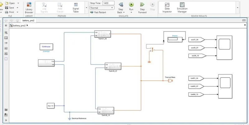
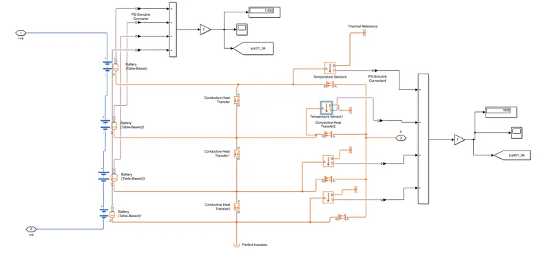
subsystem1(1 to 4 cells):
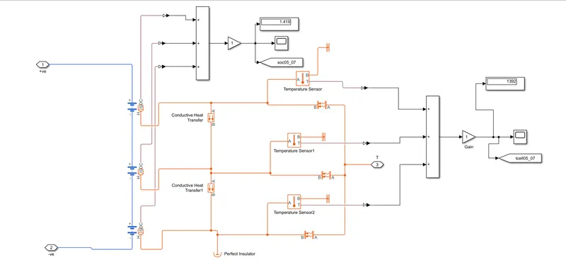
subsystem2(5 to 7 cells):
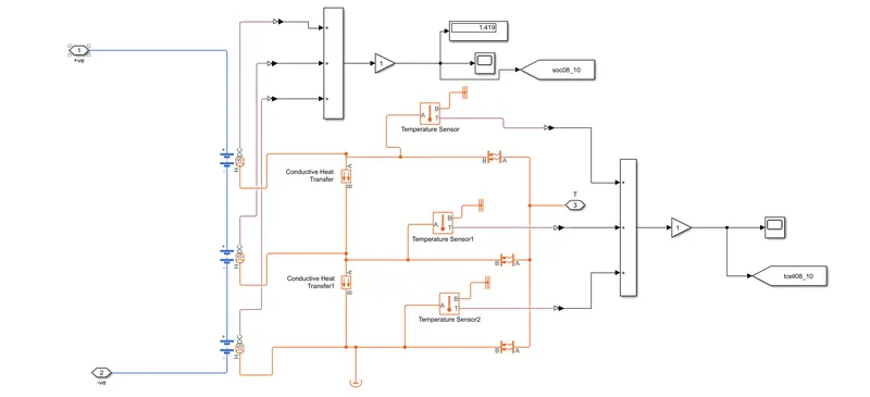
subsystem3(8 to 10 cells):
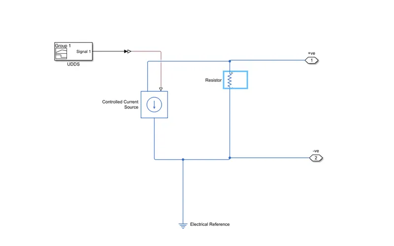
subsystem:(signals values)
blocks used to construct the model:
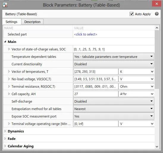
1.battery(table based):
The Battery (Table-Based) block represents a high-fidelity battery model. The block calculates no-load voltage as a function of charge level and optional temperature using lookup tables and includes several modeling options:
-
Self-discharge
-
Battery fade
-
Charge dynamics
-
Calendar aging
The Battery (Table-Based) block has two optional ports that you can expose by setting the corresponding parameters. The extra physical signal port, SOC, outputs the internal state of charge. Use this functionality to change the load behavior as a function of state of charge, without the complexity of building a charge state estimator. To expose the SOC port, in the Main setting, set the Expose SOC measurement port parameter to Yes.
To expose the thermal port, in the Thermal setting, set the Thermal port parameter to Model. The thermal port represents the battery thermal mass.
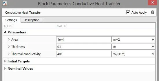
2.conductive heat transfer:
The Conductive Heat Transfer block represents a heat transfer by conduction between two layers of the same material. The transfer is governed by the Fourier law:
Q=k⋅AD(TA−TB)
where:
-
Q is heat flow.
-
k is thermal conductivity of the material.
-
A is area normal to the heat flow direction.
-
D is distance between layers (that is, thickness of material).
-
TA is temperature of layer A.
-
TB is temperature of layer B.
Connections A and B are thermal conserving ports associated with material layers. The block positive direction is from port A to port B. This means that the heat flow is positive if it flows from A to B.
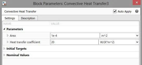
3.convective heat transfer:
The Convective Heat Transfer block represents a heat transfer by convection between two bodies by means of fluid motion. The transfer is governed by the Newton law of cooling:
Q=k⋅A⋅(TA−TB),
where:
-
Q is heat flow.
-
k is convection heat transfer coefficient.
-
A is surface area.
-
D is distance between layers (that is, thickness of material).
-
TA and TB are temperatures of the two bodies.
Connections A and B are thermal conserving ports associated with the points between which the heat transfer by convection takes place. The block positive direction is from port A to port B. This means that the heat flow is positive if it flows from A to B.
4.Temperature sensor:
The Temperature Sensor block represents an ideal temperature sensor, that is, a device that determines the temperature differential measured between two points without drawing any heat.
Connections A and B are thermal conserving ports that connect to the two points where temperature is being monitored. Port T is a physical signal port that outputs the temperature differential value.
The block positive direction is from port A to port B. The measured temperature is determined as T = TA – TB.
A port is associated with sensor positive probe
B port is associated with sensor negative probe
5.electrical reference:
The Electrical Reference block represents an electrical ground. Electrical conserving ports of all the blocks that are directly connected to ground must be connected to an Electrical Reference block. A model with electrical elements must contain at least one Electrical Reference block.
6.thermal reference:
The Thermal Reference block represents a thermal reference point, that is, a point with an absolute zero temperature, with respect to which all the temperatures in the system are determined.
7.solver configuration:
Each physical network represented by a connected Simscape block diagram requires solver settings information for simulation. The Solver Configuration block specifies the solver parameters that your model needs before you can begin simulation.Each topologically distinct Simscape block diagram requires exactly one Solver Configuration block to be connected to it.
8.signal builder:
The Signal Builder block allows you to create interchangeable groups of piecewise linear signal sources and use them in a model. You can quickly switch the signal groups into and out of a model to facilitate testing. In the Signal Builder window, create signals and define the output waveforms
scopes:
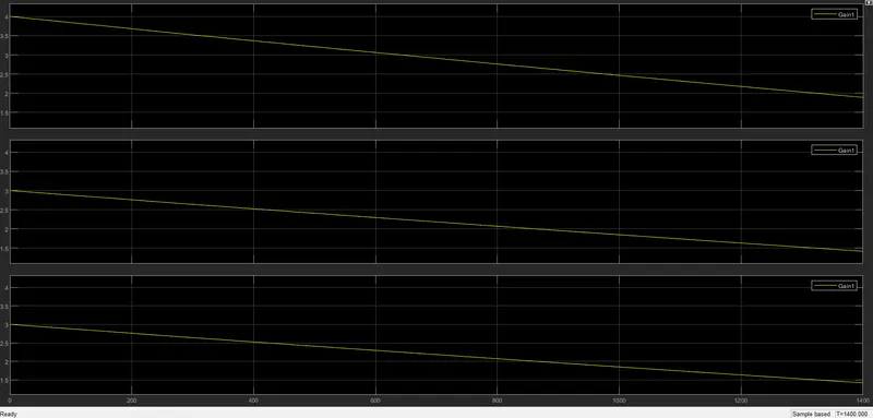
temperature scope:
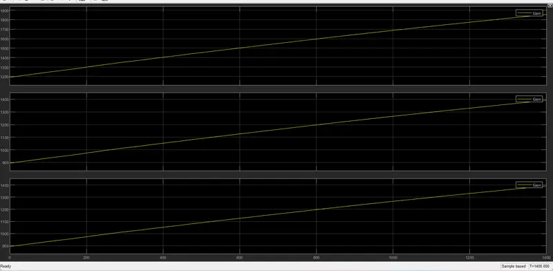
Results:
Ambient temperature provided by the temperature source is 293.15k
The cell pack 1-4 reaches the maximum temperature of 293.185k.cell pack 5-7 which is faulty cell reaches the maximum temperature of 293.214k,and cell pack 8-10 reaches the maximum temperature of 293.18k
The soc of the model starts from 0 to goes up to 0.9 in 1400 seconds