Project 2 Thermal modeling of battery pack
Aim: For a 10 cell series lithium-ion battery model, simulate the thermal effects and compare life cycle performance at various temperatures, charge & discharge rates using MATLAB.
Theory:
EV Thermal Management Systems: Its Importance in Electric Vehicle
The coming era of electric energy is changing the energy storage system of the vehicle from fossil fuels to electrochemical energy storage systems. This in turn is changing the propulsion system from the engine to the motor.
The change in energy storage and propulsion system is driving a revolution in the automotive industry to develop new energy vehicles with more electrified powertrain systems.
Lithium-ion (Li-ion) batteries have emerged as the most promising energy storage technology in recent years due to their higher energy density, lighter weight, no memory effect, and lower self-discharge rate when compared to other rechargeable batteries types.
These characteristics have brought them in limelight for use in electric vehicles (EV), hybrid electric vehicles (HEV), and plug-in hybrid electric vehicles (PHEV).
The continual commercialization of EVs in the global market by brands such as Tesla Model S, Nissan Leaf EV, BMW i3, Hyundai Kona Electric as well as Indian market with many big names entering the EV domain such as TATA with NEXON EV, the old school Mahindra REVA along with 2-wheeler domain with ATHER, OLA Electric, SIMPLE, Hero, etc., has further promoted the rapid development of Li-ion battery technology and raised a wide public expectation of its future.
Importance of Thermal Management for EVs?
Currently, most research into Li-ion batteries focuses on the material aspect to improve the specific energy, power, and cycle life, with relatively less attention paid to thermal-related issues.
Even the brands are using the terminologies such as range, and rapid charging which usually grabs the attention of customers. The end consumer is slowly getting convinced with the range capability for 2 wheeler, but still there exists range anxiety when looking at BEV in 4 wheeler domain.
To extend the total range of an electric car or SUVs, the volumetric energy density, with a unit of Wh·L−1, should be increased. Similarly, the gravimetric energy density also requires improvement for the range extension of the electric buses.
However, the materials with higher energy density may have lower thermal stability, leading to safety problems, e.g., thermal runaway (TR). The TR and TR-induced smoke, fire, and even explosion are the most common features during the accidents of lithium-ion batteries. Smoke, fire, and explosion are serious safety problems that arouse concerns from the public.
The fear of accident hinders the full acceptance of EVs from the market, therefore many countries require the lithium-ion battery to pass compulsory test standards, e.g., UN 38.3, UN R100, SAE-J2464, IEC-62133, GB/T 31485, etc., before its application in EV.
Impact of temperature on the life cycle of lithium-ion battery pack:
Lithium-ion batteries are popular power sources for cellphones and other electronics but are problematic in extreme heat or cold.
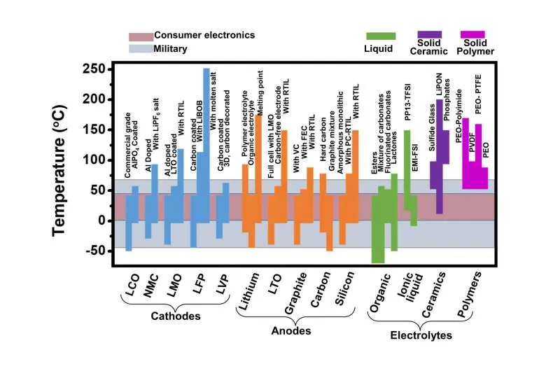
Li-ion cells have an optimal temperature operating range as shown in the figure below: outside this range, the battery cells undergo severe loss of capacity. High and low temperatures have different effects on battery life.
Most batteries will operate, with varying degrees of effectiveness in the 5- 35 °C range so are fine for the autumn and spring operating months, however, if you want a battery that will also operate efficiently in winter and summer you need to understand how temperature has an effect on batteries operating capabilities.
The ambient weather temperatures have a large impact on the performance and on the life of most batteries and unfortunately, it’s a characteristic that isn’t often talked about.
The optimum temperature for most batteries to operate at is around 25°C and this is the temperature all battery testing is performed at. When temperatures vary, either up or down there is an effect on the performance and life of most batteries.
Depending on the chemistry of the battery different batteries will only operate optimally within a limited temperature range, so it’s important to understand this when purchasing or upgrading your battery for energy storage.
When the temperature starts to fall below about 15°C, depending on the battery's chemistry, the electrochemistry of the battery becomes sluggish and doesn’t perform as well. In fact, very few batteries operate below 0°C. This is relevant in many countries in Europe, the USA or Canada but not as relevant in most of Australia.
What is relevant to the Australian market is the other end of the scale with the hot weather temperatures, particularly those of 40°C or above. Over 35°C, again depending on the battery chemistry, the battery will not operate and will start to degrade. For this reason, many batteries need to be kept in an air-conditioned environment which adds to the ongoing running costs of the battery and is something that needs to be taken into account when considering the LOC or lifetime cost of a battery. In the past, many installations have installed extra batteries, just to keep the air-conditioning running to keep the batteries cool.
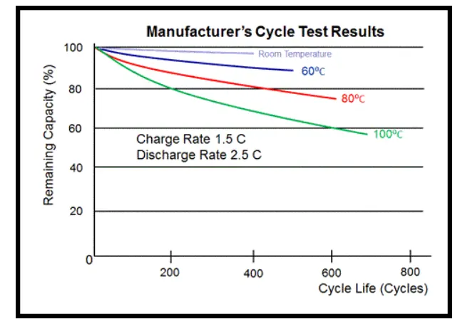
Keeping a battery within its safe operating range is critical in the case of certain battery technologies as some batteries will catch fire if they get too hot. This is one reason that certain batteries have a BMS or battery operating system included to make sure that the battery can’t overheat. However, if this BMS fails or there is no power for an extended period of time there is the possibility of batteries catching fire or exploding. (Just another thing to take into consideration.)
The FIAMM Sodium Nickel Chloride or SoNick batteries are the only batteries that will really work reliably in temperatures over 40°C and these temperatures don’t cause the SoNick battery to deteriorate so won’t have a detrimental effect on the batteries longevity. This is particularly important in hot areas of Australia or in bushfire prone areas.
Lithium-Ion (Li-ion) is an advanced technology that offers increased performance over nickel and lead-based chemistries at a price premium for custom battery packs and battery assemblies. Li-ion and Lithium Polymer can have twice the energy density of NiCd, can be capable of high discharge currents, and has relatively low self-discharge.
There are several major types of Lithium-Ion. Lithium Cobalt Oxide offers the best energy density. Lithium manganese offers greater safety with lower energy density than lithium cobalt oxide. Lithium Iron Phosphate offers a high discharge rate capability as well as a long cycle and calendar life. Some manufacturers offer mixed cathodes to optimize specific performance characteristics in lithium rechargeable cells.
Due to Lithium Ion’s high energy density and the inherent volatility of lithium as an element, each battery pack, and also single cells, require a special control circuit to manage their upper and lower voltage thresholds and to keep operating current and temperature within acceptable limits during charge and discharge.
Lithium-Ion battery technology is under constant improvement. New electrode materials promise improved capacity and better manufacturing techniques will continue to bring the price of Lithium Ion cells down, perhaps considerably.
The Lithium-Ion charge circuit is generally a two-stage constant current/constant voltage design. A fully discharged cell will take a constant current charge at a 1C rate (one time rated capacity) until it reaches a set voltage of between 3.6 volts and 4.2 volts, depending on the specific chemistry, which takes about one hour. Then, the charger switches to constant voltage, and the current tapers off until the battery is fully charged which takes about another two hours. The whole process takes about three hours, a fairly fast charge. Also, Lithium-Ion batteries may be removed from charge before fully charged with no side effects. Lithium-Ion will not tolerate overcharge conditions and therefore cannot be trickle charged.
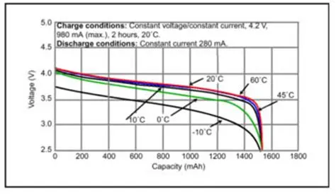
Discharge Vs. Temperature Characteristics of Li-ion battery
Impact of charge and discharge rates on the life cycle of Lithium-ion battery pack:
High currents generate more heat and cause the temperature of the cell to rise involving the high-temperature degradation mechanisms. Hight currents also cause local overpotential of the electrodes: it means that the maximum voltage for the cell is reached at an earlier stage in certain areas of the cell. High C-rates will also cause the SEI layer on the anode to crack faster. The more active anode material is exposed and the SEI layer will restore itself, reducing lithium ions from the battery cell process. High C-rates will furthermore cause additional strain on the electrode materials, resulting in increased deformation and loss of active materials. These effects will all result in capacity and power fading.
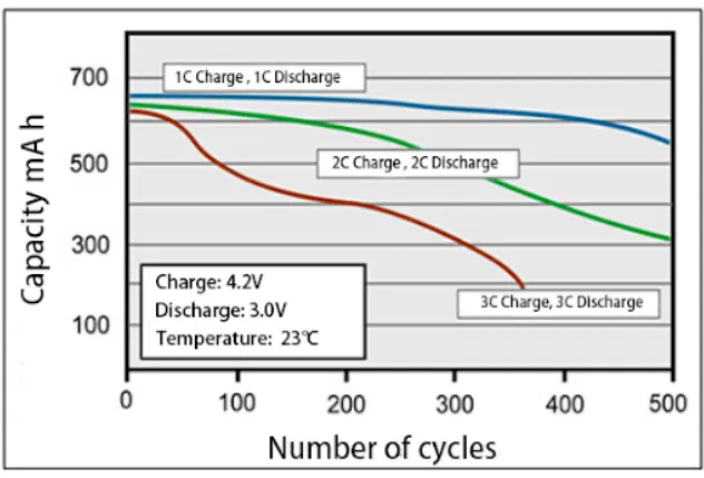
High C-rates cause increasing internal resistance (IR), loss of available energy, safety issues, and irreversible capacity loss. First, high C-rates cause lithium plating. When the Li-ion battery is charged with a high current, this forces the lithium ions to move at a faster rate while on the surface of the anode and form metallic lithium. This process is accelerated when the battery is fast charging at low temperatures and high SOC. Also, the lithium layer might elevate battery self-discharge. In extreme cases, it can cause battery inner short-circuiting and potentially lead to fires. Moreover, high charge and discharge current also cause more energy loss as part of the energy is transferred as heat because of battery IR. When the C-rates exceed a causes stress, damages the battery, and accelerates capacity loss. The figure below shows the discharge capacity degradation process of Li-ion batteries cycled under 1C, 2C and 3C which shows a severe acceleration of Li-ion battery capacity degradation with the increase of the C-rate. The higher the C-rate, the faster Li-ion batteries degrade. A C-rate of 0.8C or below is recommended for the energy cells to prolong battery life and ensure safety.
Abuse Conditions in Accidents and Internal Short-Circuits in Electric Vehicles
There can be two possibilities when considering accidents due to Thermal Runway (TR); one is a self-induced failure and the other is an abuse condition in practical use.
In the view of probability, the self-induced failure of the lithium-ion battery exists but at a very low level. The abuse conditions can be categorized as shown.
The Internal Short Circuit (ISC) is the most common feature of the Thermal Runway (TR). Almost all the abuse conditions are accompanied by ISC.
| Collision and crush | External Short Circuit | Local Overheat ( contact loose of cell connector) |
| Penetration | Over Charge | Overheat By Mechanical and electrical abuse |
| Over-Discharge |
Following the failure mechanism of the separator, the ISC can be divided into three categories considering the above-mentioned abuse conditions.
The hazard level of the ISC can be evaluated by the self-discharge rate and the exotic heat generation. It can be said that there are three levels of ISC as shown in the table.
To enhance the thermal performance of Li-ion batteries, reducing the amount of heat generated from the battery and boosting the heat dissipation rate are two feasible options:
- From the inside, it is the electrode in a battery cell that generates most of the heat during the charging/discharging processes, thus, an optimal design of electrode is crucial for minimizing the heat generation in the battery. This includes consideration of factors like the shape of the cell (whether prismatic, cylindrical, or pouch), thermophysical properties of electrodes, thermal and current distribution at the cell level, and an electrochemical reaction that takes place.
- From the outside, a thermal management system (TMS) implemented in battery packs can help to relieve the rapid temperature rise and improve the stability and safety of Li-ion batteries during charge and discharge procedures. This TMS can be implemented at the module level.
Electric Vehicle Thermal Management Systems
TMS is generally used for batteries operating under a high discharge rate, and especially for a large-scale battery pack that requires a long life cycle (>10 years) and is pricy to replace.
For example, all HEVs, PHEVs, and EVs are necessary to be equipped with Thermal Management Systems (TMS) due to the expensive battery repair, high cost of vehicles per SE, and relatively low automotive replacement rate.
In recent years, several techniques for readily removing heat from a battery pack have been tried and tested by various research groups across the globe. They can be classified in various ways, as seen.
The factors that are traditionally considered in the TMS trade-off analysis include energy efficiency, capital costs, ease of operation, maintenance requirements, and reliability. Cold plate and thermoelectric devices are not recommended for use in commercial systems, owing to their high thermal resistance and low coefficient of performance, respectively.
However, Gentherm Incorporation employs thermoelectric devices in their commercial design, whereas cold plates are used in the GMC Volt and Tesla Model S battery packs, signifying that both technologies have improved significantly in recent times.
Temperature range and temperature variation are two critical parameters influencing the battery pack performance. The ambient temperature may vary from -35 to +50 deg. Celsius in different regions, climates, and seasons, whereas the desired temperature range of the battery is about +15 ~ +35 deg. Celsius.
In addition, battery inconsistency and thermal boundary conditions result in temperature differences between cells in the battery pack. These major issues necessitate carefully designed Battery Thermal Management Systems (BTMS).
Conventional Thermal Management systems like fans and cold plates either have low scalability or deliver marginal performance (estimated from combined sets of cooling levels and regeneration rates) under challenging conditions. Other interesting alternatives (such as Thermoacoustic, Magnetic, etc. are available but they have not yet attained full technological maturity.
It is, therefore, concluded that a robust modular Thermal Management system (TMS) would be a hybrid system, designed through the union of at least two different TMSs. Considering factors such as technical risks, ease of integration, cost, and energy efficiency, it can be inferred that PCMs would form an integral part of the modular TMS assembly.
Battery Thermal Runaway in Electric Vehicle
Thermal runaway begins when the heat generated within a battery exceeds the amount of heat that is dissipated to its surroundings.
What causes the battery to overheat which leads to thermal runaway?
- Ambient Temperature
- Age of the Battery
- Float Charging Voltage
- Overcharging
Approaches to Minimize Thermal Runaway
The reduction of the Thermal Runway hazard can be fulfilled on three levels-
- First: improve the intrinsic safety of anti-TR properties by material modification;
- Second: set passive defence against the practical abuse conditions and develop an early warning algorithm before TR;
- Third: postpone or inhibit the secondary hazard, such as Thermal Runway propagation, to win sufficient time for the passenger to escape from the EV after the accident.
Simulink Model:
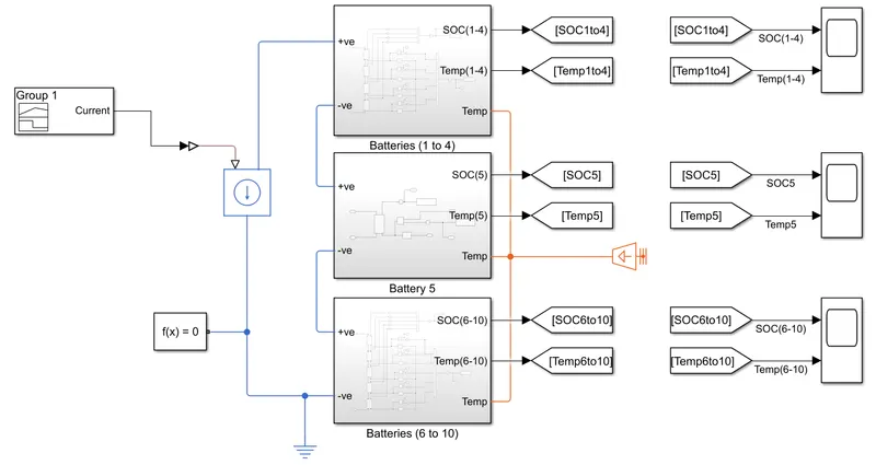
We have used a Battery Table-based block to create a battery pack of 10S1P configuration. They are divided into 3 Sub-systems and made of 1-4, 5th and 6-10 batteries packs as shown in the above figure.
The Input current is taken from Signal Block to the system and the output of SOC and Temperature is taken.
Blocks Used:
The Battery (Table-Based) block is used with instrumented and showing thermal port.
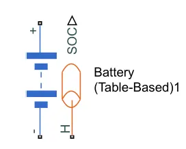
Parameters of the battery are kept default:
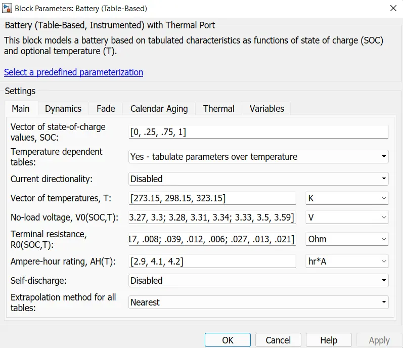
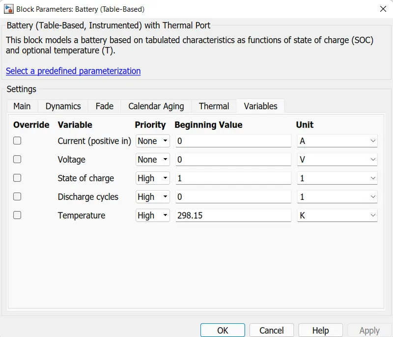
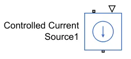
The Controlled Current Source block which -ve and +ve terminal are connected to the +ve and -ve terminal of the battery respectively. PS constant is connected to this block with a 2.1A current flow.
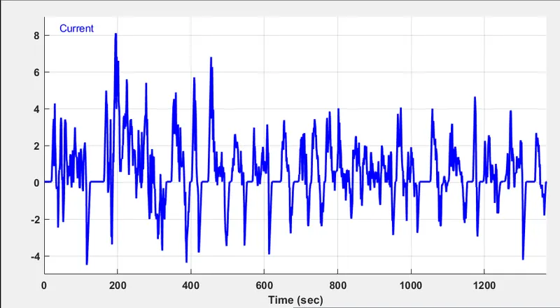
The Controlled current sensor block receives current from the Signal Builder block where the values of the UDDS cycle's speed to time are taken as current to time values.

The UDDS drive cycle is used in the battery pack.
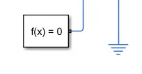
Electrical reference and solver configuration are connected to the battery circuit.
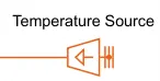
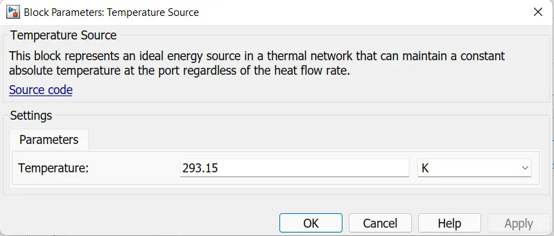
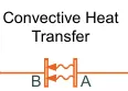
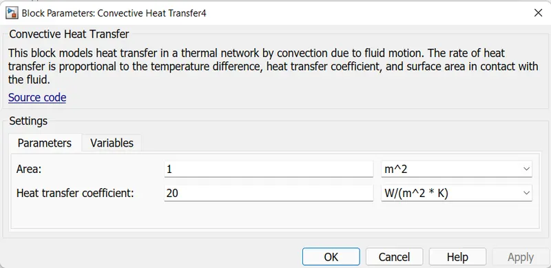
The Temperature Source block is connected to the Battery to thermal connection via Convective Heat Transfer. The area is kept at 0.0001 m^2.
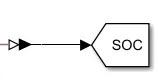
The SOC terminal is connected to the goto block via the PS-Simulink converter block.
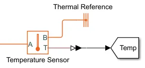
The Temperature Sensor block is connected to the thermal battery circuit A, B and T terminal is connected to the circuit, Thermal Reference and the goto block for temperature values via PS-Simulink converter block respectively.
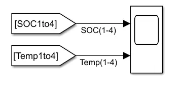
The From block of the SOC and Temp are connected to the scope to get graphs of both values.
Case 1: If each and every battery in the pack is working properly i.e., in all subsystems.
1st Sub-system of 1-4 Battery Pack:
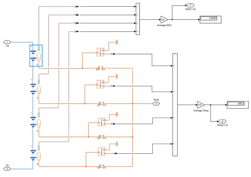
Here 4 battery table-based is used with block choice of instrumented and showing thermal point. They are connected in series +ve is connected to the -ve terminal. The +ve and -ve terminals are taken inputs from the outside subsystem.
All SOC output from the battery is taken to ADD Block and is connected to Gain Block to get the average and connected to the Output terminal of SOC and Display Block to show the reading.
All Temperature output from the battery is taken to ADD Block and is connected to Gain Block to get the average and connected to the Output terminal of Temperature and Display Block to show the reading.
Both the connections are shown in the above figure.
2nd Sub-system of 5th Battery pack:
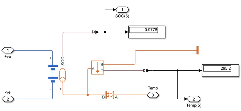
The connection is similar to the above figure but uses a single battery.
3rd Sub-system of 6-10 Battery Pack:
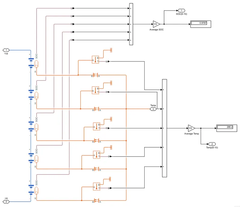
The connection is similar to the above figure but uses a 5 battery.
Results:
The values are shown in the display block.
| Battery Pack | Batteries | SOC (in %) | Temperature (in °C) |
| 1 | 1-4 | 97.78 | 295.2 |
| 2 | 5 | 97.78 | 295.2 |
| 3 | 6-10 | 97.78 | 295.2 |
Graphs:
1-4 Battery Pack:
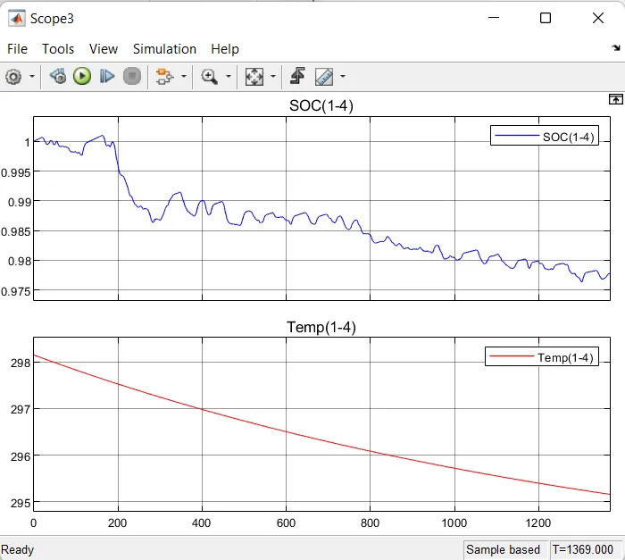
Here we can observe that SOC is reduced to 0.9778 from 1 and Temperature is reduced to 295.2 °C from 298.15 °C.
5th Battery Pack:
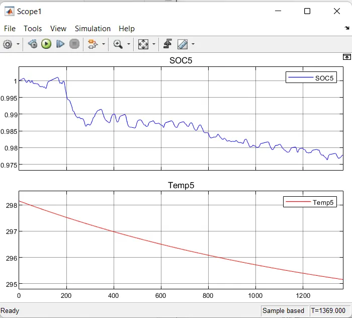
Here we can observe that SOC is reduced to 0.9778 from 1 and Temperature is reduced to 295.2 °C from 298.15 °C.
6-10 Battery Pack:
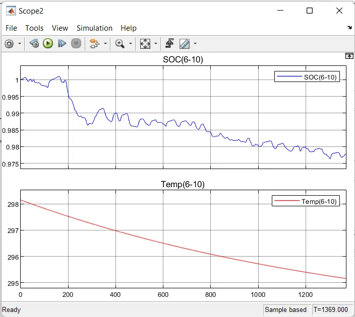
Here we can observe that SOC is reduced to 0.9778 from 1 and Temperature is reduced to 295.2 °C from 298.15 °C.
From the three graphs, we can observe that the SOC and Temperature values don't change in all three sub-systems as they are connected in series.
Case 2: If the 5th battery in the pack is connected to a resistor of 5 ohms i.e., 2nd subsystem. And other batteries are working in good condition.
2nd Sub-system of 5th Battery pack:
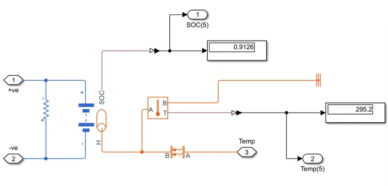 Here, a 5-ohm battery is connected to the battery in the circuit to see the imbalances in SOC and Temperature values.
1st and 3rd Sub-systems are the same as above shown.
Results:
The values are shown in the display block when the resistor of 5 ohms is connected in the model.
| Battery Pack | Batteries | SOC (in %) | Temperature (in °C) |
| 1 | 1-4 | 97.78 | 295.2 |
| 2 | 5 | 91.26 | 295.2 |
| 3 | 6-10 | 97.78 | 295.2 |
1-4 Battery Pack:Graphs:
Here we can observe that SOC is reduced to 0.9778 from 1 and Temperature is reduced to 295.2 °C from 298.15 °C.
5th Battery Pack:
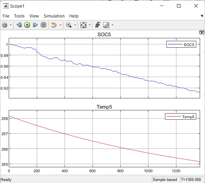
Here we can observe that SOC is reduced to 0.9126 from 1 and Temperature is reduced to 295.2 °C from 298.15 °C.
6-10 Battery Pack:
Here we can observe that SOC is reduced to 0.9778 from 1 and Temperature is reduced to 295.2 °C from 298.15 °C.
From the three graphs, we can observe that the SOC and Temperature values don't change in all three sub-systems as they are connected in series.
Comparing Case 1 and Case 2:
When the resistor of 5 ohms is connected in series with the 5th battery we can observe that the SOC value is reduced to 91.26% from 100% and the Temperature is reduced to 295.2 °C from 298.15 °C which is the same as without the resistor as its value is too less to get the difference in temperature.
When the resistor is connected it drains out the battery soon as compared without the resistor.
The table is also plotted in both cases according to the results.