Project 2 Thermal modeling of battery pack
Lithium-ion battery
A lithium-ion battery is a family of rechargeable battery types in which lithium ions move from the negative electrode to the positive electrode during discharge and back when charging. Chemistry, performance, cost and safety characteristics vary across lithium-ion battery types. Unlike lithium primary batteries (which are disposable), lithium-ion batteries use an intercalated lithium compound as the electrode material instead of metallic lithium.
A lithium-ion (Li-ion) battery is an advanced battery technology that uses lithium ions as a key component of its electrochemistry. During a discharge cycle, lithium atoms in the anode are ionized and separated from their electrons. The lithium ions move from the anode and pass through the electrolyte until they reach the cathode, where they recombine with their electrons and electrically neutralize. The lithium ions are small enough to be able to move through a micro-permeable separator between the anode and cathode. In part because of lithium’s small size (third only to hydrogen and helium), Li-ion batteries are capable of having a very high voltage and charge storage per unit mass and unit volume.
Li-ion batteries can use a number of different materials as electrodes. The most common combination is that of lithium cobalt oxide (cathode) and graphite (anode), which is most commonly found in portable electronic devices such as cellphones and laptops. Other cathode materials include lithium manganese oxide (used in hybrid electric and electric automobiles) and lithium iron phosphate. Li-ion batteries typically use ether (a class of organic compounds) as an electrolyte.
10 cell series lithium ion battery model:
Componends
1.Lithium cell
This cell has a set of subsystem which helps to analyse the properties of lithium ion cell
The properties for the cell
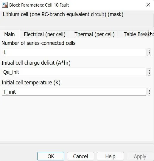
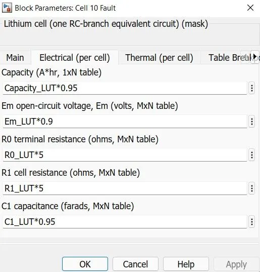
Subsystem in the lithum cell
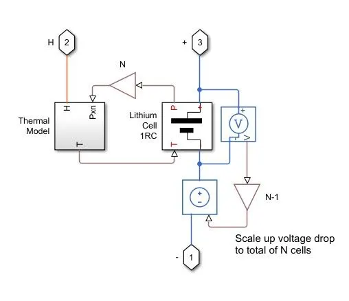
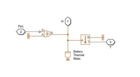
The above subsystems were consists of lithium cell, voltage source, voltage sensor and etc. And also it has a thermal model subsystem which has a battery thermal mass,temperatre sensor and etc. Temperature sensor measures temperature in a thermal network. There is no heat flow through the sensor. The physical signal port T reports the temperature difference across the sensor. The measurement is positive when the temperature at port A is greater than the temperature at port B. controlled heat flow rate sourse represents an ideal energy source in a thermal network that can maintain a controlled heat flow rate regardless of the temperature difference. The heat flow rate is set by the physical signal port S. A positive heat flow rate flows from port A to port B.
2.AC current source
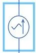
It provides the current to the battery unit. The ideal AC current source maintains the sinusoidal current through it, independent of the voltage across its terminals.
3.Conductive heat transfer:

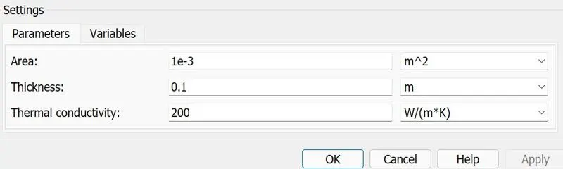
This block models heat transfer in a thermal network by conduction through a layer of material. The rate of heat transfer is governed by Fourier's law and is proportional to the temperature difference, material thermal conductivity, area normal to the heat flow direction, and inversely proportional to the layer thickness.The parameters for this block is given below
4. Convective heat source:

This block models heat transfer in a thermal network by convection due to fluid motion. The rate of heat transfer is proportional to the temperature difference, heat transfer coefficient, and surface area in contact with the fluid.
5.Temperature source:

This block represents an ideal energy source in a thermal network that can maintain a constant absolute temperature at the port regardless of the heat flow rate.
6.Electrical refferenc:
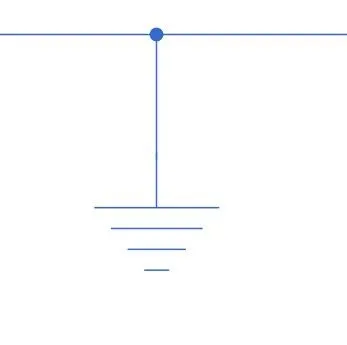
Electrical reference port. A model must contain at least one electrical reference port (electrical ground).
7.Thermal refference:
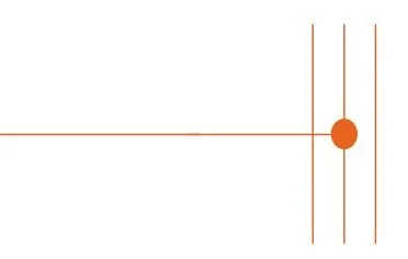
This block represents a reference point in a thermal network where the temperature is equal to absolute zero.
8.Temerature sensor:
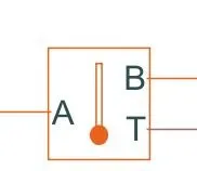
This block measures temperature in a thermal network. There is no heat flow through the sensor. The physical signal port T reports the temperature difference across the sensor. The measurement is positive when the temperature at port A is greater than the temperature at port B.
9.Current sensor
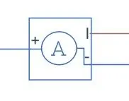
The block represents an ideal current sensor, that is, a device that converts current measured in any electrical branch into a physical signal proportional to the current.
Connections + and - are conserving electrical ports through which the sensor is inserted into the circuit. Connection I is a physical signal port that outputs current value.
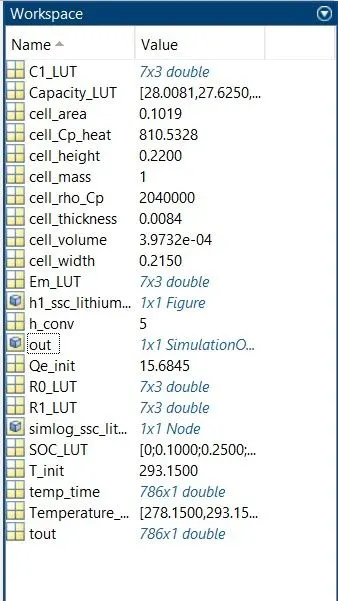
Workspace parameters:
Simulink model :
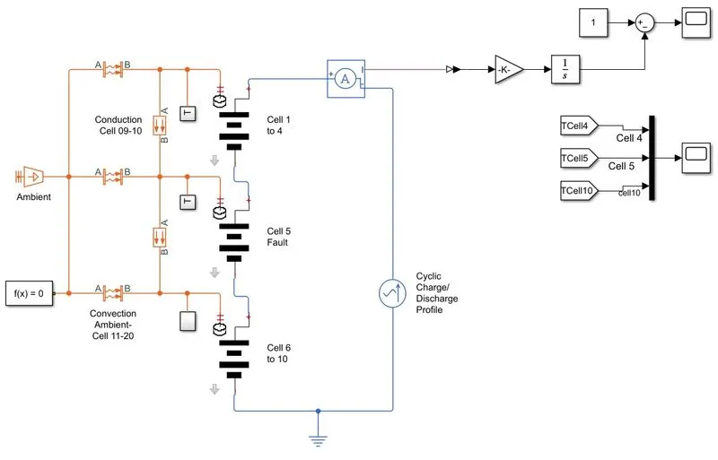
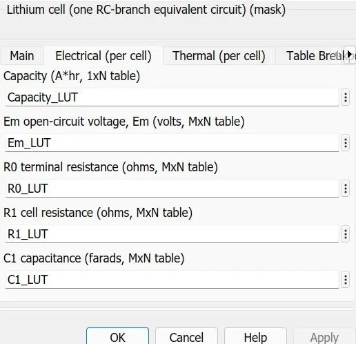
The above model is the complete circuit to analyze the thermal properties of a battery.Here the three modeles were used. There are total 10 numbers of cell present in the module. First module has a four cells. And second module has 1 cell that has a fault in it. To create fault in the system the properties of the battery have to change . The changed properties and unchanged properties were given below
- The current source developed by the AC current source block that powers up the system and this current value has been pass through current sensor which helps to measure the current value.
- The current value then integrated through gain block to find the SOC of the system.
- Then the signals were goes to three cells block where the where the system evaluate the battery behaviour.
- Battery block has a thermal output port which feed the signal to the thermal convective block.
- Before that there is a subsystem which helps to measure the thermal value of the system.
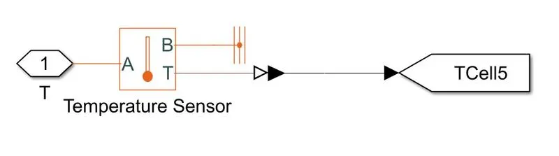
- The above subsystem includes sensor block which measure the temperature value of the battries.
- Then the signals were plotted by using scope block.
- Inbetween the two convective heat transfer block there is a conductive block were placed which helps heat transfer in a thermal network by conduction through a layer of material. The rate of heat transfer is governed by Fourier's law and is proportional to the temperature difference, material thermal conductivity, area normal to the heat flow direction, and inversely proportional to the layer thickness.
- The thermal and electrical reference blocks were connected to the corresponding requirments.
Results:
The total simulation ran for 5000seconds
SOC for Battery pack:
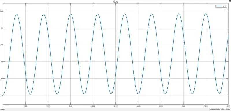
We can see that the soc of the battery pack goes between 0 and below 100. The values goes up and down for frequent time intervales. Because we feed the AC current source so based on the ac current value the soc can be defined.
Temperature difference for three cells:
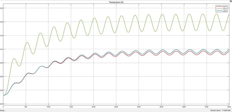
The above plot shows clear difference between these three cells. The cell 1-4 and 6-10 were reacted almost same but in case of cell 5 we can see the more deviation becase we porposly made some modification to the cell to make it faulty. So by made this change we can see the behaviour of a faulty cell it helps to analyze the cell if it will failier in future.
Condution properties of cell 5 :
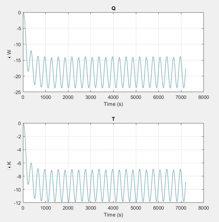
The values were goes to the negative zone for a faulty cell from 0.
The minimum value of Thermal conductivity = -11.64 K
The minimum value of heat teansfer = -23.34 W/m2K.
Condution properties of cell 6:
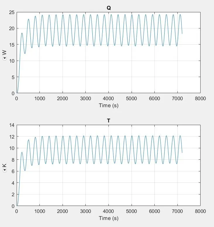
The values were goes to the positive zone for a normal cell from 0.
The maximum value of Thermal conductivity = 12.08 K
The maximum value of heat teansfer = 24.18 W/m2K.
Convective properties of cell 1-4:
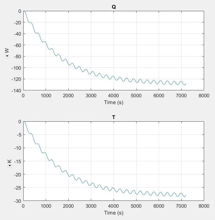
The minimum value of Thermal conductivity = -28.39 K
The minimum value of heat teansfer = -130.60 W/m2K.
Convective properties of cell 5:
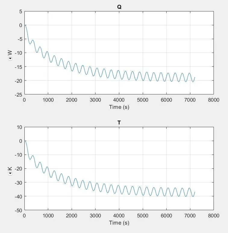
The minimum value of Thermal conductivity = -39.98 K
The minimum value of heat teansfer = -20.52 W/m2K.
Convective properties of cell 6-10:
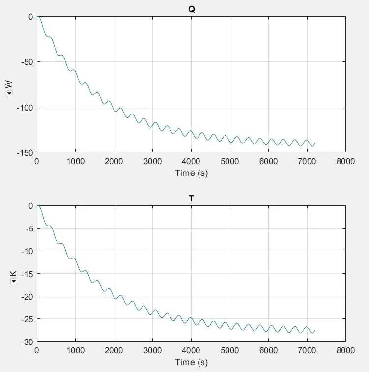
The minimum value of Thermal conductivity = -28.02 K
The minimum value of heat teansfer = -143.25 W/m2K.
Charge and discharge plot for the battery pack:
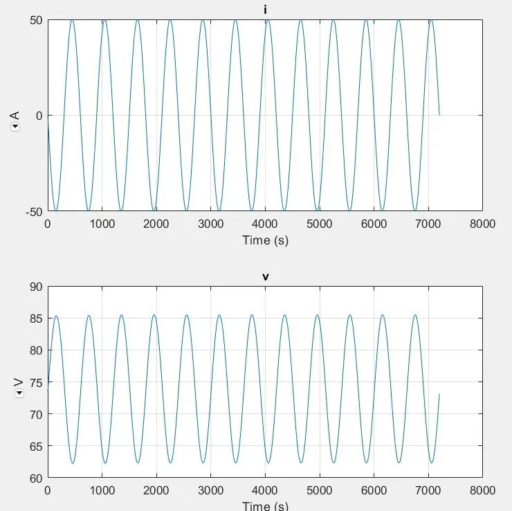
The above plot shows the value for voltage and curent which reperesent charging and discharging cycles. The voltage beggines with 75V and fluxuates with respect to the input and goes upto 85.5V also goes minimum of 63V. In the case of current it statrs from 0 and goes upto 50A and goes minimum of -50 becaude the input source is AC current.
Reference: