Project 2 - Speed Control of a Direct Current (DC) motor
Aim: To design a model to control the speed of a direct current DC motor.
Software used : Matlab (Simulink )
Specification : Controlling dc motor using PID controller kp- proportional gain, kd- derivative gain, ki-integral gain.
Theory :
- Mathematical modeling from the first principles
Legend:
uS – field winding voltage
uR – armature winding voltage
iS – field winding current
iR – armature winding current
RS – field winding resistance
RR – armature winding resistance
LS – field coil inductance
LR – armature coil inductance
MSR – mutual inductance
ωm – angular speed of the engine rotation
mC, mm – moment of conversion and load
Jm – total engine inertia torque
Bm – coefficient of viscous friction
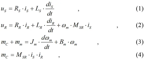
- Modeling an Electrical Engineering system
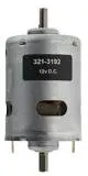
- Here the Speed control of a DC motor is either done manually by the operator or by means of an automatic control device.
- This is different to speed regulation where the speed is trying to be maintained or regulated against the natural change in speed due to a change in the load on the shaft
-
so the speed can be varied by changing:
- The terminal voltage of the armature V
- The external resistance in armature circuit Ra
- The flux per pole
-
So Terminal voltage and external resistance involve a change that affects the armature circuit while flux involves a change in the maginetic field
-
so Therefore speed control of DC motor can be classified into:
- Armature Control Methods
- Field Control Methods
Simulink model :
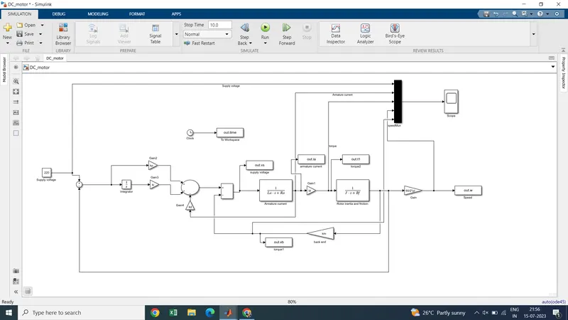
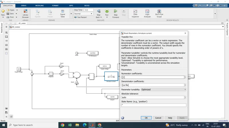
- Here first we need to creat simulink model of the DC motor and make it as subsytem called the DC motor
- So next the subsytem of DC motor is connected to the discrete PID controller which helps in maintaining the desired speed
-
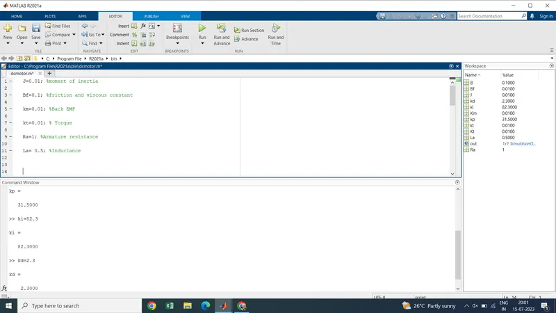
J=0.01; %moment of inertia
Bf=0.1; %friction and viscous constant
km=0.01; %Back EMF
kt=0.01; % Torque
Ra=1; %Armature resistance
La= 0.5; %Inductance
Here we consider the PID control paramters as :
Kp =1 ;
ki = 1;
kd =0;
Blocks used for modelling
- Transfer function
- constant
- gain
- mux
- scope
- clock
- To workspace
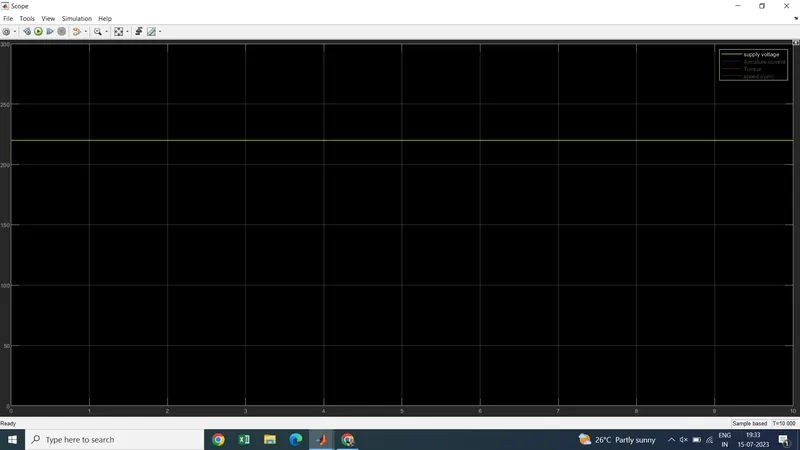
Results : With continuous steps.
1. Supply Voltage
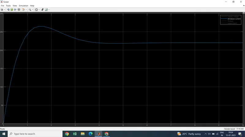
2. Armature current
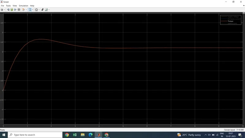
3. Torque - At start there is high start torque then it stablise the torque at 3.5 sec
4. Speed
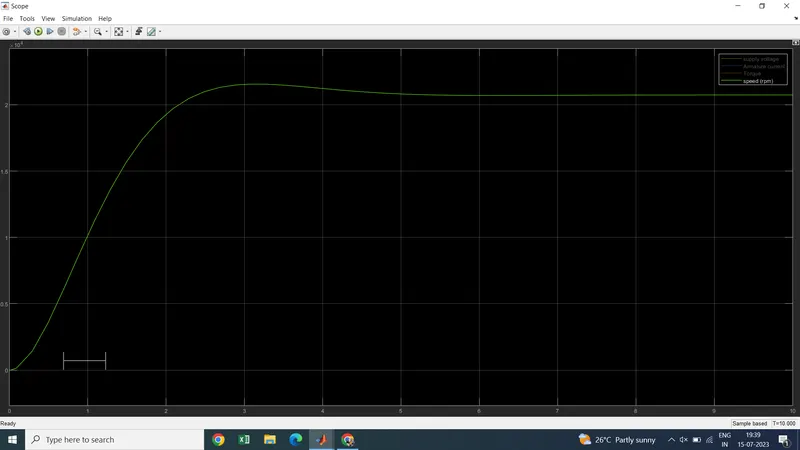
now changing with the values of PID control as
kp=31.5;
ki=82.3;
kd=2.3;
Results :
1.supply voltage
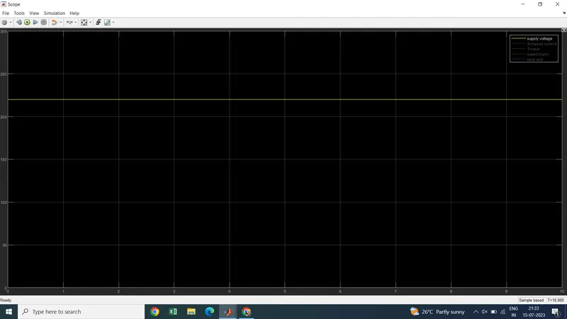
2.Armature current
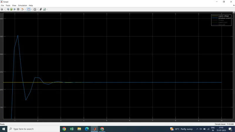
3. Torque
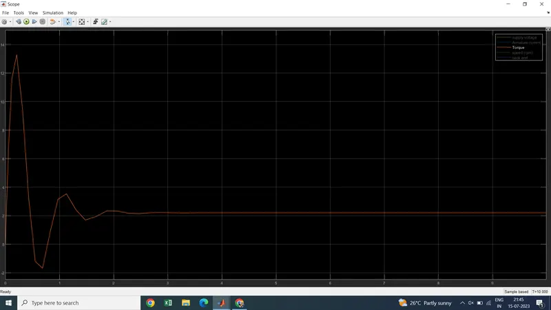
Back EMF : Some amount of back emf generated with the motoring option
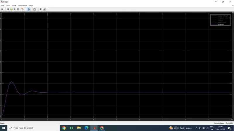
4. Speed: This waveform says that we can operate our desire speed control with the use of PID controller and it proves this model.
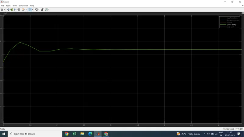
- Here by observing the above two graphs we change the desired speed .
- As the armature control changes the speed of the motor can be controlled .
Conclusion:
We have design Simulink model for the DC motor and also we Use the Proportional Integral and Derivative PID control design knowledge gained in the training to design develop and test a controller to maintain a desired speed for the motor and successfully estalished.