Project 2 - Review of Shear, Moment & Splice connections in StaadPro Connection Module
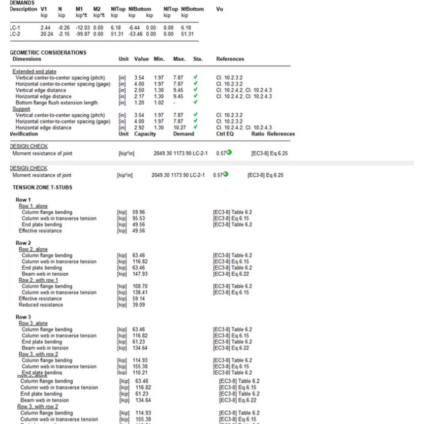
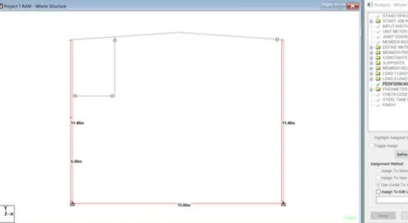
Design and optimize typical shear, moment and Splice joints in Staad Connection module for the following structure modelled in staadpro. Generate Report.
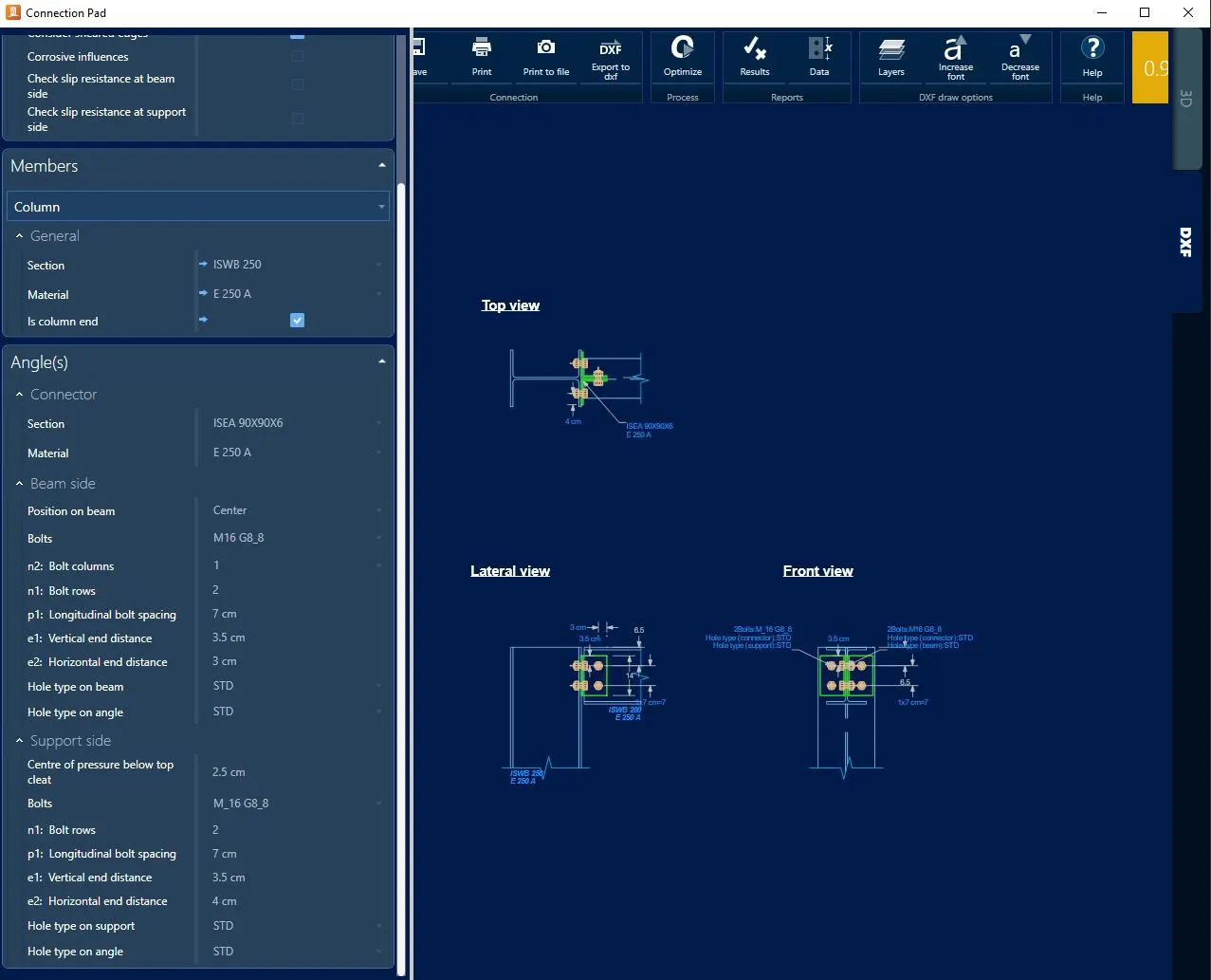
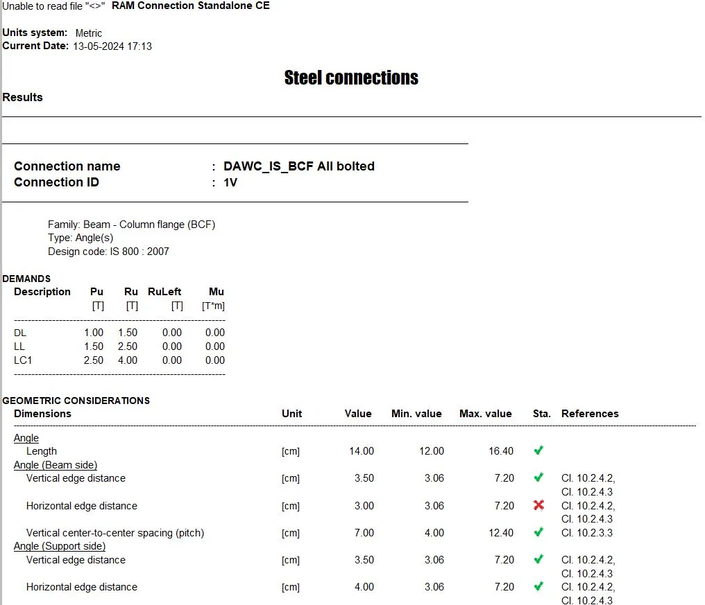
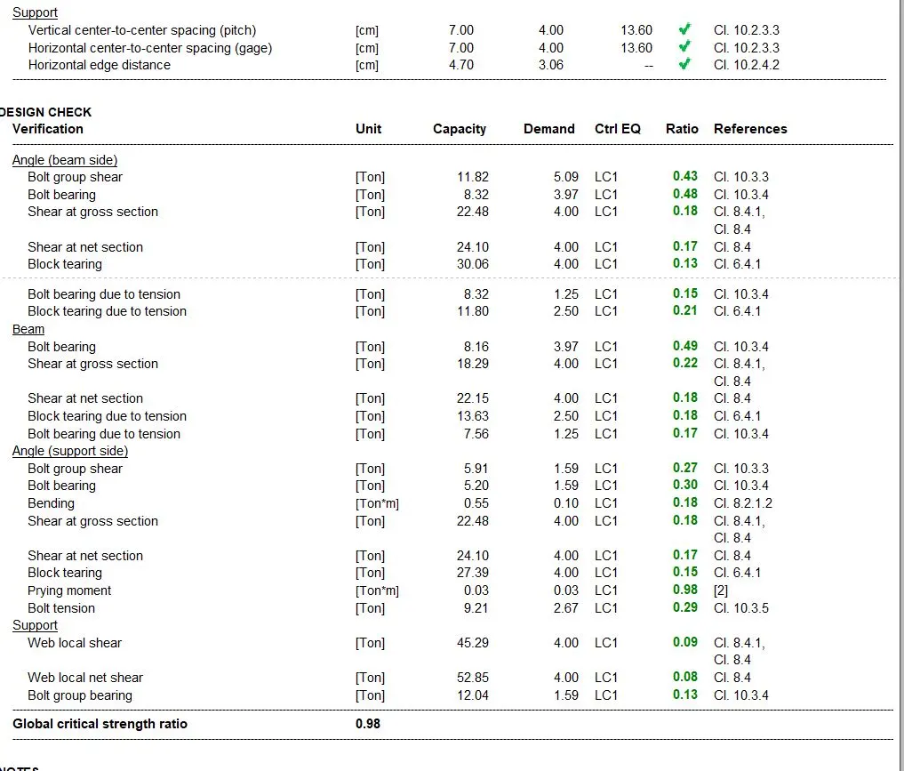
Design and optimize braced connection (use US standard connections) in RAM Connection.
Structure:
- A 2D portal frame fixed support spanning 15m with a
- pitched roof ridge height of 12m with
- eaves Height of 11.5m.
- A uniformly distributed load of 10kN/m is applied on the roof beams.
- Optimize the beams and columns for 85% utilization and
- consider splice joints at 6m
- from base and 3m from beam column joints.
- Consider a hanger beam shear connected with column support of 4m height at 3m from
- beam-column corner joint carrying 5kN/m vertical load and 5kN horizontal load,
- hanger beam end is tied with a brace to the eave.
- Design Foundations using STAAD Foundation.
- Attach necessary sketches and drawings wherever required.
- All stipulations, assumptions and design parameter must adhere to Indian Standards.
- To calculate the wind pressure and sesimic load cases first we need to calculate the centre height of the sturucture given that the slope roof is 1 in 10 then center height of the structure is calculated as
- x/20=1/10 then x=2
- then the centre height = clear height + slope height = 10+2 = 12
Step-2:
- open stadd pro and create new project in that select the units as metric then the stadd model will appear.
- Given the structural modal of an industrial building dimensions and considerations are
Width = 40m
Height = 10m
Length = 80m
Bay spacing = 6m
Location = Mumbai
Soil Type = Hard
- Then create a model by modal displacement method and enter the origin as (0,0) and also enter the nodes (40,0),(0,10),(40,0) nodes for the creating the modal.
- and next go to the geomentry window in that go to cerate beam or add beam option and add beam in the given nodes.
- create a node at the centre from the right support then consider the height of the node will be centre height of the structure and in the middle of the span of the two beams ie (20,12).
- add the beam from the node to the center point.
- create a another nodes at the center and add beam.
- To have a two evenly spaced nodes in between select the beam and go to the Insert node option In that give the value of n=2 for two nodes which are equally spaced.
- add beams to the given nodes and to have a perpendicular Intersections go to add beam options in that we have a option of perpendicular intersections and click on that option and add beams at the nodes.
- and copy the nodes and paste it at height of 12m and add beams by add beam option.
- To stop the beams at the intersecton of the frames, select the beams and go for the intersecting beams option in that click on intersect the selected beams option and give Tolerance as "0" and click ok.
- remove the unwanted beams and add the beams at the center.
- Now replicate the middle beams to the next side to replicate the beams go to mirror option select the beams at click on to the referene plane node to replicate at that point.
- then next step is repliacte the main frame alone.select the beam members and select the beams present in the main frame,
- nd copy the nodes and paste it at height of 12m and add beams by add beam option.
- To stop the beams at the intersecton of the frames, select the beams and go for the intersecting beams option in that click on intersect the selected beams option and give Tolerance as "0" and click ok.
- remove the unwanted beams and add the beams at the center.
- Now replicate the middle beams to the next side to replicate the beams go to mirror option select the beams at click on to the referene plane node to replicate at that point.
- then next step is repliacte the main frame alone.select the beam members and select the beams present in the main frame,
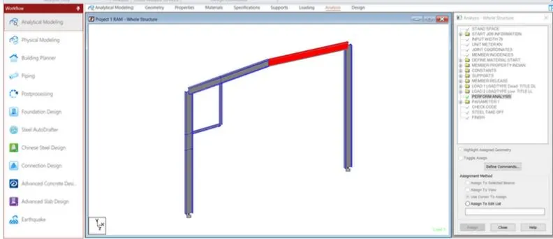
- go to the ram software interface
- and next go to the geomentry window in that go to cerate beam or add beam option and add beam in the given nodes.
- create a node at the centre from the right support then consider the height of the node will be centre height of the structure and in the middle of the span of the two beams ie (20,12).
- add the beam from the node to the center point.
- create a another nodes at the center and add beam.
- To have a two evenly spaced nodes in between select the beam and go to the Insert node option In that give the value of n=2 for two nodes which are equally spaced.