Creation of geometries by Coordinate system methods using AutoCad

1. Absolute cooardinate system:
- In the absolute coardinate system the following steps should be followed as a procedure. At first open the autocad and set dimensions that the dimensions are in mm.
- Then enter the Line command in autocad and after that enter the first point of the given diagram as (2,1) that line should be started at the point (2,1) in the coardinate system.
- From that point enter the dimensions of 6 units along X- axis that given in the dimensions and Y- axis as zero.
- after that from that point enter the dimensions 1 along the y- axis and X - axis as zero then the another line is generated.
- contionously take the dimensions of X-axis as -5 and y-axis as 0 to get the anpther point in the coardinate axis.
- from that point take the x- axis as 0 and y-axis as 4 to get the another point of the line in that coardinate system.
- from that point next in x- axis as 5 and y-axis as 0 to get the another end.
- from that point next in x- axis as 0 and y-axis as 1 to get the another end.
- from that point next in x- axis as -6 and y-axis as 0 to get the another end.
- from that we have a ption called close point or from that point take the x-axis s 0 and y-axis as -6 to get the end point.
2. Relative coordinate system:
- In the relative coordinate system the following steps should be followed as a procedure. At first open the autocad and set dimensions that the dimensions are in mm.
- Then enter the Line command in autocad and after that enter the first point of the given diagram as (2,1) that line should be started at the point (@2,1) in the coardinate system.
- From that point enter the dimensions of 6 units along X- axis that given in the dimensions and Y- axis as zero ie (@6,0).
- after that from that point enter the dimensions 1 along the y- axis and X - axis as zero then the another line is generated ie (@0,1).
- contionously take the dimensions of X-axis as -5 and y-axis as 0 to get the anpther point in the coardinate axis ie (@-5,0).
- from that point take the x- axis as 0 and y-axis as 4 to get the another point of the line in that coardinate system ie (@0,4).
- from that point next in x- axis as 5 and y-axis as 0 to get the another end ie (@5,0).
- from that point next in x- axis as 0 and y-axis as 1 to get the another end ie (@0,1).
- from that point next in x- axis as -6 and y-axis as 0 to get the another end ie (-6,0).
- from that we have a ption called close point or from that point take the x-axis s 0 and y-axis as -6 to get the end point ie (@0,-6).
3. polar coordinate system:
- In the polar coordinate system the following steps should be followed as a procedure. At first open the autocad and set dimensions that the dimensions are in mm.
- Then enter the Line command in autocad and after that enter the first point of the given diagram as (2,1) that line should be started at the point (2,1) in the coardinate system.
- From that point enter the dimensions of 6 units along X- axis that given in the dimensions and the angle as zero ie (6<0).
- after that from that point enter the dimensions 1 along the y- axis and angle as 90 degrees then the another line is generated ie (1<90).
- contionously take the dimensions of X-axis as 5 and angle as 180 degrees to get the another point in the coardinate axis ie (5<180).
- from that point take the angle at 90 degrees and y-axis as 4 to get the another point of the line in that coardinate system ie (4<90).
- from that point next in x- axis as 5 and angle as 90 to get the another end ie (5<90).
- from that point next in x- axis as 1 and angle as 90 to get the another end ie (1<180).
- from that point next in x- axis as -6 and angle 180 to get the another end ie (6<180).
- from that we have a ption called close point or from that point take the x-axis s 6 and angle as 90 to get the end point ie (6<90).
4. Direct coordinate system:
- In the polar coordinate system the following steps should be followed as a procedure. At first open the autocad and set dimensions that the dimensions are in mm.
- Then enter the Line command in autocad and after that enter the first point of the given diagram as (2,1) that line should be started at the point (2,1) in the coardinate system.
- from that point show the point of mouse curser to the direction of positive x axis and enter the value 6 in the direction.
- piont out the direction to positive y-axis and enter the value as 1.
- and again point the mouse curser to the negative x- axis and enter the value as 5.
- point the mouse curser to the positive y- axis and enter the value as 4
- point the mouse curser to the positive x- axis and enter the value as 5
- point the mouse curser to the positive y- axis and enter the value as 1
- point the mouse curser to the negative x- axis and enter the value as 6
- point the mouse curser to the negative y- axis and enter the value as 6

1. Absolute cooardinate system:
- In the absolute coardinate system the following steps should be followed as a procedure. At first open the autocad and set dimensions that the dimensions are in mm.
- Then enter the Line command in autocad and after that enter the first point of the given diagram as (2,1) that line should be started at the point (2,1) in the coardinate system.
- From that point enter the dimensions of 3 units along X- axis that given in the dimensions and Y- axis as zero.
- after that from that point enter the dimensions 3 along the y- axis and X - axis as zero then the another line is generated.
- contionously take the dimensions of X-axis as 1 and y-axis as 0 to get the anpther point in the coardinate axis.
- from that point take the x- axis as 0 and y-axis as -3 to get the another point of the line in that coardinate system.
- from that point next in x- axis as 5 and y-axis as 7 to get the another end.
- from that point next in x- axis as -2 and y-axis as 0 to get the another end.
- from that we have a ption called close point to get the end point.
2. Relative coordinate system:
- In the relative coordinate system the following steps should be followed as a procedure. At first open the autocad and set dimensions that the dimensions are in mm.
- Then enter the Line command in autocad and after that enter the first point of the given diagram as (2,1) that line should be started at the point (@2,1) in the coardinate system.
- From that point enter the dimensions of 3 units along X- axis that given in the dimensions and Y- axis as zero ie (@3,0).
- after that from that point enter the dimensions 4 along the y- axis and X - axis as zero then the another line is generated ie (@0,4).
- contionously take the dimensions of X-axis as 0 and y-axis as -4 to get the anpther point in the coardinate axis ie (@0,-4).
- from that point take the x- axis as 0 and x-axis as 3 to get the another point of the line in that coardinate system ie (@3,0).
- from that point next in x- axis as 5 and y-axis as 7 to get the another end ie (@5,7).
- from that point next in x- axis as 3 and y-axis as 0 to get the another end ie (@3,0).
- from that point next in x- axis as -6 and y-axis as 0 to get the another end ie (-6,0).
- from that we have a ption called close point to get the end point.
3. polar coordinate system:
- In the polar coordinate system the following steps should be followed as a procedure. At first open the autocad and set dimensions that the dimensions are in mm.
- Then enter the Line command in autocad and after that enter the first point of the given diagram as (2,1) that line should be started at the point (2,1) in the coardinate system.
- From that point enter the dimensions of 3 units along X- axis that given in the dimensions and the angle as zero ie (3<0).
- after that from that point enter the dimensions 4 along the y- axis and angle as 90 degrees then the another line is generated ie (4<90).
- contionously take the dimensions of X-axis as 1 and angle as 0 degrees to get the another point in the coardinate axis ie (1<0).
- from that point take the angle at 270 degrees and y-axis as 4 to get the another point of the line in that coardinate system ie (4<270).
- from that point next in x- axis as 3 and angle as 0 to get the another end ie (3<0).
- from that point next in x- axis as 7 and angle as 35 to get the another end ie (7<35).
- from that point next in x- axis as 3 and angle 180 to get the another end ie (3<180).
- from that we have a option called close point to get the end point ie.
4. Direct coordinate system:
- In the polar coordinate system the following steps should be followed as a procedure. At first open the autocad and set dimensions that the dimensions are in mm.
- Then enter the Line command in autocad and after that enter the first point of the given diagram as (2,1) that line should be started at the point (2,1) in the coardinate system.
- from that point show the point of mouse curser to the direction of positive x axis and enter the value 3 in the direction.
- piont out the direction to positive y-axis and enter the value as 4.
- and again point the mouse curser to the positive x- axis and enter the value as 1.
- point the mouse curser to the negative y- axis and enter the value as 4
- point the mouse curser to the positive x- axis and enter the value as 1
- point the mouse curser to the positive y- at an angle of 35 degrees along axis axis and enter the value as 7
- point the mouse curser to the negative x- axis and enter the value as 3
- from that we have a option called close point to get the end point.

- In the absolute coardinate system the following steps should be followed as a procedure. At first open the autocad and set dimensions that the dimensions are in mm.
- Then enter the Line command in autocad and after that enter the first point of the given diagram as (2,1) that line should be started at the point (2,1) in the coardinate system.
- From that point enter the dimensions of 2 units along X- axis that given in the dimensions and Y- axis as zero.
- after that from that point enter the dimensions 4 along the y- axis and X - axis as zero then the another line is generated.
- contionously take the dimensions of X-axis as 3 and y-axis as 2 to get the anpther point in the coardinate axis.
- from that point take the x- axis as 5 and y-axis as 7 to get the another point of the line in that coardinate system.
- from that point next in x- axis as 0 and y-axis as -4 to get the another end.
- from that point next in x- axis as 1 and y-axis as 0 to get the another end.
- from that point next in x- axis as 0 and y-axis as 7 to get the another end
- from that point next in x- axis as -1 and y-axis as 0 to get the another end
- from that point next in x- axis as -2 and y-axis as -4 to get the another end
- from that point next in x- axis as -2 and y-axis as 3 to get the another end
- from that point next in x- axis as -1 and y-axis as 0 to get the another end
- from that we have a option called close point to get the end point.

- In the absolute coardinate system the following steps should be followed as a procedure. At first open the autocad and set dimensions that the dimensions are in mm.
- Then enter the Line command in autocad and after that enter the first point of the given diagram as (2,1) that line should be started at the point (2,1) in the coardinate system.
- From that point enter the dimensions of 9 units along y- axis that given in the dimensions and x- axis as zero.
- after that from that point enter the dimensions 0 along the y- axis and X - axis as 7 then the another line is generated.
- contionously take the dimensions of X-axis as 0 and y-axis as -9 to get the anpther point in the coardinate axis.
- from that point take the x- axis as -4 and y-axis as 0 to get the another point of the line in that coardinate system.
- from that point next in x- axis as 0 and y-axis as 1 to get the another end.
- from that point next in x- axis as 0 and y-axis as 7 to get the another end.
- from that point next in x- axis as -5 and y-axis as 0 to get the another end
- from that point next in x- axis as 0 and y-axis as -8 to get the another end
- from that we have a option called close point to get the end point.
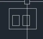
- In the absolute coardinate system the following steps should be followed as a procedure. At first open the autocad and set dimensions that the dimensions are in mm.
- Then enter the Line command in autocad and after that enter the first point of the given diagram as (2,1) that line should be started at the point (2,1) in the coardinate system.
- From that point enter the dimensions of 9 units along x- axis that given in the dimensions and y- axis as zero.
- after that from that point enter the dimensions 6 along the y- axis and X - axis as 0 then the another line is generated.
- contionously take the dimensions of X-axis as -9 and y-axis as 0 to get the anpther point in the coardinate axis.
- from that point take the x- axis as 0 and y-axis as -6 to get the another point of the line in that coardinate system.
- from that point next in x- axis as 3 and y-axis as 2 to get the another end.
- from that point next in x- axis as 2 and y-axis as 0 to get the another end.
- from that point next in x- axis as 0 and y-axis as 3 to get the another end
- from that point next in x- axis as -2 and y-axis as 0 to get the another end
- from that point next in x- axis as 0 and y-axis as -3 to get the another end
- from that we have a option called close point to get the end point.
- copy the object and place it after 1 unit in dimension.

- In the absolute coardinate system the following steps should be followed as a procedure. At first open the autocad and set dimensions that the dimensions are in mm.
- Then enter the Line command in autocad and after that enter the first point of the given diagram as (0,0) that line should be started at the point (0,0) in the coardinate system.
- From that point enter the dimensions of 10 units along X- axis that given in the dimensions and Y- axis as zero.
- after that from that point enter the dimensions 2 along the y- axis and X - axis as zero then the another line is generated.
- contionously take the dimensions of X-axis as -4 and y-axis as 0 to get the anpther point in the coardinate axis.
- from that point take the x- axis as 0 and y-axis as 4 to get the another point of the line in that coardinate system.
- from that point next in x- axis as 3 and y-axis as 0 to get the another end.
- from that point next in x- axis as 0 and y-axis as 2 to get the another end.
- from that point next in x- axis as -8 and y-axis as 0 to get the another end
- from that point next in x- axis as 0 and y-axis as -2 to get the another end
- from that point next in x- axis as 3 and y-axis as 0 to get the another end
- from that point next in x- axis as 0 and y-axis as -4 to get the another end
- from that point next in x- axis as -4 and y-axis as 0 to get the another end
- from that we have a option called close point to get the end point.

- In the absolute coardinate system the following steps should be followed as a procedure. At first open the autocad and set dimensions that the dimensions are in mm.
- Then enter the Line command in autocad and after that enter the first point of the given diagram as (1,1) that line should be started at the point (1,1) in the coardinate system.
- From that point enter the dimensions of 5 units along X- axis that given in the dimensions and Y- axis as zero.
- after that from that point enter the dimensions 2 along the y- axis and X - axis as zero then the another line is generated.
- contionously take the dimensions of X-axis as -3 and y-axis as 0 to get the anpther point in the coardinate axis.
- from that point take the x- axis as 0 and y-axis as -1 to get the another point of the line in that coardinate system.
- from that point next in x- axis as -1 and y-axis as 0 to get the another end.
- from that point next in x- axis as 0 and y-axis as 2 to get the another end.
- from that point next in x- axis as 3 and y-axis as 0 to get the another end
- from that point next in x- axis as 0 and y-axis as 2 to get the another end
- from that point next in x- axis as 3 and y-axis as 0 to get the another end
- from that point next in x- axis as 0 and y-axis as -4 to get the another end
- from that point next in x- axis as -4 and y-axis as 2 to get the another end
- from that we have a option called close point to get the end point.

- In the absolute coardinate system the following steps should be followed as a procedure. At first open the autocad and set dimensions that the dimensions are in mm.
- Then enter the Line command in autocad and after that enter the first point of the given diagram as (1,1) that line should be started at the point (1,1) in the coardinate system.
- From that point enter the dimensions of 2 units along X- axis that given in the dimensions and Y- axis as zero.
- after that from that point enter the dimensions 3 along the y- axis and X - axis as zero then the another line is generated.
- contionously take the dimensions of X-axis as 3 and y-axis as 0 to get the anpther point in the coardinate axis.
- from that point take the x- axis as 0 and y-axis as 4 to get the another point of the line in that coardinate system.
- from that point next in x- axis as -5 and y-axis as 0 to get the another end.
- from that we have a option called close point to get the end point.
- The point axis set point in x- axis as 1 and y-axis as 3 after taking the line command.
- from that point next in x- axis as 3 and y-axis as 0 to get the another end
- from that point next in x- axis as 0 and y-axis as 3 to get the another end
- from that point next in x- axis as -3 and y-axis as 0 to get the another end
- from that we have a option called close point to get the end point.

- In this the following steps should be followed as a procedure. At first open the autocad and set dimensions that the dimensions are in mm.
- Then enter the Line command in autocad and after that enter the first point of the given diagram as (0,0) that line should be started at the point (0,0) in the coardinate system.
- From that point enter the dimensions of 10.00 units along X- axis that given in the dimensions and Y- axis as zero.
- after that from that point enter the dimensions 1 along the y- axis and X - axis as zero then the another line is generated.
- contionously take the dimensions of X-axis as -2 and y-axis as 0 to get the anpther point in the coardinate axis.
- from that point take the x- axis as 0 and y-axis as 4 to get the another point of the line in that coardinate system.
- from that point next in x- axis as 2 and y-axis as 0 to get the another end.
- The point axis set point in x- axis as 0 and y-axis as 1 after taking the line command.
- from that point next in x- axis as 5.381 and at an angle of 120.986 to get the another end
- from that point next in x- axis as 5.931 and at an angle 119.072 get the another end
- from that point next in x- axis as 2 and y-axis as 0 to get the another end
- from that point next in x- axis as 0 and y-axis as -5 to get the another end
- from that point next in x- axis as -2 and y-axis as 0 to get the another end
- from that we have a option called close point to get the end point.
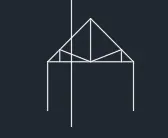
- In this the following steps should be followed as a procedure. At first open the autocad and set dimensions that the dimensions are in mm.
- Then enter the Line command in autocad and after that enter the first point of the given diagram as (1,1) that line should be started at the point (1,1) in the coardinate system.
- From that point enter the dimensions of 0 units along X- axis that given in the dimensions and Y- axis as 4.
- after that from that point enter the dimensions 1 along the x- axis and y - axis as zero then the another line is generated.
- contionously take the dimensions of X-axis as 2.536 and y-axis as 0 to get the anpther point in the coardinate axis.
- from that point take the x- axis as 2.536 and y-axis as 0 to get the another point of the line in that coardinate system.
- from that point next in x- axis as 1 and y-axis as 0 to get the another end and.
- from that point next in x- axis as 5.00 and at an angle of 135 to get the another end
- from starting point next in x- axis as 5.931 and at an angle 45 get the another end
- and draw the mid lines using line command.
- from that we have a option called close point to get the end point.
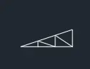
- In this the following steps should be followed as a procedure. At first open the autocad and set dimensions that the dimensions are in mm.
- Then enter the Line command in autocad and after that enter the first point of the given diagram as (1,1) that line should be started at the point (1,1) in the coardinate system.
- From that point enter the dimensions of 2 units along X- axis that given in the dimensions and Y- axis as 0.
- after that from that point enter the dimensions 2 along the x- axis and y - axis as zero then the another line is generated.
- contionously take the dimensions of X-axis as 2 and y-axis as 0 to get the anpther point in the coardinate axis.
- from that point take the x- axis as 2 and y-axis as 0 to get the another point of the line in that coardinate system.
- from that we have a option called close point to get the end point.
- and draw the mid lines using line command.
- from that we have a option called close point to get the end point.