Drafting of various geometries using Chamfer, Fillet tool in AutoCad
Q1.

Aim: To draw a given diagram using autocad
procedure: The following steps should be followed as a procedure to draw a given diagram using autocad
- To draw the given diagram in autocad, the following steps should be followed as a procedure. At first open the AutoCAD and set dimensions that the dimensions are in mm.
- Then enter the Line command in AutoCAD and after that enter the first point of the given diagram as that line should be started at the point in the coordinate system.
- From that point enter the dimensions of 3 units along X- axis that given in the dimensions and Y- axis as zero.
- after that from that point enter the dimensions 2.12 along the axis at an angle 135 degrees to the given line.
- after that from that point enter the dimensions 2.83 along the axis at an angle 90 degrees to the given line.
- from that point take the x- axis as -2 and y-axis as 0 to get another point of the line in that coordinate system.
- from that we have an option called close point or from that point take the x-axis s 0 and y-axis as -6 to get the end point.
- next set the point x axis 1.50 and y axis 1.00 and this point as center draw a circle of diameter as 1.20 and after this from the bottom line as a distence of 2.50 and this point as centre draw a another circle to get the another as per the required figure.
2Q.
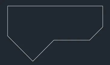
Aim: To draw a given diagram using autocad
procedure: The following steps should be followed as a procedure to draw a given diagram using autocad
- To draw the given diagram in autocad, the following steps should be followed as a procedure. At first open the AutoCAD and set dimensions that the dimensions are in feets and inches.
- Then enter the Line command in AutoCAD and after that enter the first point of the given diagram as that line should be started at the point in the coordinate system.
- From that point enter the dimensions of 8 feets units along X- axis that given in the dimensions and Y- axis as zero.
- from that point take the x- axis as 0 and along the -ve y-axis as 1' 9" to get another point of the line in that coordinate system
- after that from that point enter the dimensions 2' 10" along the axis at an angle 85 degrees to the given line.
- continuously take the dimensions
- after that from that point enter the dimensions 2'6" along the axis at an angle 195 degrees to the given line.
- from that we have an option called close point or from that point take the x-axis s 0 and y-axis as -6 to get the end point.
3Q.
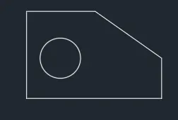
Aim: To draw a given diagram using autocad
procedure: The following steps should be followed as a procedure to draw a given diagram using autocad
- To draw the given diagram in autocad, the following steps should be followed as a procedure. At first open the AutoCAD and set dimensions that the dimensions are in feets and inches.
- Then enter the Line command in AutoCAD and after that enter the first point of the given diagram as that line should be started at the point in the coordinate system.
- From that point enter the dimensions of 5'0.1" units along X- axis that given in the dimensions and Y- axis as zero.
- From that point enter the dimensions of 0 units along X- axis that given in the dimensions and Y- axis as 1'6".
- after that from the starting point enter the dimensions 3'3" along the axis and Y- axis as zero.
- From that point enter the dimensions of 2'6.5" units along X- axis that given in the dimensions and Y- axis as 0.
- from that we have an option called close point or from that point take the x-axis s 0 and y-axis as -6 to get the end point.
4Q.
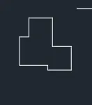
Aim: To draw a given diagram using autocad
procedure: The following steps should be followed as a procedure to draw a given diagram using autocad
- To draw the given diagram in autocad, the following steps should be followed as a procedure. At first open the AutoCAD and set dimensions that the dimensions are in mm.
- Then enter the Line command in AutoCAD and after that enter the first point of the given diagram as that line should be started at the point in the coordinate system.
- From that point enter the dimensions of 3 units along X- axis that given in the dimensions and Y- axis as zero.
- From that point enter the dimensions of 0 units along X- axis that given in the dimensions and Y- axis as 0.50.
- From that point enter the dimensions of 2.50 units along X- axis that given in the dimensions and Y- axis as zero
- From that point enter the dimensions of 0 units along X- axis that given in the dimensions and Y- axis as 2.50.
- from that point take the x- axis as -2 and y-axis as 0 to get another point of the line in that coordinate system.
- from that point take the x- axis as -2.50 and y-axis as 0 to get another point of the line in that coordinate system.
- from that point take the x- axis as 0 and y-axis as -2 to get another point of the line in that coordinate system
- from that point take the x- axis as -1 and y-axis as 0 to get another point of the line in that coordinate system
- from that we have an option called close point or from that point take the x-axis s 0 and y-axis as -6 to get the end point as per the required figure.
5Q.
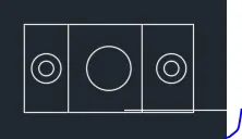
Aim: To draw a given diagram using autocad
procedure: The following steps should be followed as a procedure to draw a given diagram using autocad
- To draw the given diagram in autocad, the following steps should be followed as a procedure. At first open the AutoCAD and set dimensions that the dimensions are in mm.
- Then enter the Line command in AutoCAD and after that enter the first point of the given diagram as that line should be started at the point in the coordinate system.
- From that point enter the dimensions of 11.50 units along X- axis that given in the dimensions and Y- axis as zero.
- From that point enter the dimensions of 0 units along X- axis that given in the dimensions and Y- axis as 11.50.
- From that point enter the dimensions of -11.50 units along X- axis that given in the dimensions and Y- axis as zero.
- from that we have an option called close point or from that point take the x-axis s 0 and y-axis as -6 to get the end point.
- next set the point x axis 1.50 and y axis 3.00 and this point as center draw a circle of diameter as 2.00 and after this same point as a centre draw a another circle of diameter 1.00 to get the another as per the required figure.
- next set the point x axis 10 and y axis 3.00 and this point as center draw a circle of diameter as 2.00 and after this same point as a centre draw a another circle of diameter 1.00 to get the another as per the required figure.
- next set the point x axis 5.75 and y axis 3.00 and this point as center draw a circle of diameter as 3.00 to get the another as per the required diagram.
6Q.

Aim: To draw a given diagram using autocad
procedure: The following steps should be followed as a procedure to draw a given diagram using autocad
- To draw the given diagram in autocad, the following steps should be followed as a procedure. At first open the AutoCAD and set dimensions that the dimensions are in mm.
- Then enter the Line command in AutoCAD and after that enter the first point of the given diagram as that line should be started at the point in the coordinate system.
- From that point enter the dimensions of 2.50 units along X- axis that given in the dimensions and Y- axis as zero.
- From that point enter the dimensions of 0 units along X- axis that given in the dimensions and Y- axis as 1.5.
- From that point enter the dimensions of 0 units along X- axis that given in the dimensions and Y- axis as 0.5.
- From that point enter the dimensions of 0 units along X- axis that given in the dimensions and Y- axis as -1.
- From that point enter the dimensions of -1.5 units along X- axis that given in the dimensions and Y- axis as 0.
- from that we have an option called close point or from that point take the x-axis s 0 and y-axis as -0.5 to get the end point.
- From that point enter the dimensions of 1.50 units along X- axis that given in the dimensions and Y- axis as zero.
- From that point enter the dimensions of 0 units along X- axis that given in the dimensions and Y- axis as 0.5.
- From that point enter the dimensions of 0.5 units along X- axis that given in the dimensions and Y- axis as 0 repeat this three times and draw the lines to close the figure.
- From that point enter the dimensions of 2.0 units along X- axis that given in the dimensions and Y- axis as 0.
- From that point enter the dimensions of 0.5 units along X- axis that given in the dimensions and Y- axis as 0 repeat this three times and draw the lines to close the figure.
- Then colse all the lines using the line command and then to make it the complete figure as per the required diagram.
7Q.
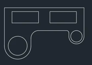
Aim: To draw a given diagram using autocad
procedure: The following steps should be followed as a procedure to draw a given diagram using autocad
- To draw the given diagram in autocad, the following steps should be followed as a procedure. At first open the AutoCAD and set dimensions that the dimensions are in mm.
- Then enter the Line command in AutoCAD and after that enter the first point of the given diagram as that line should be started at the point in the coordinate system.
- first set the point along the coordiate sytem and this point as center draw a circle of diameter as 50.00 and after this same point as a centre draw a another circle of diameter 70.00 another as per the required diagram.
- From that point tangent to the circle enter the dimensions of 0 units along X- axis that given in the dimensions and Y- axis as 100.
- From that point enter the dimensions of 210 units along X- axis that given in the dimensions and Y- axis as zero.
- From that point enter the dimensions of 0 units along X- axis that given in the dimensions and Y- axis as -75.
- next set the line x axis 20 and this point as center draw a circle of diameter as 30.00 and after this same point as a centre draw a another circle of diameter 50.00 to get the another as per the required figure trim the extra lines.
- use the fillet option in the autocad and then select the lines and the radius as 20 and 6 draw the fillet to that lines.
- From that line as a dis tence of 20 in the +ve x axis as that point as a center draw a rectangle of length is 70 and width is 30 and then copy that rectangle using the copy command in the auocad and then place it in the distence of 30 in the +ve x axis direction to get the required diagram.
8Q.

Aim: To draw a given diagram using autocad
procedure: The following steps should be followed as a procedure to draw a given diagram using autocad
- To draw the given diagram in autocad, the following steps should be followed as a procedure. At first open the AutoCAD and set dimensions that the dimensions are in mm.
- Then enter the Line command in AutoCAD and after that enter the first point of the given diagram as that line should be started at the point in the coordinate system.
- first set the point along the coordiate sytem and this point as center draw a circle of diameter as 0.90 and after this same point as a centre draw a another circle of diameter 1.80 another as per the required diagram.
- next at a distence of 4.275 from the center of that circle draw a another point and this point as center draw a circle of diameter as 5 and after this same point as a centre draw a another circle of diameter 4.00 another as per the required diagram.
- next at a distence of 8.55 from the center of that circle draw a another point and this point as center draw a circle of diameter as 0.90 and after this same point as a centre draw a another circle of diameter 1.80 another as per the required diagram.
- from that circles draw the lines which are tangent to each other circles and then trim the extra lines as per the required diagram.
9Q.
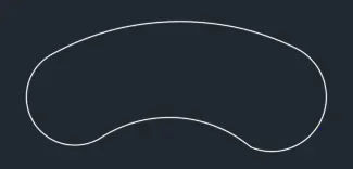
Aim: To draw a given diagram using autocad
procedure: The following steps should be followed as a procedure to draw a given diagram using autocad
- To draw the given diagram in autocad, the following steps should be followed as a procedure. At first open the AutoCAD and set dimensions that the dimensions are in feets and inches.
- Then enter the Line command in AutoCAD and after that enter the first point of the given diagram as that line should be started at the point in the coordinate system.
- first set the point along the coordiate sytem and this point as center draw a circle of diameter as 8' and after this from that point 32'6" along the +ve x axis centre draw a another circle of diameter 9' another as per the required diagram.
- Draw a circle using the option in autocad as tangent tangent center as a option draw a circle as radius 20'10" and then trim the extra lines as per the required diagram.
- Draw a circle using the option in autocad as tangent tangent center as a option draw a circle as radius 41'8" and then trim the extra lines as per the required diagram.
10Q.

Aim: To draw a given diagram using autocad
procedure: The following steps should be followed as a procedure to draw a given diagram using autocad
- To draw the given diagram in autocad, the following steps should be followed as a procedure. At first open the AutoCAD and set dimensions that the dimensions are in feets and inches.
- Then enter the Line command in AutoCAD and after that enter the first point of the given diagram as that line should be started at the point in the coordinate system.
- from that draw a rectangle using the rectangle command in the autocad and then make offset to that rectangle.
- copy that rectangle through the center and then rotate the rectangle at an angle of 90 degrees thorugh the center.
- and then move that rectangle and place it same point of recantangle through the centre and then we gte the required diagram.
11Q.

Aim: To draw a given diagram using autocad
procedure: The following steps should be followed as a procedure to draw a given diagram using autocad
- To draw the given diagram in autocad, the following steps should be followed as a procedure. At first open the AutoCAD and set dimensions that the dimensions are in feets and inches.
- Then enter the Line command in AutoCAD and after that enter the first point of the given diagram as that line should be started at the point in the coordinate system.
- from that point draw a rectangle using the rectangle command in the autocad using the dimensions of a rectangle as the length of a rectangle is 20'4" and the width of it is 13'6".
- from the top of the line of rectangle draw a line 9' down through the -ve y axis and then 3' in the -ve x axis and then 4'6" in the -ve y axis and next 4'6" in the -ve x axis and 0.5 in the +ve y axis 4'6" in the -ve x axis 4'6" in the +ve y axis and then close it by the end point and then trim the unwanted lines using the trim option in the autocad.
- from the top of the line of rectangle draw a line 3' down through the -ve y axis and 3'7" at an angle of 60 degrees and then at a distence of 12'8" at an angle of 90 degrees close it by the end point and then trim the unwanted lines using the trim option in the autocad.
- from that point 5'11" along the y axis and then 10'2" along the x axis and this point as a centre draw a rectangle using the rectangle command in the autocad using the dimensions of a rectangle as the length of a rectangle is 3' and the width of it is 3' and rotate the rectangle at an angle of 90 degrees throuth the center of rectangle to get the required diagram.