Creating a Floor plan, Footing detail and Isometric view using AutoCad
Q1.
Aim: Draw the given column cross section using autocad.
Procedure: The detail step by step procedure to draw the given cross section of column using autocad are:
- At first open the autocad and set dimensions that the dimensions.
- for drawing the column first use the rectangle command called rec enter and select the point and then after we have a option called dimensions in that we enter the dimensions of lenghth is 0.90 and the width of rectangle is 0.25.
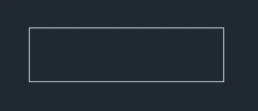
- from the center of the given line that the settings can be made in the option of osnap then from the centre we can draw the line half of the length of the another ie 0.20 from that draw a rectangle using the rectangle command.
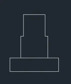
- repeat the same process again for the next level of the column which is given in that dimensons to get the rquired shape of the column.
- and trim the extra lines which is not required using trim command ie tr double enter and erase the lines which are not required.
- from the corner left point draw the rectangle using the rectangle command and the select the point of let side and then enter the option called dimensions for the entering the dimensions of rectangle as length is eaual to 1.15 and width is equal to 0.15.
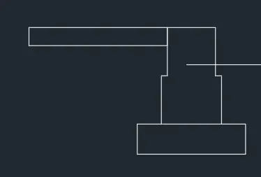
- next we should draw the required lines using the line command and the select the left corner point of the rectangle and then draw the first line using line command and then show the direction in +ve x-axis and then enter the value as 0.30 next show the direction in +ve y-axis and the enter the value as 0.15 and then repeat the process for three times to get the required shape as given in the figure below.
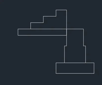
- next from the center to the both ends that taking the point through from the center of the rectangle draw the another rectangle using the command of rectangle and then enter the dimensions of the rectangle as length is equal to 0.30 and width is equal to 0.60 and then we can get the required shape as given below.
- from that point we can take the another line using the line command and then from the +ve y direction enter the value as 0.50 and then +x-axis enter the value as 0.30 and then close the line.
- and then from that point draw the line using the line command and then from the point pointing through the +ve y axis draw the line using line command and then repat the line by pointing throught the -ve x-axis and the value as 0.30 and then down to the -ve yaxis point out throgh that point enter the value -1 in dimension.
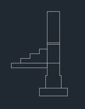
- Trim the lines which is not required using the trim command.
2Q.
Aim: Draw the given column cross section using autocad.
Procedure: The detail step by step procedure to draw the given cross section of column using autocad are:
- At first open the autocad and set dimensions that the dimensions.
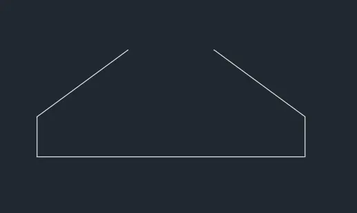
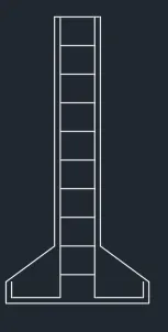
- for drawing the column first use the line command called L enter and select the point and then after we pointing through the +ve x- axis direction enter the value as 1.0 and then after that pointing through the +ve y-axis enter the value as 0.15.
- and then press esc to exit the command and then use line command point through the starting and showing the direction + ve y axis enter the dimension of 0.15.
- and from that point using the line command enter the value of x is 0.34 and y as 0.25 to get the required dirction and same repeat the line command in the another direction point side but in the - x direction ie the value of x axis is -0.34 and the y is 0.25.
- form the end point using the line command towards the direction of +ve y axis enter the value as 1.60 and then from that point -ve x- axis enter the value as the 0.32 and then pointong through the -ve y axis enter the value as 1.60 to get the required shape as shown in the figure below.
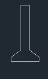
- from that point and next take the offset command and then it will tell that to enter the value as 0.04 as the dimension and then offset the line both in the lines and then bottom line and sides of the bottom line by that we can get the required shape as given in the figure below.
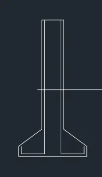
- from the secound left side corner by using the line command below the -ve y axis enter the value as 0.20 and then forn that point in the positive x axis enter the value as 0.24 to get the required line repeat the line by using the copy command and then copy the line ans paste it by using the space between the lines as 0.20 and repeat the process until you get the required shape of given dimensions then you will get the required shape as shpwn in figure below.
3Q.
Aim: Draw the given floor plan cross section using autocad.
Procedure: The detail step by step procedure to draw the given floor plan using autocad are:
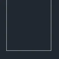
- To draw the given floor plan we should use the line command and then from the +ve x- direction use the value as 3.60 and then from that + ve y direction using the vakue as 4.20 and from that point in the direction of -ve x axis enter the value as 3.60 and then use the option called close the line so that we can get the required diagram and then delete the unwanted lines we can the shape as shown in the figure below.
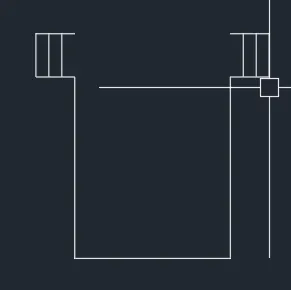
- next we should use the line command and then from the -ve x- direction use the value as 0.90 and then from that + ve y direction using the vakue as 1 and from that point in the direction of +ve x axis enter the value as 0.90 and then use the option called close the line so that we can get the required diagram and then delete the unwanted lines and draw the lines in the -ve x axis and by spacing between the lines as 0.30 and then we can the shape as shown in the figure below.
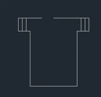
- Draw the line using the line command and then enter the value as 0.90 in the +ve x direction and then draw the line in the next side using the line command 1.80 as dimension we can the shape as shown in the figure below.
- from the left side point by using the line command in the + ve y direction and the value as the 3.60 draw the line and in the direction of + ve x direction use the value as 3.60 and then in the direction of - ve y direction use the value as 3.60 get the required shape of floor plan given dimensions then you will get the required shape as shpwn in figure below.

4Q.
Aim: Draw the given column cross section using autocad.
Procedure: The detail step by step procedure to draw the given cross section of column using autocad are:
- At first open the autocad and set dimensions that the dimensions.
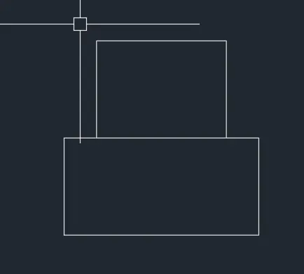
- for drawing the column first use the rectangle command called rec enter and select the point and then after we have a option called dimensions in that we enter the dimensions of lenghth is 0.90 and the width of rectangle is 0.45.
- Then from the center of the rectangle drwan to the left as 0.25 from the center enter the line command and from the +ve y axis direction enter the value as 0.40 in the direction of +ve x axis enter the value 0.50 or draw the rectangle from the point where the center to 0.25 point form that enter the value as dimensions as length is 0.50 and width as 0.40 then we get the required shape as given in the figure below and trim the unnessary lines by using the trim command.
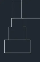
- Then from the center of the rectangle drwan to the left as 0.20 from the center enter the line command and from the +ve y axis direction enter the value as 0.30 in the direction of +ve x axis enter the value 0.50 or draw the rectangle from the point where the center to 0.20 point form that enter the value as dimensions as length is 0.50 and width as 0.30 then we get the required shape.
- repat the process Then from the center of the rectangle drwan to the left as 0.15 from the center enter the line command and from the +ve y axis direction enter the value as 0.60 in the direction of +ve x axis enter the value 0.30 or draw the rectangle from the point where the center to 0.20 point form that enter the value as dimensions as length is 0.30 and width as 0.60 then we get the required shape as given in the figure below and trim the unnessary lines by using the trim command.
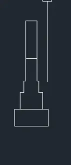
- from that point enter the value as the 1 in the +ve y direction using the line command and then from that +ve x axis from the value as 0.30 in the direction and then 1 in the - ve y direction to get the required shape as shown in the figure below.
5Q. Isometric drawings:
Aim:
Draw the given Isometric drawing using autocad.
Procedure: The detail step by step procedure to draw the given cross section of a Isometric drawing using autocad are:
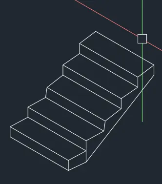
- set the autocad settings in the Isometric view as snapsettings as a required dimensions and then use the line command and then set the direction towards the required way and then set the values
- for the given figure or diagram use line command and then on the ortho so that we can gte the required straight line and then draw the line of 1' using the line command
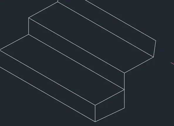
- and then next put the point towards the the 90 degress ie towards up direction and then set the value as 0.15 and then towards the line parllel to the line draw another line of 1' and again draw the line of 0.30 in the required direction.
- repeat the process for 5 times to get the required diagram and then at last connect the line end point to the starting point to gte the required diagram as shown in the figure below.
6Q.
Draw the given Isometric drawing using autocad.
Procedure: The detail step by step procedure to draw the given cross section of a Isometric drawing using autocad are:
- set the autocad settings in the Isometric view as snapsettings as a required dimensions and then use the line command and then set the direction towards the required way and then set the values
- for the given figure or diagram use line command and then on the ortho so that we can gte the required straight line and then draw the line of 0.30' using the line command.
- and then next put the point towards the the 90 degress ie towards up direction and then set the value as 3 and then towards the line parllel to the line draw another line of 2.42 and again draw the line of 1.00 in the required direction.
- and then next put the point towards the degress ie towards up direction and then set the value as 3 and then towards the line parllel to the line draw another line of 0.30 and again draw the line of 1.00 in the required direction.
- and then next put the point towards the ie towards up direction and then set the value as 0.30 and then towards the line parllel to the line draw another line of 2.42 and again draw the line of 1.00 in the required direction to get the required diagram and then at last connect the line end point to the starting point to gte the required diagram as shown in the figure below.