Project 2 - Rankine cycle Simulator
Rankine cycle Simulator
1. OBJECTIVES:
1) To Develop a basic program that calculates the state points
2) To add the thermodynamic relation to get the points inbetween the state variables.
3) To plot rankine cycle on T-s and H-s curve.
2.THEORY:-
The Rankine cycle is the fundamental operating cycle of all power plants where an operating fluid is continuously evaporated and condensed. The selection of operating fluid depends mainly on the available temperature range.
The Rankine cycle operates in the following steps:
-
1-2-3 Isobaric Heat Transfer. High pressure liquid enters the boiler from the feed pump (1) and is heated to the saturation temperature (2). Further addition of energy causes evaporation of the liquid until it is fully converted to saturated steam (3).
-
3-4 Isentropic Expansion. The vapor is expanded in the turbine, thus producing work which may be converted to electricity. In practice, the expansion is limited by the temperature of the cooling medium and by the erosion of the turbine blades by liquid entrainment in the vapor stream as the process moves further into the two-phase region. Exit vapor qualities should be greater than 90%.
-
4-5 Isobaric Heat Rejection. The vapor-liquid mixture leaving the turbine (4) is condensed at low pressure, usually in a surface condenser using cooling water. In well designed and maintained condensers, the pressure of the vapor is well below atmospheric pressure, approaching the saturation pressure of the operating fluid at the cooling water temperature.
-
5-1 Isentropic Compression. The pressure of the condensate is raised in the feed pump. Because of the low specific volume of liquids, the pump work is relatively small and often neglected in thermodynamic calculations.
-
The Rankine cycle is used in power plants because it efficiently converts heat into mechanical work, which can then be used to generate electricity. Here's a brief overview of how it works:
- Water is pumped to high pressure (1-2) before entering the boiler.
- In the boiler, the water is heated and turns into high-pressure steam (2-3).
- The high-pressure steam is expanded in a turbine, producing mechanical work (3-4).
- The low-pressure steam exiting the turbine is condensed back into water in a condenser (4-1).
- The cycle repeats.
By repeating this cycle, heat from an external source (often fueled by coal, natural gas, nuclear, or renewable sources) is converted into mechanical work, which is then used to generate electricity through a generator. The Rankine cycle is a practical way to harness thermal energy and convert it into useful work for power generation. It is the basis for the operation of most steam power plants and is widely used in various industrial applications
- Figure (1) :-
- The Idealized Rankine Cycle
- Figure 2:-
Pressure-Enthalpy (p-h) and Temperature-Entropy (T-s) Diagrams
MATLAB CODE FOR RANKINE CYCLE SIMULATOR--
<![endif]-->
<![endif]-->
<![endif]-->
<![endif]-->
<![endif]-->
<![endif]-->
<![endif]-->
<![endif]-->
<![endif]-->
<![endif]-->
<![endif]-->
<![endif]-->
<![endif]-->
<![endif]-->
<![endif]-->
<![endif]-->
<![endif]-->
<![endif]-->
<![endif]-->
<![endif]-->
<![endif]-->
<![endif]-->
1-3: These lines are used to clear the MATLAB workspace, close all open figures, and clear the command window.
5-9: Display introductory information about the Rankine Cycle Simulator and the various stages of the Rankine cycle.
11-13: Prompt the user to input the pressure at the turbine inlet (p1), temperature at the turbine inlet (t1) and the user to input the pressure at the condenser (p2).
16-18: Calculate the saturation temperature (tsat) at the turbine inlet pressure (p1) using the XSteam library. Also, calculate the specific entropy values for the liquid (sf1) and vapor (sg1) phases at p1.
19-28: Check if the user-entered temperature (t1) is greater than the saturation temperature (tsat). If it is, calculate the enthalpy (h1) and specific entropy (s1) at the turbine inlet conditions. If not, display an error message.
31-38: Calculate various properties at the turbine exhaust conditions (state 2) including temperature (t2), enthalpy of liquid (hf2) and vapor (hg2), specific entropy (s2), specific entropy of the vapor phase (sg2), specific entropy of the liquid phase (sf2), and quality (x2).
41-44: Set the conditions at the condenser exit (state 3) equal to those at the turbine exhaust (state 2) since it is assumed to be an isobaric process.
47-55: Set the conditions at the boiler inlet (state 4) based on the isentropic compression in the pump. Calculate temperature (t4) and specific volume (vf) at state 3 and then calculate the work done by the pump (wp). Finally, calculate enthalpy (h4) at state 4.
57-59: Calculate the work output from the turbine (wt), heat input to the system (Qin), and heat output from the system (Qout).
60-62: Calculate the net work done (wnet) and thermal efficiency (Ntherm) of the Rankine cycle.
64: Calculate specific fuel consumption (ssc).
After that : > Create a T-S (Temperature-Entropy) diagram using MATLAB's plot function. This section of code plots the saturation lines, the process path from state 1 to state 4, and the specific entropy values at different temperatures.
> Create an H-S (Enthalpy-Entropy) diagram. This section of code plots the saturation lines, the process path from state 1 to state 4, and specific enthalpy values at different specific entropy values.
> Output the results of the Rankine cycle simulation, including properties at each state and various cycle parameters like work output, thermal efficiency, and specific fuel consumption.
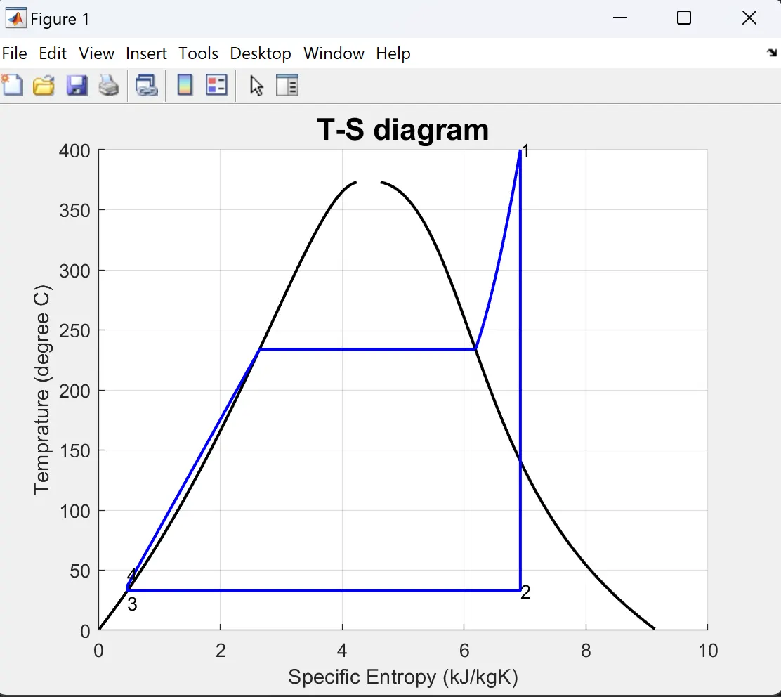
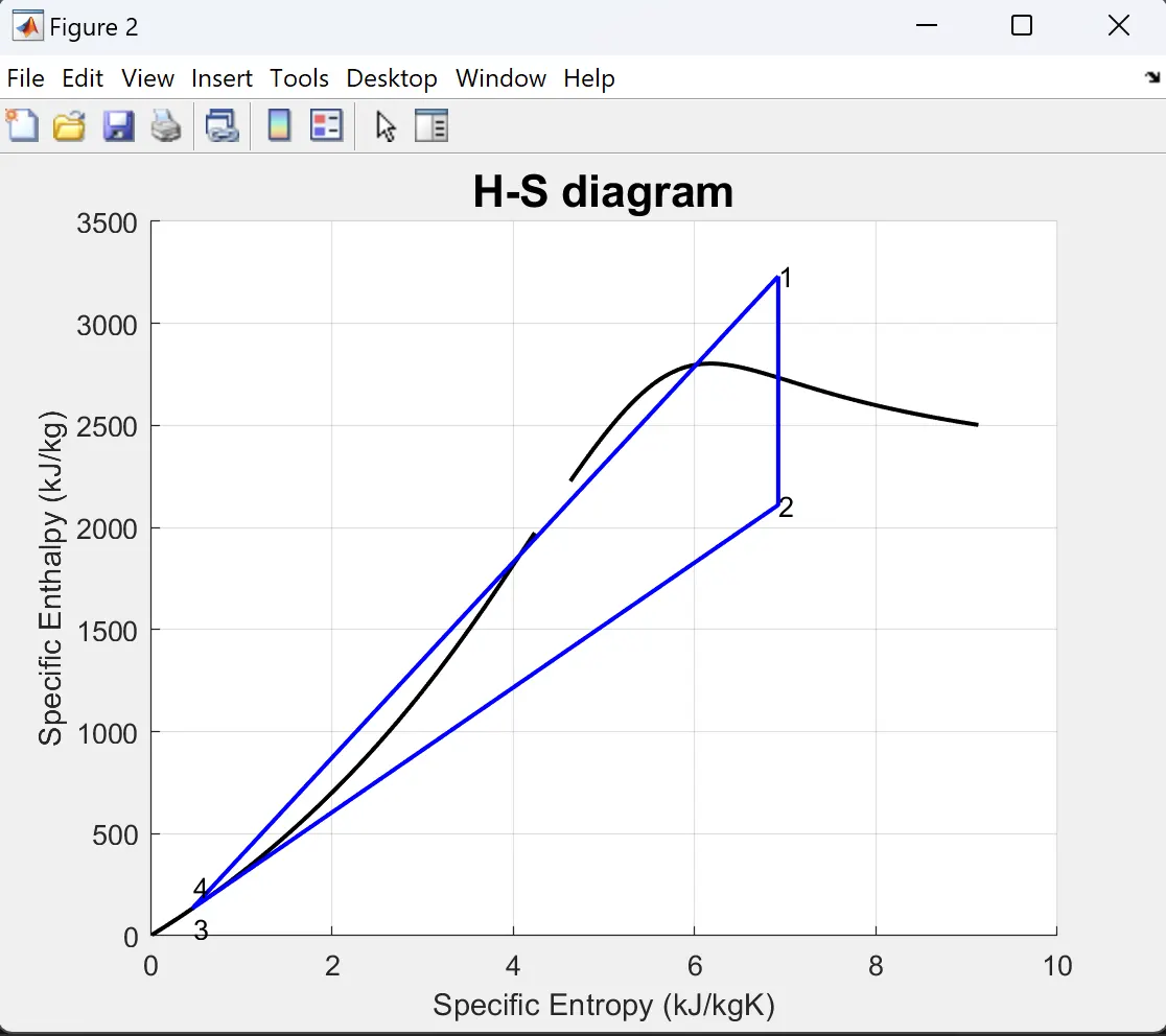
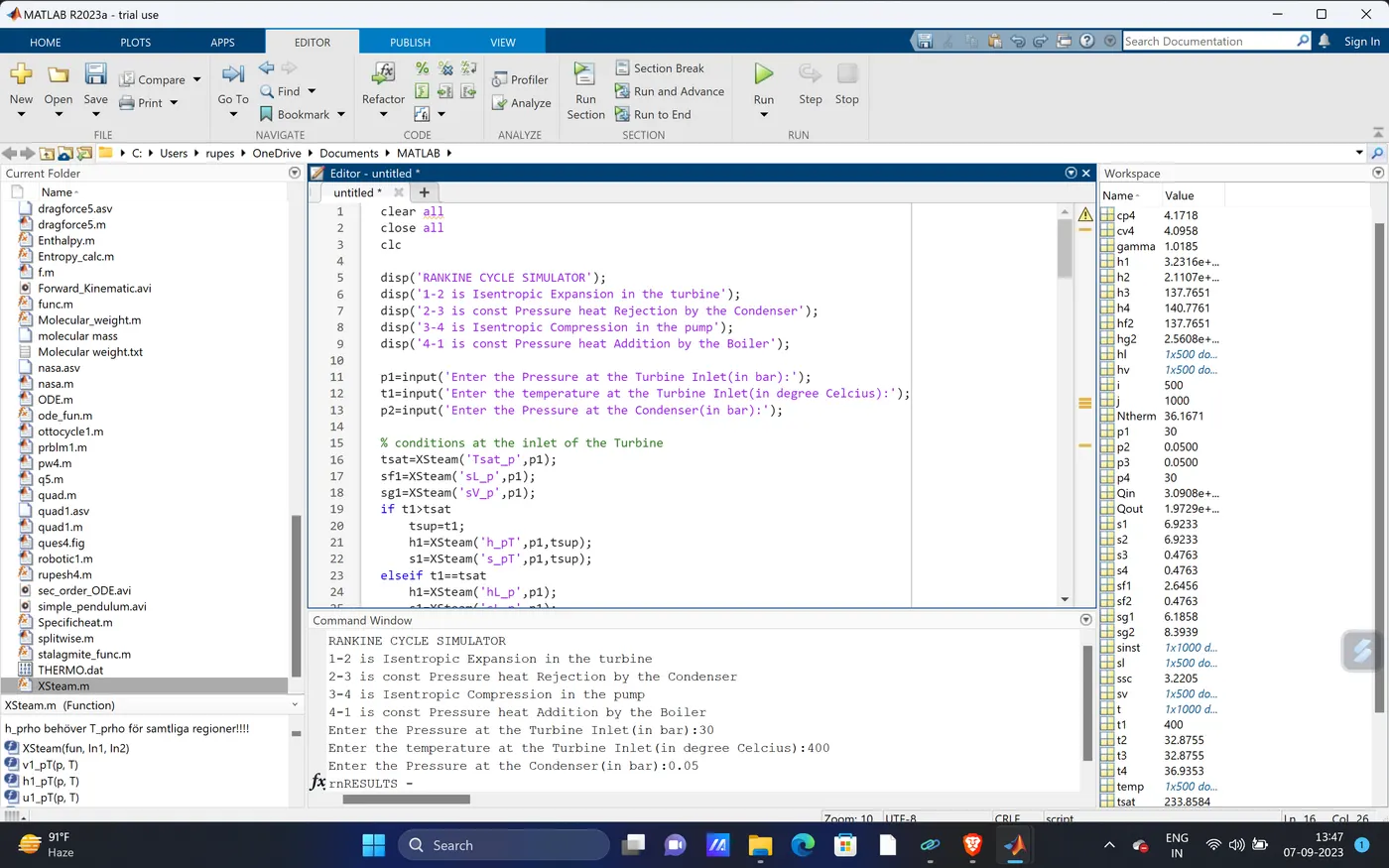
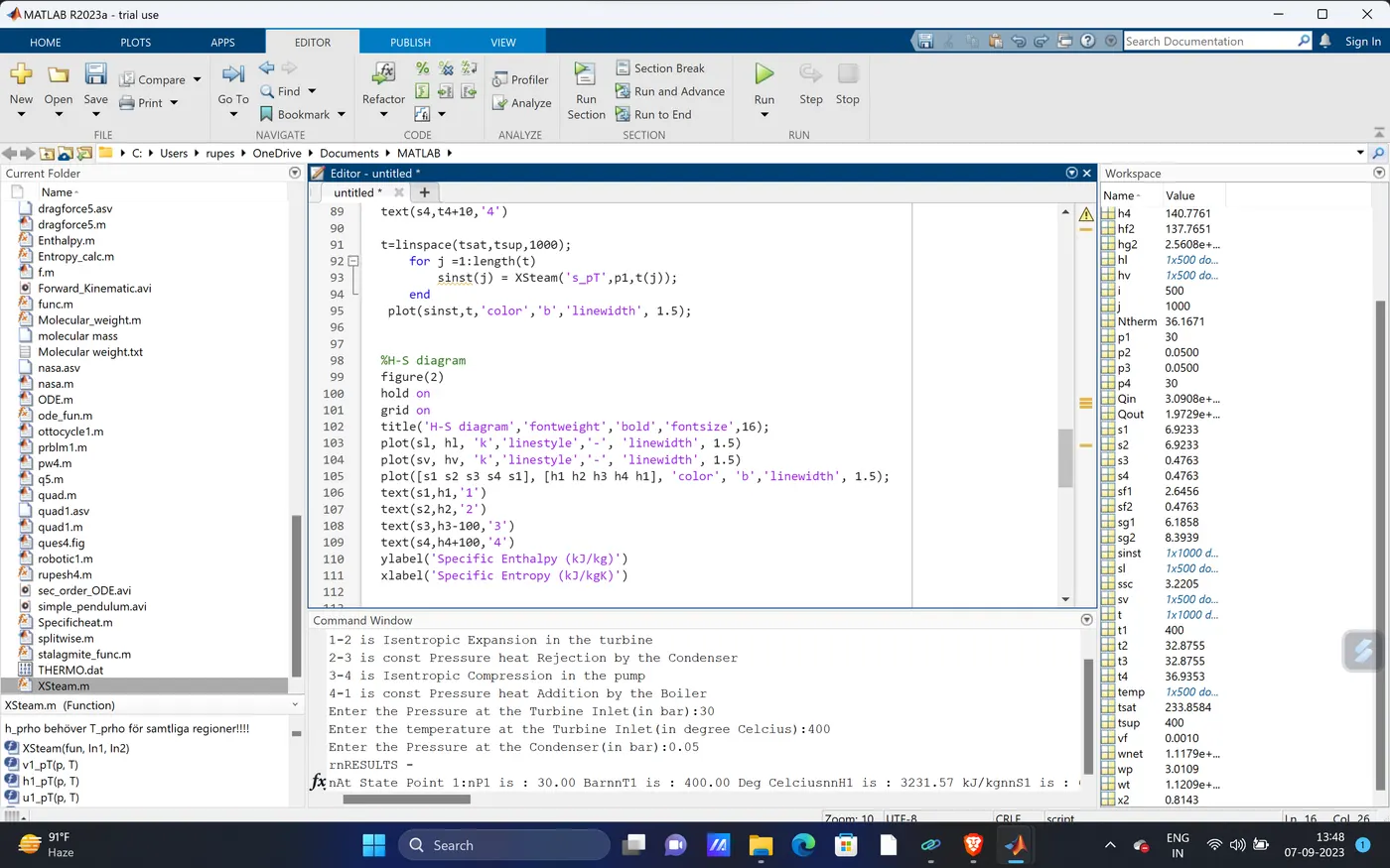
1-2 is Isentropic Expansion in the turbine
2-3 is const Pressure heat Rejection by the Condenser
3-4 is Isentropic Compression in the pump
4-1 is const Pressure heat Addition by the Boiler
Enter the Pressure at the Turbine Inlet(in bar):30
Enter the temperature at the Turbine Inlet(in degree Celcius):400
Enter the Pressure at the Condenser(in bar):0.05
rnRESULTS -
nAt State Point 1:nP1 is : 30.00 BarnnT1 is : 400.00 Deg CelciusnnH1 is : 3231.57 kJ/kgnnS1 is : 6.92 kJ/kgKrnnrnAt State Point 2:nP2 is : 0.05 BarnT2 is : 32.88 Deg CelciusnH2 is : 2110.71 kJ/kgnS2 is : 6.92 kJ/kgKrnnrnAt State Point 3:nP3 is : 0.05 BarnT3 is : 32.88 Deg CelciusnH3 is : 137.77 kJ/kgnS3 is : 0.48 kJ/kgKrnnrnAt State Point 4:nP4 is : 30.00 BarnT4 is : 36.94 Deg CelciusnH4 is : 140.78 kJ/kgnS4 is : 0.48 kJ/kgKrnnrnWt is : 1120.86 kJ/kgnWp is : 3.01 kJ/kgnWnet is : 1117.85 kJ/kgnNtherm is : 36.17 PercentnS.S.C is : 3.22 kg/kWhn>>