Project 2 - Modeling of 3 phase Induction Motor Drive
PROJECT
1. Model 3 Phase Inverter using Simulink (model the parasitic as well) with a switching frequency of 10Khz using 3 phase Squirrel Cage Induction motor, using V/F method, open loop
Design Parameters:
- Power = 100 HP
- DC Voltage = 800 V
- Output Voltage = 460 VRMS – line to line
- Initial Speed = 1500 RPM
- Final Speed = 1000 RPM
- Initial Load Torque = 10 Nm
- Final Torque=20 Nm
- Torque Step Time = 0.1 secs
For Induction Motor model – use Asynchronous Machine from Simulink with Squirrel Cage Preset Model – 05 , for 100HP Motor
For back emf to speed relation, assume a linear rate from 0.25 to 1, with speed changing from 500 RPM to 2000 RPM
Plot speed, stator voltage (line to line) and frequency.
Plot stator line voltage, phase current.
Solution -
AIM -
Model a three-Phase Inverter having a switching frequency of 10Khz using 3 phase Squirrel Cage Induction motor and using the Open loop V/F method with Simulink.
THEORY -
Open Loop V/F Control:
The open loop V/F control of an induction motor is the most common method of speed control because of its simplicity and these types of motors are widely used in industry. Traditionally, induction motors have been used with open loop 50Hz power supplies for constant speed applications. For adjustable speed drive applications, frequency control is natural. However, voltage is required to be proportional to frequency so that the stator flux
Ѱs=Ѵs/ωs
Remains constant if the stator resistance is neglected. The power circuit consists of a diode rectifier with a single or three-phase ac supply, filter, and PWM voltage-fed inverter. Ideally, no feedback signals are required for this control scheme.
The PWM converter is merged with the inverter block. Some problems encountered in the operation of this open loop drive are the following:
The speed of the motor cannot be controlled precisely, because the rotor speed will be slightly less than the synchronous speed, and in this scheme, the stator frequency and hence the synchronous speed is the only control variable.
The slip speed, being the difference between the synchronous speed and the electrical rotor speed, cannot be maintained, as the rotor speed is not measured in this scheme. This can lead to operation in the unstable region of the torque-speed characteristics.
The effect of the above can make the stator currents exceed the rated current by a large amount thus endangering the inverter-converter combination
These problems are to be suppressed by having an outer loop in the induction motor drive, in which the actual rotor speed is compared with its commanded value, and the error is processed through a controller usually a PI controller and a limiter is used to obtain the slip-speed command.
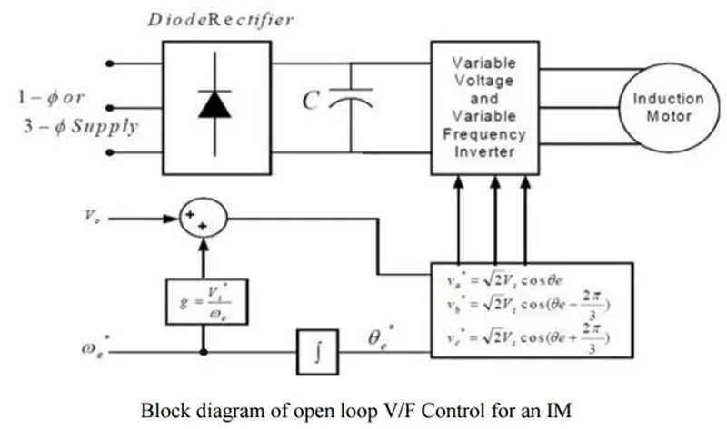
Given design parameters -
- Power = 100 HP
- DC Voltage = 800 V
- Output Voltage = 460 VRMS – line to line
- Initial Speed = 1500 RPM
- Final Speed = 1000 RPM
- Initial Load Torque = 10 Nm
- Final Torque=20 Nm
- Torque Step Time = 0.1 secs
- Switching frequency = 10kHz
SIMULINK MODEL -
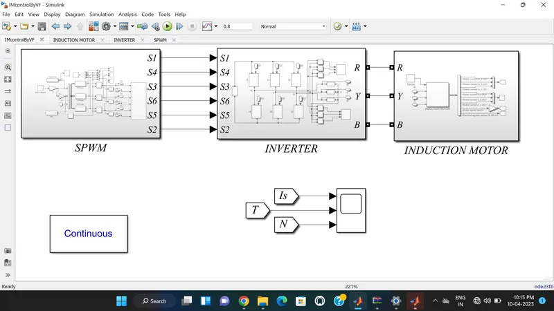
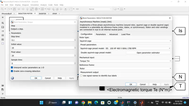
Each Block Property are shown below
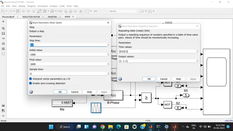
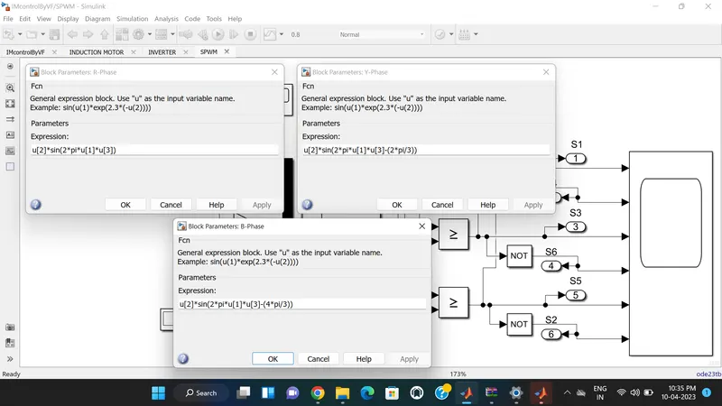
EXPLANATION -
The three-phase inverter using 3 phase squirrel cage induction motor using the v/f method open loop model is built in Simulink.
This model is designed into three parts.
- Spwm (V/f control)
- Three-phase inverter
- Induction motor
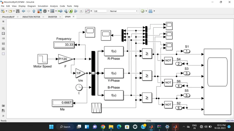
1. SPWM (V/f Control) -
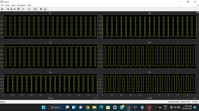
Gate pulses are shown below:
For this SPWM (v/f) control, speed is taken as input in a step block. the step output is given to the gain block to multiply with the p/120.
Ns = (120*f)/P
f = (Ns*P)/120.
By using the above formula frequency is measured. Speed is taken as input in the step block with an initial speed of 1500 rpm and a final of 1000 rpm as given in the design parameters.
For the time input a clock block is used. And these output values are given to a bus selector block.
The bus selector output signal is given to the MATLAB function block and the Three phase voltage is measured by using the below formulae:
Va = Vs sin(2*pi*f*t)
Vb = Vs sin(2*pi*f*t - 2pi/3)
Vc = Vs sin(2*pi*f*t - 4pi/3) or Vs sin(2*pi*f*t + 2pi/3)
By comparing each phase output and repeating sequence with the relational operator the gate signals are generated and a NOT gate is connected to obtained the inverted gate signal then these signals are given to scope to visualize the response.
2. Three-Phase Inverter -
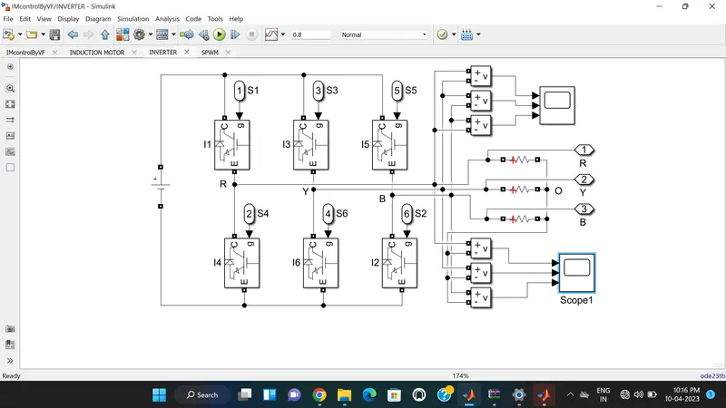
In this subsystem, the DC voltage source is taken as input. And connected to the IGBT switches. Three legs with six IGBT switches are used in this inverter. Each leg has two switches for positive and negative operation. Each leg on the phase is connected to the load. A resistive load is used in this model to measure the line-to-line and phase voltages. And three output connections are taken and then it is applied to Induction motor as an input.
3. Induction Motor -
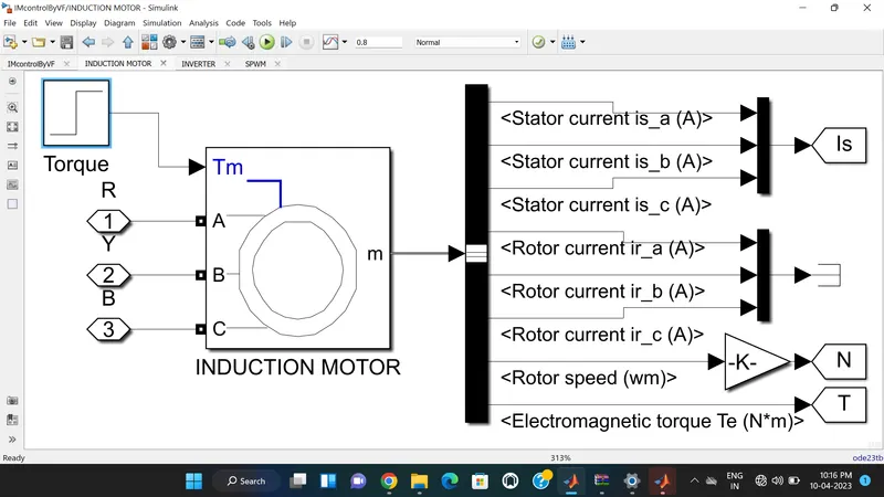
In this subsystem, the induction motor with torque input is observed. Step block is used to apply torque on induction motor.The initial and final torque values are given in the Block.
In the motor block pre-set model, no:5 is taken as mentioned in the project description. To observe the motor stator current, speed, and torque parameters a bus selector block is connected to the Induction motor measurement block and parameters are selected. Then the stator current and torque are given to scope, the rotor speed is multiplied with a gain block 60/2*p to get speed in RPM, and then it is given to scope.
RESULT -
The frequency plot is shown below -
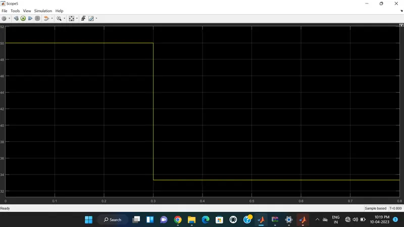
The frequency is starting from 50 Hz and at 0.3 secs the step fall to 33.33 Hz and is constant until 0.8 seconds.
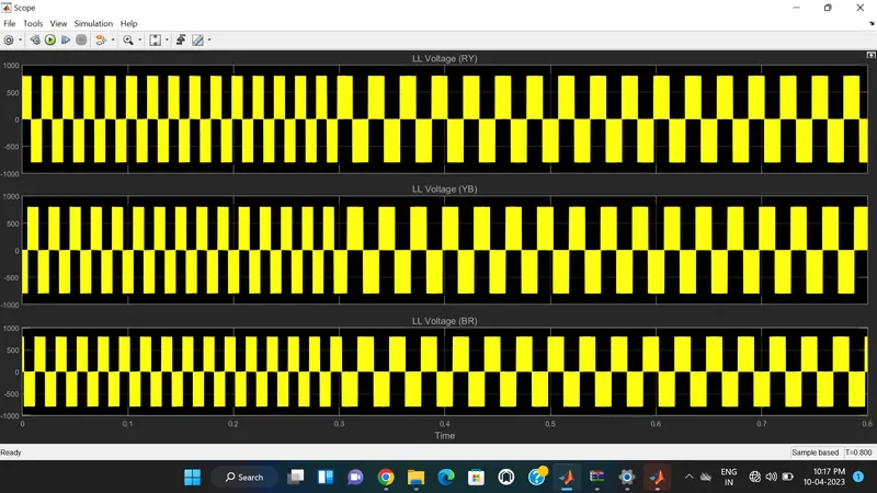
Stator line-to-line voltage is shown below -
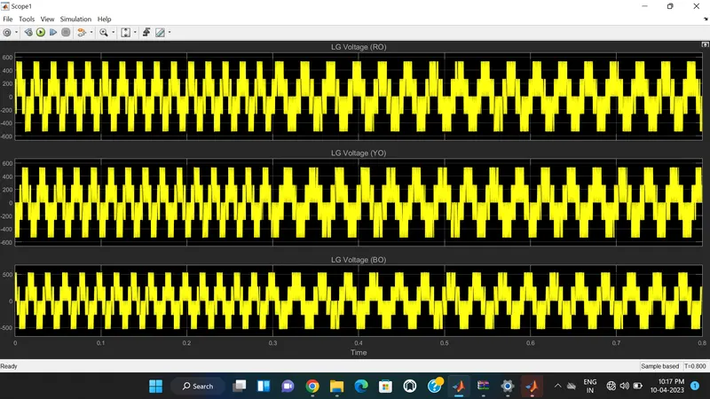
The stator line voltage is shown below -
The phase current, speed, and torque are shown below -
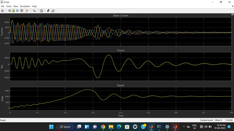
From the above plot, the phase current is at the top of the plot, the torque is in the middle, and the speed is at the bottom. At the time of starting of motor, high starting current is flow through it and therefore torque is also high and speed tries to matches to its initial speed values i.e 1500rpm as hown in above plot. This all happened for a very short duration of time. Then motor runs normally in running condition.
At 0.3 sec, frequency is changed from 50Hz to 33.33Hz by V/F control method the Torque of the motor is reduced and according to this speed is also reduced to 1000rpm. Then after some period of time motor control is achieved and speed gets maintained at 0.8 sec.
2. Use the 3 phase inductor motor theory to derive the transfer function of 3 phase Induction Motor
Solution -
Aim - To Use the 3-phase inductor motor theory to derive the transfer function of 3 phase Induction Motor.
The transfer function of an Induction motor is obtained from the Mathematical modeling of an induction motor and by taking all the required basic Equations.
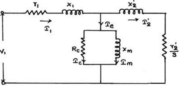
r1=resistance of Stator
X1=Stator leakage reactance
I1=stator current
Rc=shunt branch resistance
Xm=magnetizing reactance
Ie=per phase no-load current
I2=Rotor current
I2'=Rotor Current per phase referred to as stator
X2'=standstill rotor reactance referred to as stator
r2'=rotor resistance referred to as stator
V1=Stator Voltage
E1=stator induced emf
s=slip
The electrical equation of the machine is
Va=Ia*Ra+JXs*Ia+Eb
where Eb ∝ (dθ/dt)
Applying Laplace transforms,
Va (s) = Ia(s) (Ra + jXs) + Eb(s)
we know that
Eb = Kt sθ(s)
substituting, we get
Va(s)=Ia (s) Z(s) + Kt s θ(s)
Va (s)−Kt (s) sθ(s) / Z(s) = Ia(s)
Electrical Torque is given by
Te=E2sinθ
Mechanical Torque is given by
Tm=Jθ + Bθ
Taking Laplace Transforms,
Tm (s) = (Js2+Bs) θ(s)
Tm=Te⇒E2 θ(s) = Js2 + Bs(θ(s))
(Js2+Bs−E2) θ(s) = Tm
Js2+Bs−E2=(Tm / θ(s))
θ(s) / Tm (s) =1 / (Js2+ Bs−E2)
we know that T∝ϕIa cosθ (take θ=0)
T = Kϕ Ia
T = Kϕ (s) Ia(s)
From the above we know
Ka [Va(s)−Kts θ(s)] Z(s)=(Js2+Bs−E2) θ(s)
Ka Va (s) = (Js2+Bs−E2) θ(s) Z(s) + Kts θ(s)
[Va(s) / θ(s)] = (Js2+Bs−E2) Z(s) + Ka Kts Ka
θ(s) / Va(s) = Ka (Js2+Bs−E2) Z(s) + Ka Kts
θ(s) / Va(s) = Ka (Js2+Bs−E2) (Ra + Las) + Ka Kts
The transfer function of the induction motor is given as
θ(s) / Va(s) = Ka / [JLas3 + (Ra J + B La) s2 + (B Ra + Ka Kt) s]
3. Model 3 phase induction motor with a 3 phase inverter using Direct Torque control using an Average Model, Implement both torque and flux control to achieve desired power.
Design Parameters:
- Initial Speed = 0 RPM
- Flux Target = 2.5 webers
- DC Voltage = 500 V;
- Fundamental Frequency = 60 Hz
- Speed Step Time = 0.01 secs
- Determine fundamental speed based upon fundamental frequency
- Determine the switching sequence for direct torque control
- Moment of Inertia = 0.1 Kgm^2
- Load Torque Initial = 0 Nm
- Final Load Torque = 50 Nm
- Torque Step Time = 0.03 secs
Motor Parameters: (Create an Average Model)
- Stator Resistance = 0.5 Ohms
- Rotor Resistance = 0.2 Ohms
- Stator Leakage Inductance = 20 mH
- Rotor Leakage Inductance = 10 mH
- Magnetizing Inductance = 200 mH
- Number of Poles = 4
- Torque to Speed
Solution -
AIM -Model 3 phase induction motor with a 3-phase inverter using Direct Torque control using an Average Model, implement both torque and flux control to achieve the desired power.
Theory -
Direct Torque Controller -
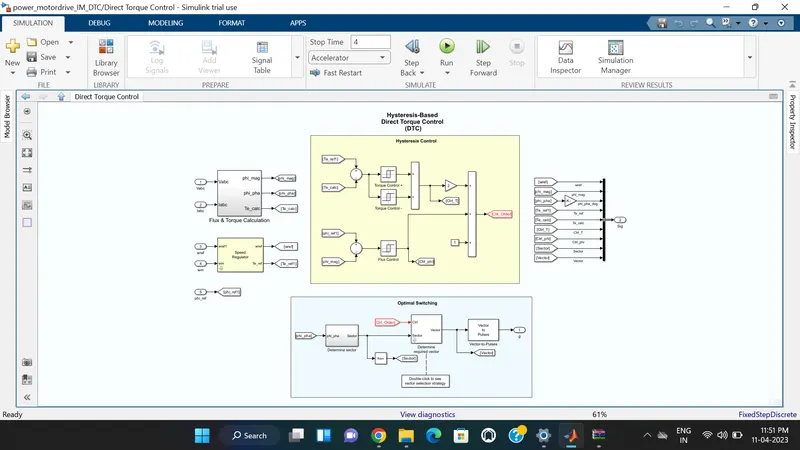
Direct torque control (DTC) is a technique that allows you to instantaneously control the motor magnetic flux and its electromagnetic torque in a decoupled way. Controlling the torque directly permits accurate static and dynamic speed regulation. The main components of the DTC subsystem are:
- Flux and Torque Calculation — The stator flux linkage is estimated by integrating the stator voltages, and torque is calculated based on the estimated flux and the motor currents.
- Speed Regulator — The regulator compares the actual motor speed with the speed reference and generates the torque reference.
- Hysteresis Control — The calculated flux magnitude and torque are compared with the reference values. When the resulting flux or torque error crosses either the positive or negative hysteresis band value, a control signal is activated in order to correct the error.
- Optimal Switching — Pulses to the motor inverter are produced based on the control signals generated by the hysteresis control and the stator flux linkage position.
The figure below illustrates the strategy used to determine the best voltage vector when the flux linkage is located in sector 0.
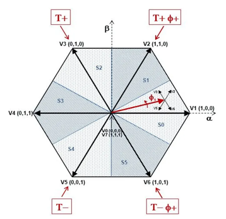
The image shows four cases:
- V3 is selected when the electromagnetic torque should be increased and the flux should stay unchanged. Selecting the V3 voltage vector speeds up the flux and thus applies an acceleration torque to the rotor while slightly decreasing the flux magnitude.
- V2 is selected when the electromagnetic torque should be increased and the flux should be increased. Selecting the V2 voltage vector slightly speeds up the flux and increases its magnitude.
- V6 is selected when the electromagnetic torque should be reduced and the flux should be increased. Selecting the V6 voltage vector slows down the flux and thus applies a deceleration torque to the rotor while increasing the flux magnitude.
- V5 is selected when the electromagnetic torque should be reduced and the flux should stay unchanged. Selecting V5 the voltage vector applies a deceleration torque to the rotor, slightly decreasing the flux magnitude. Note that voltage vectors V1 and V4 are not selected in sector 0. Using these two vectors would have too much negative impact on the desired flux value. Finally, to keep the torque and the flux unchanged, the null voltage vectors V0 or V7 are selected.
When the flux linkage vector moves to sector 1, the selected voltage vectors become V4 for case 1, V3 for case 2, V1 for case 3, and V6 for case 4, and vectors V2 and V5 are not used. This 60-degree shift in the voltage vectors happens each time the flux linkage vector enters a new sector.
SIMULINK MODEL -
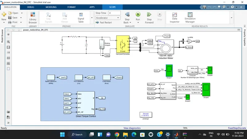
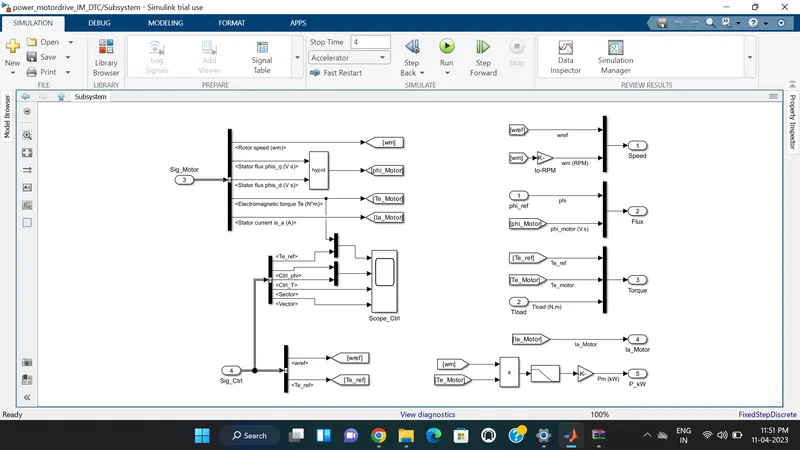
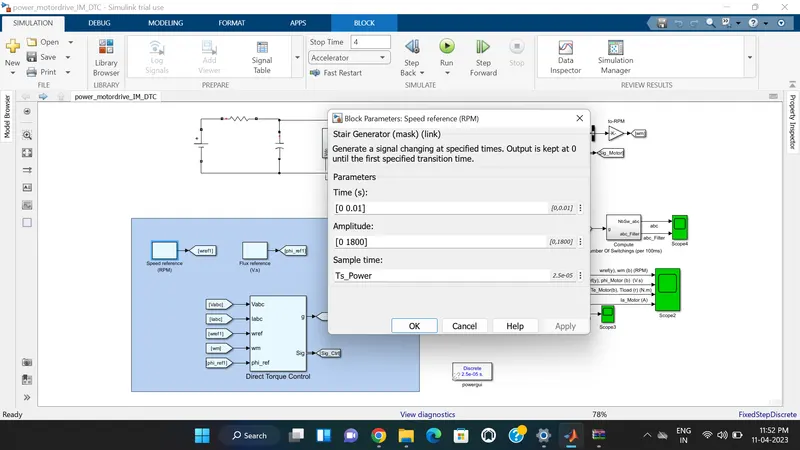
Each block’s properties are shown below -
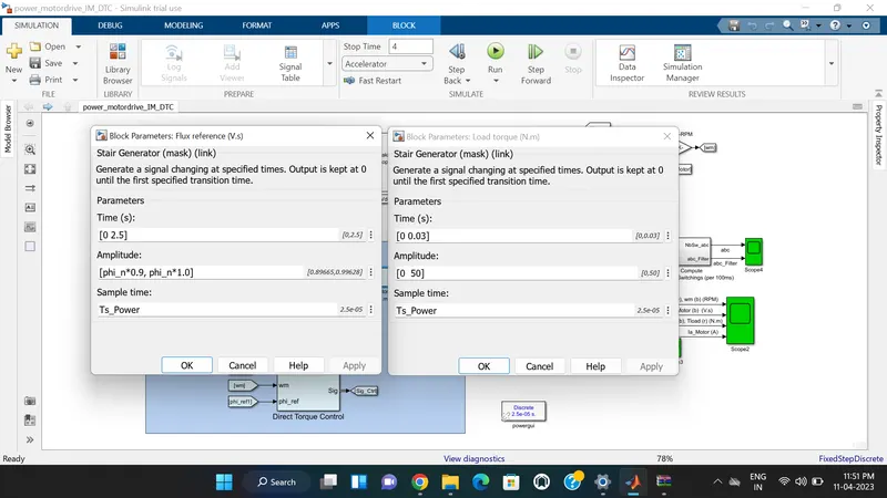
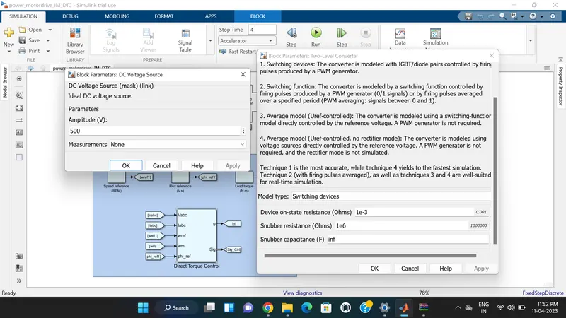
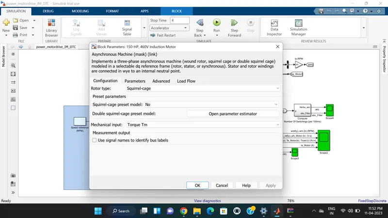
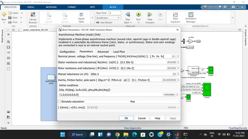
By using the referance torque, torque calculated, Phi referance and Phi magnitute we can generate the control order. this is the controlling of Flux.
By using Phi angle we can estimate the sector. by sector and control order we can generate the vector. From vector we can generate the Gate pulses.
Determining fundamental speed based upon fundamental frequency -
speed Ns = 120 * f / P
fundamental frequency (F) = 60Hz
number of poles P = 4
Fundamental speed Ns = 120 * 60 / 4
Fundamental speed N = 1800
EXPLANATION -
The DC voltage sourse of 500V is connected to a three-phase, two-level converter. This converter generates the variable voltage and frequency required for the variable-speed operation of the 150 HP induction motor. In addition, a braking chopper is connected to the DC bus in order to dissipate the kinetic energy of the motor during deceleration.
As DC voltage sourse is not connectected directly to DC link capacitor so a resistor of 1 ohm is connected in series between voltage sourse and Dc link capacitor as shown in above model.
An inverter-fed induction motor drive can be controlled through various techniques depending on the application, desired performance, and controller design complexity. Commonly used schemes are scalar control (V/Hz control or open loop flux control) or vector control (field-oriented control or direct torque control). This example uses a hysteresis-based direct torque control (DTC) technique.
Run the simulation and observe the waveforms on Scope2. Initially, the flux reference is set to 0.9 V.s.
At 0.01 s, the speed reference is set to 1800 RPM and the motor starts to accelerate. The motor speed precisely follows the speed reference, whose maximum rate of change is limited to 1200 rpm/s.
At 0.03 s, a load torque of 50 N.m is applied to the motor. The DTC control operates to maintain the motor speed at 1800 RPM.
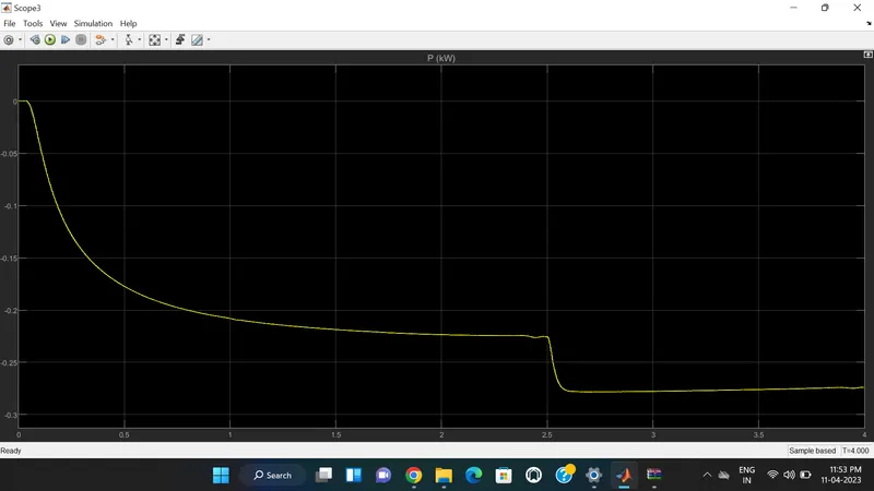
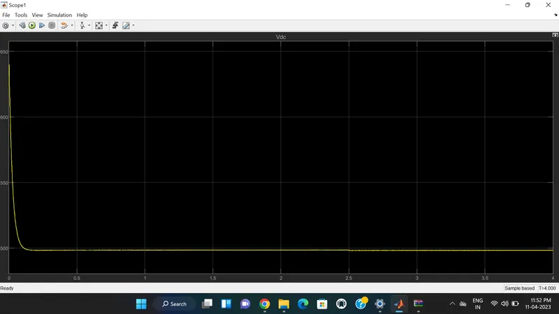
Observe on Scope 1 that the braking chopper operation dissipates the kinetic energy produced by the motor in order to avoid overvoltage on the DC bus. Finally, at 2.5 s, the flux reference is increased from 0.9 to 1.0 V.s.
RESULT -
The Induction motor speed, current, and power are measured and shown in the below plots.
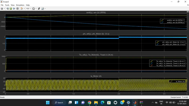
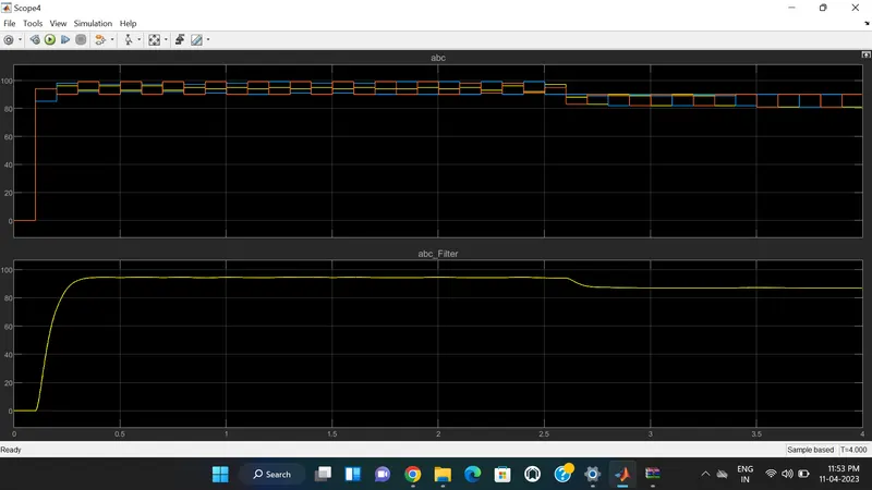
Below plot shows the filtered waveform obtained from Number of switching block.
Plot of Vdc is shown in below.
CONCLUSION -
The Three Phase Induction Motor Drive is modelled and its speed is controlled using both the V/F Control method and Direct Torque Control Method and the Transfer Function of the Induction Motor is determined.