Project 2 - Modeling of 3 phase Induction Motor Drive
2)
Induction motor:
An Induction motor or is an AC electric motor in which the electric current in the rotor needed to produce torque is obtained by electromagnetic induction from the magnetic field of the stator winding. An induction motor can therefore be made without electrical connections to the rotor. An induction motor's rotor can be either wound type or squirrel-cage type. They are self-starting, reliable and economical. Single-phase induction motors are used extensively for smaller loads, such as household appliances like fans. Although traditionally used in fixed-speed service, induction motors are increasingly being used with variable-frequency drives (VFD) in variable-speed service. VFDs offer especially important energy savings opportunities for existing and prospective induction motors in variable-torque centrifugal fan, pump and compressor load applications. Squirrel cage induction motors are very widely used in both fixed-speed and variable-frequency drive applications.
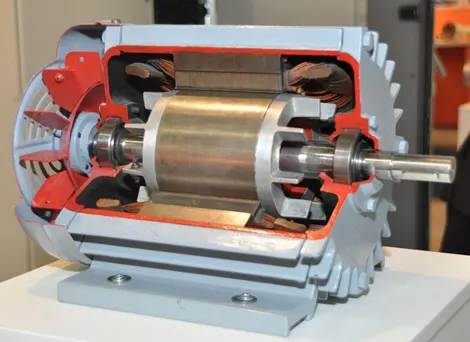
In both induction and synchronous motors, the AC power supplied to the motor's stator creates a magnetic field that rotates in synchronism with the AC oscillations. Whereas a synchronous motor's rotor turns at the same rate as the stator field, an induction motor's rotor rotates at a somewhat slower speed than the stator field. The induction motor stator's magnetic field is therefore changing or rotating relative to the rotor. This induces an opposing current in the induction motor's rotor, in effect the motor's secondary winding, when the latter is short-circuited or closed through an external impedance. The rotating magnetic flux induces currents in the windings of the rotor, in a manner similar to currents induced in a transformer's secondary winding(s).
The induced currents in the rotor windings in turn create magnetic fields in the rotor that react against the stator field. The direction of the magnetic field created will be such as to oppose the change in current through the rotor windings. The cause of induced current in the rotor windings is the rotating stator magnetic field, so to oppose the change in rotor-winding currents the rotor will start to rotate in the direction of the rotating stator magnetic field. The rotor accelerates until the magnitude of induced rotor current and torque balances the applied mechanical load on the rotation of the rotor. Since rotation at synchronous speed would result in no induced rotor current, an induction motor always operates slightly slower than synchronous speed.
Equivalent circuit of induction motor:
An induction motor is a well-known device which works on the principle of transformer. So, it is also called the rotating transformer. That is, when an EMF is supplied to its stator, then as a result of electromagnetic induction, a voltage is induced in its rotor. So, an induction motor is said to be a transformer with rotating secondary. Here, primary of transformer resembles stator winding of an induction motor and secondary resembles rotor.
The induction motor always runs below the synchronous or full load speed and the relative difference between the synchronous speed and speed of rotation is known as slip which is denoted by s.
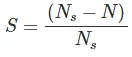
Where, Ns is synchronous speed of rotation which is given by
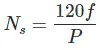
Where, f is the frequency of the supply voltage.
P is the number of poles of the machine.
The equivalent circuit of any machine shows the various parameter of the machine such as its Ohmic losses and also other losses.
The losses are modelled just by inductor and resistor. The copper losses are occurred in the windings so the winding resistance is taken into account. Also, the winding has inductance for which there is a voltage drop due to inductive reactance and also a term called power factor comes into the picture.
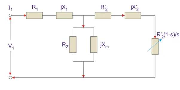
Here, R1 is the winding resistance of the stator.
X1 is the inductance of the stator winding.
Rc is the core loss component.
Xm is the magnetizing reactance of the winding.
R2/s is the power of the rotor, which includes output mechanical power and copper loss of rotor.
R2’ is the rotor winding resistance with referred to stator winding.
X2’ is the rotor winding inductance with referred to stator winding.
R2(1 – s) / s is the resistance which shows the power which is converted to mechanical power output or useful power. The power dissipated in that resistor is the useful power output or shaft power.
- Input power to stator- 3 V1I1Cos(Ɵ).
- Where, V1 is the stator voltage applied
- It is the current drawn by the stator winding.
- COS(0) is the stator power stator.
- Rotor input = Power input- Stator copper and iron losses.
- Rotor Copper loss = Slip × power input to the rotor.
- Rotor Copper loss = Slip × power input to the rotor.
Torque Equation:
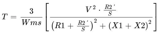
Where,
T – Torque (Nm)
Wms – (rad/s)
V – Per phase voltage
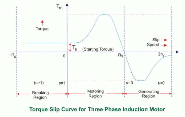
S = 0 to 1, S = 0 Motor is running at synchronous Speed
S = 1 Motor is stand still.