Project 2
1)
solution:
Given data:
Input voltage = 45-60V
Output voltage = 3V
Output current = 100A
Efficiency >85%
Assumptions:
Switching frequency = 20000H
Duty ratio =0.5
Calculations:
For this design we are using the forward converter formulas:
1) Duty cycle:
Vout/Vi = D.(N2/N1)
Let's assume that we will design for 50% Duty ratio:
N2/N1=0.1
These we choose the following:
N1=500
2)Since we choose D=0.5 then using equation we found that,
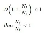
Thus we will choose,
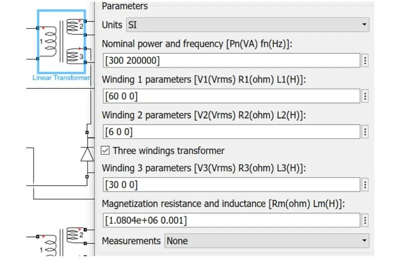
N3 =150turns
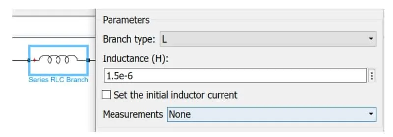
3) Now, we will choose an inductor for 40% current ripple:
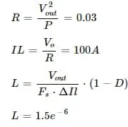
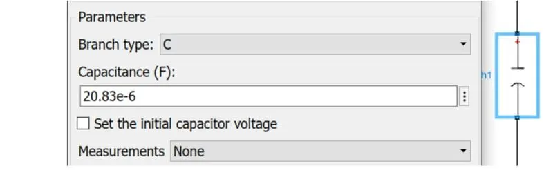
4) Now we are calculate the capacitor:
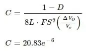
From all the above all calculations we are models now the interleacving DC/DC converter:
The recent development of battery powered application is improving the need of efficient step up dc-dc converter. Now a days step up conversion is widely used in many applications like electrical vehicles photovoltaic systems, uniteruptible power supplies and fuel cell system. By parallelling the converter the input current can be shared among inductor so that reliability and eficieny in power electronic .
System can be obtained in this paper the conventonal boost dc/dc converter and interleaved boost dc-dc converter are simulated using matlab/simulink and MULTISIM software. the converter are tested by varring the input voltage with a constant dutycycle in continuous conduction mode.
As for high efficiency we used multiphase system to increase the efficiency
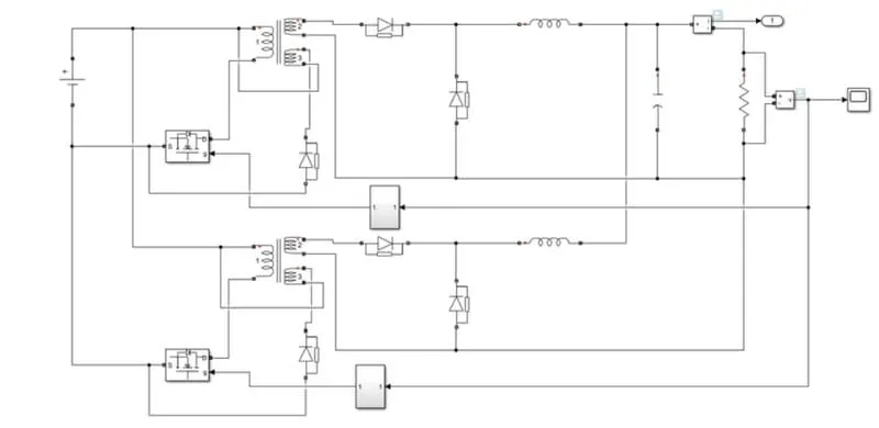
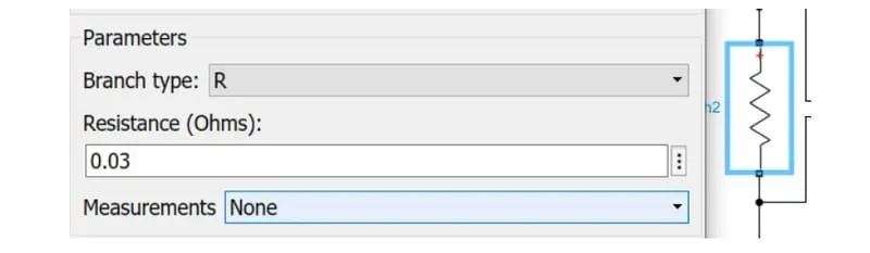
In this model we are using the following parameters which we calculated
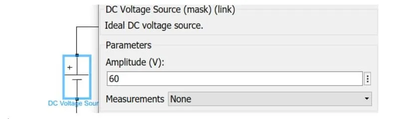
1) Input voltage:
2) Transformer capacity:
3) Inductor value:
4) Capacitor:
5) Output load:
6) Gate pulse:
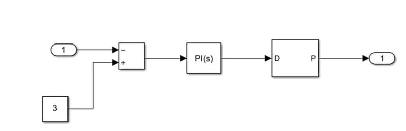
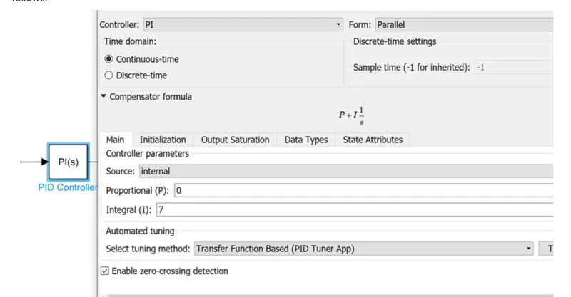
As we required the 3V so we were given the reference as the constant 3 and PID get the turned so PID values are as follows:
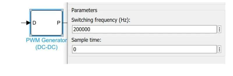
The frequency is choosen is 20000hz:
Now we run the model for 0.5 sec and get all outputs:
Output voltage:
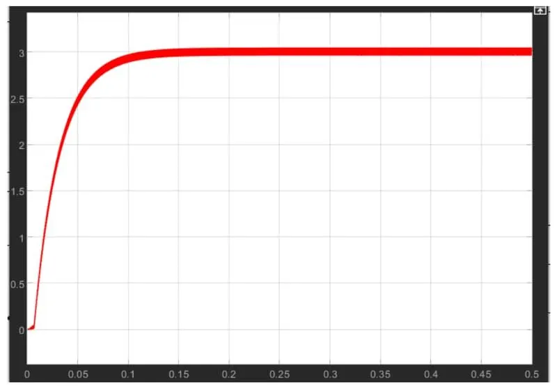
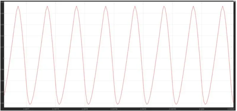
As we output voltage is getting 3 Volt same as we required with some ripples and ripple also same as we calculated which is shown in the following graph.
The ripple of output voltage:
Output current:
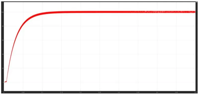
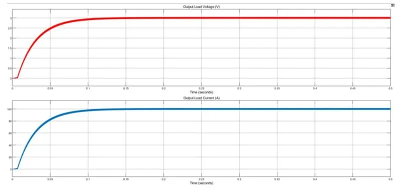
Current is 100A this is beacause of the isolated system and multiphase system getting the perfect as same as requirments:
Outputs voltage and current:
Input voltage:
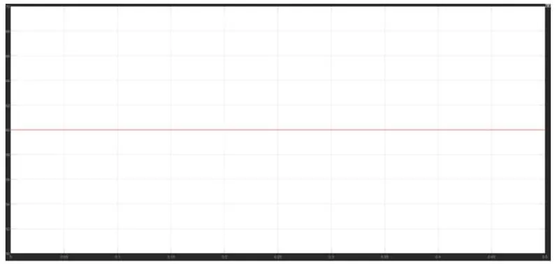
As our input voltage is 60V given the converter.
Input current:
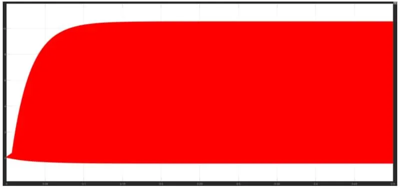
Beacause of switching action of MOSFET input current is looking like this if zoom it, it will look like step voltage which is shown in the following graph.
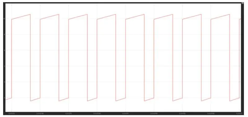
The current amplitude is max is 10 volt and the minimum voltage is near to zero so as calculate the average the values then were getting 4.7A approximately.
Inductor voltage:
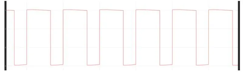
Voltage is as pus and magnitude are 2V and -4V.
1. The main aim is to get the efficiency as higher as possible and as see in our requirement are getting approximately same.
so we can say that our efficiency is above/more than 90%.
1. As efficiency is calculated from output power/input power so as we calculated for this converter as following:
Input voltage=60V
Input current =5A
Output voltage= 3V
Output current =100A
From all the above data we get the input power is 300W and output power is also 300W
so our efficiency as 100% without considering the ripple in voltage and current if we consider the ripple in voltage and current if we consider the ripple also we can get the effciency more than 90%.
Conclusion:
Those we designed the DC/DC converter the given data and get the required output with more than 90% effieciency.