Project 1 - Loss calculation for a DC/DC converter-MATLAB
1)
Ans:
Power electronics:
Power electronics is the application of electronic to the control and conversion of electric power.
The first high-power electronic devices were made using mercury-arc values. In modern systems, the conversion is performed with semiconductor switching devices such as diodes, thyristor, and power transistor such as the power MOSFET and IGBT.In contrast to electronic systems concerned with the transmission and processing of signals and data, substantial amounts of electrical energy are processed in power electronics. An AC/DC converter (rectifier) is the most typical power electronics device found in many consumer electronic devices, e.g. television sets, personal computor, battery charger, etc. The power range is typically from tens of watts to several hundred watts. In industry, a common application is the variable speed drive (VSD) that is used to control an induction motor. The power range of VSDs starts from a few hundred watts and ends at tens of megawatts.
The power conversion systems can be classified according to the type of the input and output power:
- AC to DC (rectifier)
- DC to AC (inverter)
- DC to DC (DC to DC converter)
- AC to AC (AC to AC converter)
Power MOSFET:
A breakthrough in power electronics came with the invention of the MOSFET(metal-oxide-semiconductor field-effect transistor) Generations of MOSFET transistors enabled power designers to achieve performance and density levels not possible with bipolar transistors. Due to improvements in MOSFET technology (initially used to produce intergrated circuit) the power MOSFET.In introduced the first vertical power MOSFET, which would later be known as the VMOS(V-groovMOSFET) frequencies than a bipolar transistor, but is limited to low voltage applications.
The power MOSFET is the most common power device in the world, due to its low gate drive power, fast switching speed,easy advanced paralleling capability,wide bandwidth, ruggedness, easy drive, simple biasing, ease of application, and ease of repair.It has a wide range of power electronic applications, such as portable information application power integrated circuits, cell phones,notebook computers, and the communication infrastructure that enables the internet.
In insulated-gate bipolartransistor (IGBT) was introduced. It became widely available in the 1990s. This component has the power handling capability of the bipolar transistor and the advantages of the isolated gate drive of the power MOSFET.
DC/AC Converter(inverter):
DC to AC converters produce an AC output waveform from a DC source. Applications include adjustable speed drives (ASD), uninterruptible power supplies(UPS), flexible AC transimission systems(FACTS), voltage compensators, and photovoltaic inverter. Topologies for these converters can be separated into two distinct categories: voltage source inverters and current source inverters. Voltage source inverters (VSIs) are named so because the independently controlled output is a voltage waveform. Similarly, current source inverters (CSIs) are distinct in that the controlled AC output is a current waveform.
DC to AC power conversion is the result of power switching devices, which are commonly fully controllable semiconductor power switches. The output waveforms are therefore made up of discrete values, producing fast transitions rather than smooth ones. For some applications, even a rough approximation of the sinusoidal waveform of AC power is adequate. Where a near sinusoidal waveform is required, the switching devices are operated much faster than the desired output frequency, and the time they spend in either state is controlled so the averaged output is nearly sinusoidal. Common modulation techniques include the carrier-based technique, or pulse-width modulation, space-vector technique, and the selective-harmonic technique.
Voltage source inverters have practical uses in both single-phase and three-phase applications. Single-phase VSIs utilize half-bridge and full-bridge configurations, and are widely used for power supplies, single-phase UPSs, and elaborate high-power topologies when used in multicell configurations. Three-phase VSIs are used in applications that require sinusoidal voltage waveforms, such as ASDs, UPSs, and some types of FACTS devices such as the statcom. They are also used in applications where arbitrary voltages are required, as in the case of active power filters and voltage compensators.
Current source inverters are used to produce an AC output current from a DC current supply. This type of inverter is practical for three-phase applications in which high-quality voltage waveforms are required.
A relatively new class of inverters, called multilevel inverters, has gained widespread interest. The normal operation of CSIs and VSIs can be classified as two-level inverters, due to the fact that power switches connect to either the positive or to the negative DC bus. If more than two voltage levels were available to the inverter output terminals, the AC output could better approximate a sine wave. It is for this reason that multilevel inverters, although more complex and costly, offer higher performance.
Each inverter type differs in the DC links used, and in whether or not they require freewheeling diodes. Either can be made to operate in square-wave or pulse-width modulation (PWM) mode, depending on its intended usage. Square-wave mode offers simplicity, while PWM can be implemented in several different ways and produces higher quality waveforms.
Voltage Source Inverters (VSI) feed the output inverter section from an approximately constant-voltage source.
The desired quality of the current output waveform determines which modulation technique needs to be selected for a given application. The output of a VSI is composed of discrete values. In order to obtain a smooth current waveform, the loads need to be inductive at the select harmonic frequencies. Without some sort of inductive filtering between the source and load, a capacitive load will cause the load to receive a choppy current waveform, with large and frequent current spikes.
- Single-phase half-bridge inverter
- Single-phase full-bridge inverter
- Three-phase voltage source inverter
1. Single-phase half-bridge inverter:
The single-phase voltage source half-bridge inverters are meant for lower voltage applications and are commonly used in power supplies. Figure shows the circuit schematic of this inverter.
Low-order current harmonics get injected back to the source voltage by the operation of the inverter. This means that two large capacitors are needed for filtering purposes in this design.As Figure illustrates, only one switch can be on at a time in each leg of the inverter. If both switches in a leg were on at the same time, the DC source would be shorted out.
Inverters can use several modulation techniques to control their switching schemes. The carrier-based PWM technique compares the AC output waveform, vc, to a carrier voltage signal, vΔ. When vc is greater than vΔ, S+ is on, and when vc is less than vΔ, S- is on. When the AC output is at frequency fc with its amplitude at vc, and the triangular carrier signal is at frequency fΔ with its amplitude at vΔ, the PWM becomes a special sinusoidal case of the carrier based PWM. This case is dubbed sinusoidal pulse-width modulation (SPWM).For this, the modulation index, or amplitude-modulation ratio, is defined as ma = vc/v∆ .
The normalized carrier frequency, or frequency-modulation ratio, is calculated using the equation mf = f∆/fc .
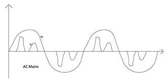
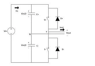
if the over-modulation region, ma, exceeds one, a higher fundamental AC output voltage will be observed, but at the cost of saturation. For SPWM, the harmonics of the output waveform are at well-defined frequencies and amplitudes. This simplifies the design of the filtering components needed for the low-order current harmonic injection from the operation of the inverter. The maximum output amplitude in this mode of operation is half of the source voltage. If the maximum output amplitude, ma, exceeds 3.24, the output waveform of the inverter becomes a square wave.
As was true for Pulse-Width Modulation (PWM), both switches in a leg for square wave modulation cannot be turned on at the same time, as this would cause a short across the voltage source. The switching scheme requires that both S+ and S- be on for a half cycle of the AC output period. The fundamental AC output amplitude is equal to vo1 = vaN = 2vi/π .
Its harmonics have an amplitude of voh = vo1/h.
Therefore, the AC output voltage is not controlled by the inverter, but rather by the magnitude of the DC input voltage of the inverter.
Using selective harmonic elimination (SHE) as a modulation technique allows the switching of the inverter to selectively eliminate intrinsic harmonics. The fundamental component of the AC output voltage can also be adjusted within a desirable range. Since the AC output voltage obtained from this modulation technique has odd half and odd quarter-wave symmetry, even harmonics do not exist. Any undesirable odd (N-1) intrinsic harmonics from the output waveform can be eliminated.
2. Single-phase full-bridge inverter:
The full-bridge inverter is similar to the half bridge-inverter, but it has an additional leg to connect the neutral point to the load.Figure shows the circuit schematic of the single-phase voltage source full-bridge inverter.
To avoid shorting out the voltage source, S1+, and S1- cannot be on at the same time, and S2+ and S2- also cannot be on at the same time. Any modulating technique used for the full-bridge configuration should have either the top or the bottom switch of each leg on at any given time. Due to the extra leg, the maximum amplitude of the output waveform is Vi, and is twice as large as the maximum achievable output amplitude for the half-bridge configuration.
States 1 and 2 from Table 2 are used to generate the AC output voltage with bipolar SPWM. The AC output voltage can take on only two values, either Vi or –Vi. To generate these same states using a half-bridge configuration, a carrier based technique can be used. S+ being on for the half-bridge corresponds to S1+ and S2- being on for the full-bridge. Similarly, S- being on for the half-bridge corresponds to S1- and S2+ being on for the full bridge. The output voltage for this modulation technique is more or less sinusoidal, with a fundamental component that has an amplitude in the linear region of less than or equal to one vo1 =vab1= vi • ma
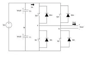
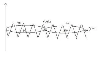
Unlike the bipolar PWM technique, the unipolar approach uses states 1, 2, 3, and 4 from Table 2 to generate its AC output voltage. Therefore, the AC output voltage can take on the values Vi, 0 or –V [1]i. To generate these states, two sinusoidal modulating signals, Vc and –Vc, are needed, as seen in Figure .
Vc is used to generate VaN, while –Vc is used to generate VbN. The following relationship is called unipolar carrier-based SPWM vo1 =2 • vaN1= vi • ma.
The phase voltages VaN and VbN are identical, but 180 degrees out of phase with each other. The output voltage is equal to the difference of the two-phase voltages, and do not contain any even harmonics. Therefore, if mf is taken, even the AC output voltage harmonics will appear at normalized odd frequencies, fh. These frequencies are centered on double the value of the normalized carrier frequency. This particular feature allows for smaller filtering components when trying to obtain a higher quality output waveform.
As was the case for the half-bridge SHE, the AC output voltage contains no even harmonics due to its odd half and odd quarter-wave symmetry.
3.Three-phase voltage source inverter:
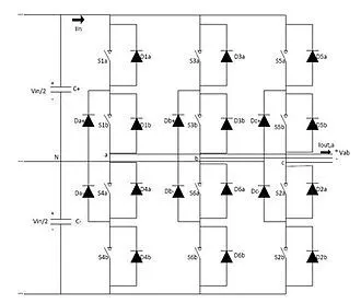
Single-phase VSIs are used primarily for low power range applications, while three-phase VSIs cover both medium and high power range applications.Figure shows the circuit schematic for a three-phase VSI.
Switches in any of the three legs of the inverter cannot be switched off simultaneously due to this resulting in the voltages being dependent on the respective line current's polarity. States 7 and 8 produce zero AC line voltages, which result in AC line currents freewheeling through either the upper or the lower components. However, the line voltages for states 1 through 6 produce an AC line voltage consisting of the discrete values of Vi, 0 or –Vi.
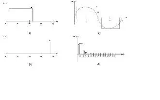
For three-phase SPWM, three modulating signals that are 120 degrees out of phase with one another are used in order to produce out-of-phase load voltages. In order to preserve the PWM features with a single carrier signal, the normalized carrier frequency, mf, needs to be a multiple of three. This keeps the magnitude of the phase voltages identical, but out of phase with each other by 120 degrees. The maximum achievable phase voltage amplitude in the linear region, ma less than or equal to one, is vphase = vi / 2. The maximum achievable line voltage amplitude is Vab1 = vab • √3 / 2
The only way to control the load voltage is by changing the input DC voltage.
AC to AC converter:
Converting AC power to AC power allows control of the voltage, frequency, and phase of the waveform applied to a load from a supplied AC system . The two main categories that can be used to separate the types of converters are whether the frequency of the waveform is changed. that don't allow AC to AC converter the user to modify the frequencies are known as AC Voltage Controllers, or AC Regulators. AC converters that allow the user to change the frequency are simply referred to as frequency converters for AC to AC conversion. Under frequency converters there are three different types of converters that are typically used: cycloconverter, matrix converter, DC link converter (aka AC/DC/AC converter).
AC voltage controller:The purpose of an AC Voltage Controller, or AC Regulator, is to vary the RMS voltage across the load while at a constant frequency.Three control methods that are generally accepted are ON/OFF Control, Phase-Angle Control, and Pulse-Width Modulation AC Chopper Control (PWM AC Chopper Control). All three of these methods can be implemented not only in single-phase circuits, but three-phase circuits as well.
- ON/OFF Control: Typically used for heating loads or speed control of motors, this control method involves turning the switch on for n integral cycles and turning the switch off for m integral cycles. Because turning the switches on and off causes undesirable harmonics to be created, the switches are turned on and off during zero-voltage and zero-current conditions (zero-crossing), effectively reducing the distortion.
- Phase-Angle Control: Various circuits exist to implement a phase-angle control on different waveforms, such as half-wave or full-wave voltage control. The power electronic components that are typically used are diodes, SCRs, and Triacs. With the use of these components, the user can delay the firing angle in a wave, which will only cause part of the wave to be in output.
- PWM AC Chopper Control: The other two control methods often have poor harmonics, output current quality, and input power factor. In order to improve these values PWM can be used instead of the other methods. What PWM AC Chopper does is have switches that turn on and off several times within alternate half-cycles of input voltage.
Matrix converter and cycloconverter: cycloconverter are widely used in industry for ac to ac conversion, because they are able to be used in high-power applications. They are commutated direct frequency converters that are synchronised by a supply line. The cycloconverters output voltage waveforms have complex harmonics with the higher-order harmonics being filtered by the machine inductance. Causing the machine current to have fewer harmonics, while the remaining harmonics causes losses and torque pulsations. Note that in a cycloconverter, unlike other converters, there are no inductors or capacitors, i.e. no storage devices. For this reason, the instantaneous input power and the output power are equal.
- Single-Phase to Single-Phase cycloconverter: Single-Phase to Single-Phase Cycloconverters started drawing more interest recently because of the decrease in both size and price of the power electronics switches. The single-phase high frequency ac voltage can be either sinusoidal or trapezoidal. These might be zero voltage intervals for control purpose or zero voltage commutation.
- Three-Phase to Single-Phase cycloconverter: There are two kinds of three-phase to single-phase cycloconverters: 3φ to 1φ half wave cycloconverters and 3φ to 1φ bridge cycloconverters. Both positive and negative converters can generate voltage at either polarity, resulting in the positive converter only supplying positive current, and the negative converter only supplying negative current.
With recent device advances, newer forms of cycloconverters are being developed, such as matrix converters. The first change that is first noticed is that matrix converters utilize bi-directional, bipolar switches. A single phase to a single phase matrix converter consists of a matrix of 9 switches connecting the three input phases to the tree output phase. Any input phase and output phase can be connected together at any time without connecting any two switches from the same phase at the same time; otherwise this will cause a short circuit of the input phases. Matrix converters are lighter, more compact and versatile than other converter solutions. As a result, they are able to achieve higher levels of integration, higher temperature operation, broad output frequency and natural bi-directional power flow suitable to regenerate energy back to the utility.
The matrix converters are subdivided into two types: direct and indirect converters. A direct matrix converter with three-phase input and three-phase output, the switches in a matrix converter must be bi-directional, that is, they must be able to block voltages of either polarity and to conduct current in either direction. This switching strategy permits the highest possible output voltage and reduces the reactive line-side current. Therefore, the power flow through the converter is reversible. Because of its commutation problem and complex control keep it from being broadly utilized in industry.
Unlike the direct matrix converters, the indirect matrix converters has the same functionality, but uses separate input and output sections that are connected through a dc link without storage elements. The design includes a four-quadrant current source rectifier and a voltage source inverter. The input section consists of bi-directional bipolar switches. The commutation strategy can be applied by changing the switching state of the input section while the output section is in a freewheeling mode. This commutation algorithm is significantly less complex, and has higher reliability as compared to a conventional direct matrix converter.
DC lonk converter:DC Link Converters, also referred to as AC/DC/AC converters, convert an AC input to an AC output with the use of a DC link in the middle. Meaning that the power in the converter is converted to DC from AC with the use of a rectifier, and then it is converted back to AC from DC with the use of an inverter. The end result is an output with a lower voltage and variable (higher or lower) frequency.Due to their wide area of application, the AC/DC/AC converters are the most common contemporary solution. Other advantages to AC/DC/AC converters is that they are stable in overload and no-load conditions, as well as they can be disengaged from a load without damage.
Hybrid matrix converter:Hybrid matrix converters are relatively new for AC/AC converters. These converters combine the AC/DC/AC design with the matrix converter design. Multiple types of hybrid converters have been developed in this new category, an example being a converter that uses uni-directional switches and two converter stages without the dc-link; without the capacitors or inductors needed for a dc-link, the weight and size of the converter is reduced. Two sub-categories exist from the hybrid converters, named hybrid direct matrix converter (HDMC) and hybrid indirect matrix converter (HIMC). HDMC convert the voltage and current in one stage, while the HIMC utilizes separate stages, like the AC/DC/AC converter, but without the use of an intermediate storage element.
Application: Below is a list of common applications that each converter is used in.
- AC voltage controller: Lighting control; domestic and industrial heating; speed control of fan, pump or hoist drives, soft starting of induction motors, static AC switches (temperature control, transformer tap changing, etc.)
- Cycloconverter: High-power low-speed reversible AC motor drives; constant frequency power supply with variable input frequency; controllable VAR generators for power factor correction; AC system interties linking two independent power systems.
- Matrix converter: Currently the application of matrix converters are limited due to the non-availability of bilateral monolithic switches capable of operating at high frequency, complex control law implementation, commutation, and other reasons. With these developments, matrix converters could replace cycloconverters in many areas.
- DC link: Can be used for individual or multiple load applications of machine building and construction