Project 2 - Modeling of 3 phase Induction Motor Drive
EVREFRESHER BATCH 5
ANSWER:
PARAMETERS :
- Power = 100 HP
- DC Voltage = 800 V
- Output Voltage = 460 VRMS – line to line
- Initial Speed = 1500 RPM
- Final Speed = 1000 RPM
- Initial Load Torque = 10 Nm
- Final Torque=20 Nm
- Torque Step Time = 0.1 secs
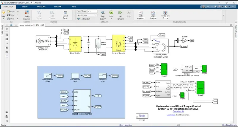
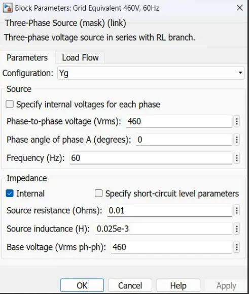
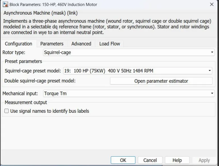
The electrical energy is supplied by a three-phase AC/DC diode rectifier connected to a 460 V, 60 Hz grid equivalent. The DC bus is connected to a three-phase, two-level converter. This converter generates the variable voltage and frequency required for variable-speed operation of the 150 HP induction motor. In addition, a braking chopper is connected to the DC bus in order to dissipate the kinetic energy of the motor during deceleration.
An inverter-fed induction motor drive can be controlled through various techniques depending on application, desired performance, and controller design complexity. Commonly used schemes are scalar control (V/Hz control or open loop flux control) or vector control (field-oriented control or direct torque control). This example uses a hysteresis-based direct torque control (DTC) technique.
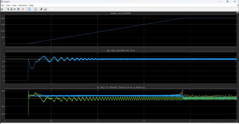
simulation results :
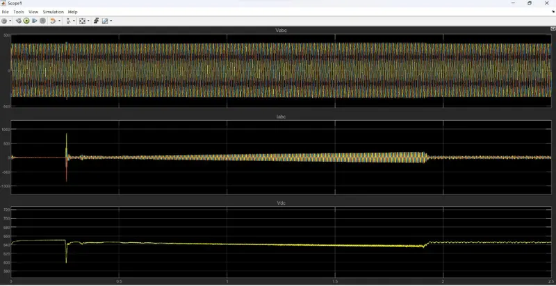
input vottage and vdc:
switching :
the flux reference is set to 0.9 V.s.
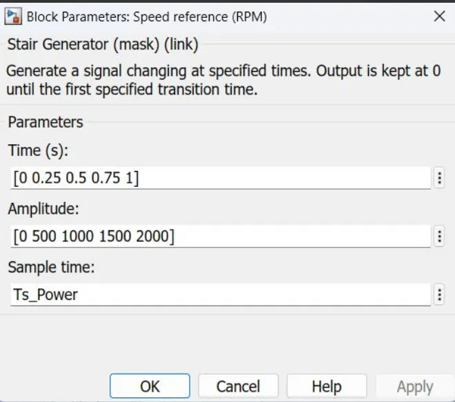
At 0.1 s, the speed reference is set to 1500 RPM and the motor starts to accelerate. The motor speed precisely follows the speed reference, whose maximum rate of change is limited to 1200 rpm/s. The 1500 RPM set point is reached at 1.35 s.
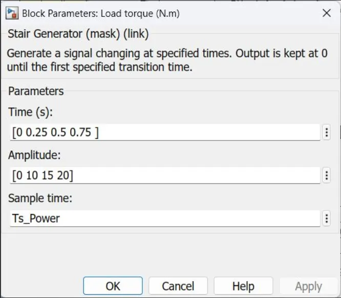
At 1.5 s, a load torque of 500 N.m is applied to the motor. The DTC control operates to maintain the motor speed at 1500 RPM.
At 2 s, the load torque is reduced to 50 N.m and at 2.5 s, the speed reference is reduced to 500 RPM. Observe on Scope 1 that the braking chopper operation dissipates the kinetic energy produced by the motor in order to avoid overvoltage on the DC bus. Finally, at 3.5 s, the flux reference is increased from 0.9 to 1.0 V.s.