Project 2 - Modeling of 3 phase Induction Motor Drive
EV Refresher batch5
PROJECT-2
Design parameters
- Power = 100 HP
- DC Voltage = 800 V
- Output Voltage = 460 VRMS – line to line
- Initial Speed = 1500 RPM
- Final Speed = 1000 RPM
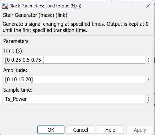
- Initial Load Torque = 10 Nm
- Final Torque=20 Nm
- Torque Step Time = 0.1 secs
Operation of Induction motor:
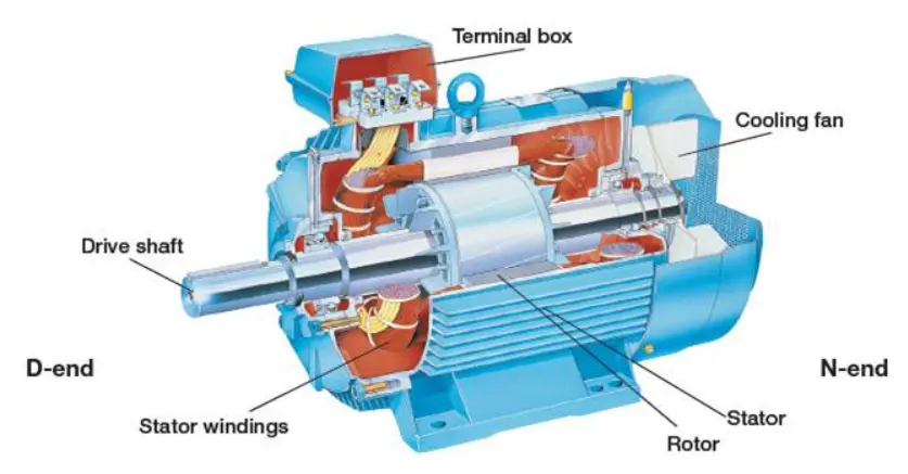
In induction motor, the AC power supplied to the motor's stator creates a magnetic field that rotates in synchronism with the AC oscillations. Whereas a synchronous motor's rotor turns at the same rate as the stator field, an induction motor's rotor rotates at a somewhat slower speed than the stator field. The induction motor stator's magnetic field is therefore changing or rotating relative to the rotor. This induces an opposing current in the induction motor's rotor, in effect the motor's secondary winding, when the latter is short-circuited or closed through an external impedance.[The rotating magnetic flux induces currents in the windings of the rotor.
The induced currents in the rotor windings in turn create magnetic fields in the rotor that react against the stator field. The direction of the magnetic field created will be such as to oppose the change in current through the rotor windings.
The cause of induced current in the rotor windings is the rotating stator magnetic field, so to oppose the change in rotor-winding currents the rotor will start to rotate in the direction of the rotating stator magnetic field. The rotor accelerates until the magnitude of induced rotor current and torque balances the applied mechanical load on the rotation of the rotor. Since rotation at synchronous speed would result in no induced rotor current, an induction motor always operates slightly slower than synchronous speed.
MODEL
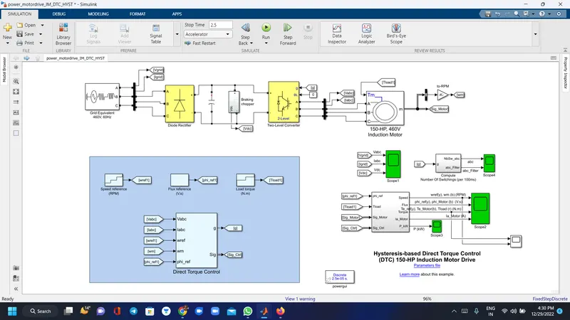
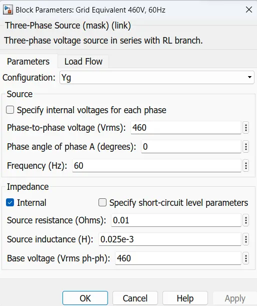
The electrical energy is supplied by a three-phase AC/DC diode rectifier connected to a 460 V, 60 Hz grid equivalent. The DC bus is connected to a three-phase, two-level converter. This converter generates the variable voltage and frequency required for variable-speed operation of the 150 HP induction motor. In addition, a braking chopper is connected to the DC bus in order to dissipate the kinetic energy of the motor during deceleration.
An inverter-fed induction motor drive can be controlled through various techniques depending on application, desired performance, and controller design complexity. Commonly used schemes are scalar control (V/Hz control or open loop flux control) or vector control (field-oriented control or direct torque control). This example uses a hysteresis-based direct torque control (DTC) technique.
parameters
torque
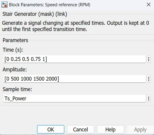
Reference speed
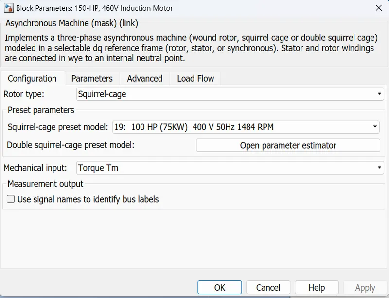
motor
grid
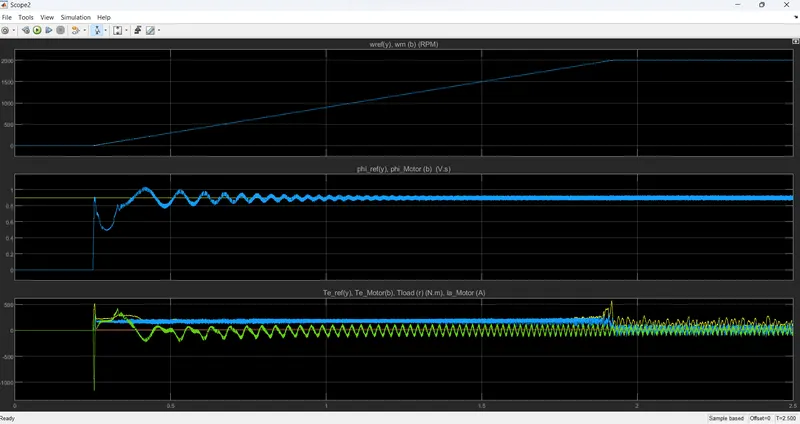
simulation results
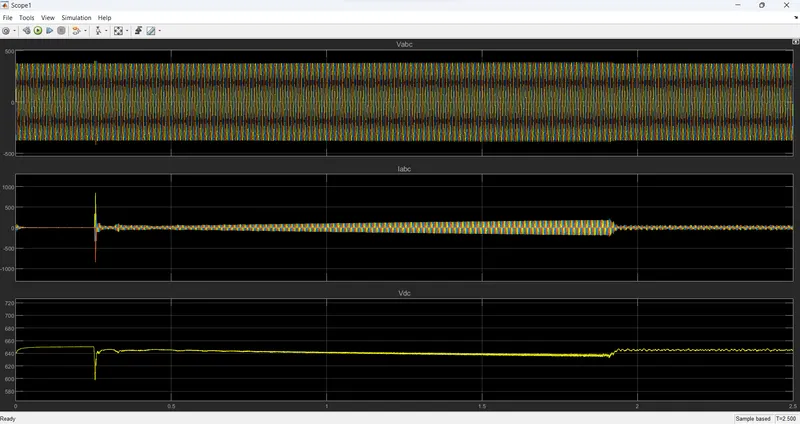
input ac voltage and current ,DC voltage
switching
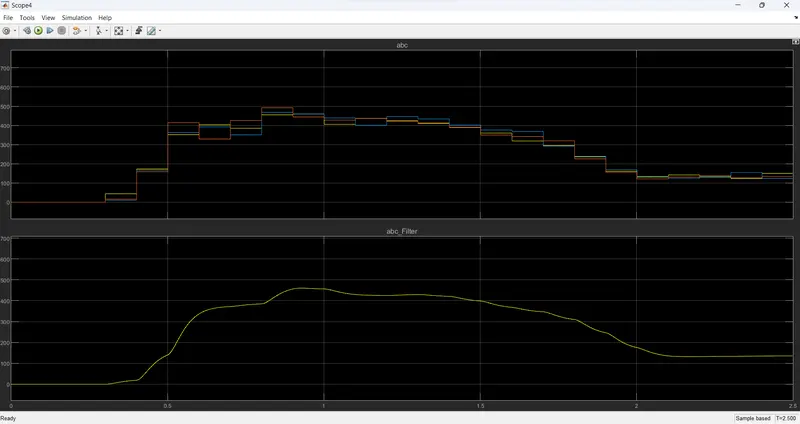
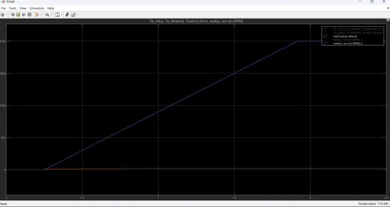
torque and reference speed