Project - 2 - Meshing on the suspension Assembly
AIM; To perform the clean-up of geometrical errors in the given Suspension Assembly model and mesh them with mentioned Quality criteria.
OBJECTIVE;
- For the given assembly, check for the geometrical errors and mesh with the given element Quality criteria.
- Use tetra elements to model non-uniform thickness components.
- After meshing the component, the thickness has to be assigned for mid surfaces.
- Finaly use Appropriate connections to connect the components.
PROCEDURE;
- Import the given suspension model.
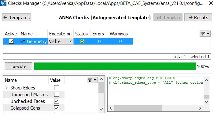
- Perform geometry clean up and avoid all the geometry errors.
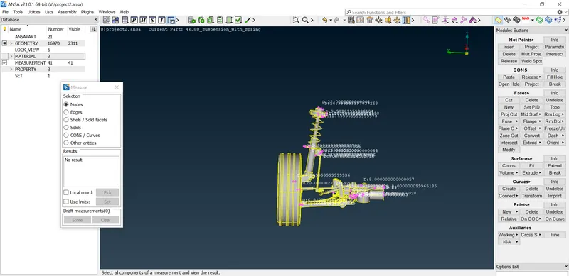
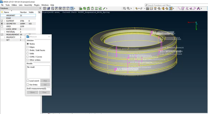
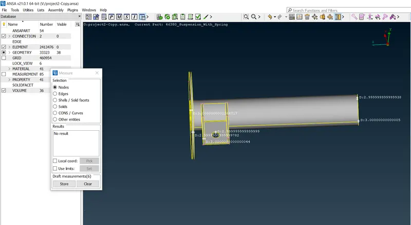
- Measure the thickness in various locations of the part for identifying the geometry component.
- Take mid surfaces only when the thickness is uniform and less than 5 mm (Element type: Mixed elements).
- Use tetra elements to model non-uniform thickness components (Element type: Tra elements).
- Assign Property ID for the midsurface and set the Quality criteria for meshing.
- Perform the Shell mesh for the the mid-surfaces.
- Define volume and solid mesh for the non uniform thickness elements.
- Avoid all the tetra collapse & other quality issues.
- Give the appropriate connections to the components.
GIVEN MODEL;
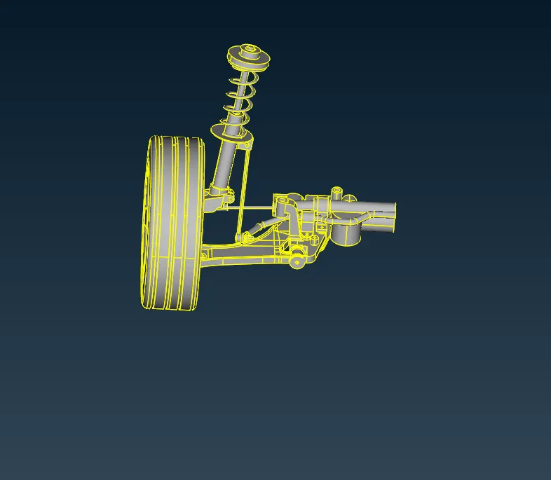
Perform geometry clean up and avoid all the geometry errors.
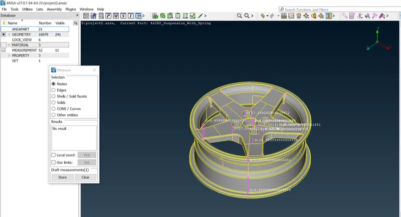
Measure the thickness in various locations of the part for identifying the geometry component.
For measuring, go the utilites Tab ?> click on measurnment> select the nodes options and identfiy the thickness in between the nodes.
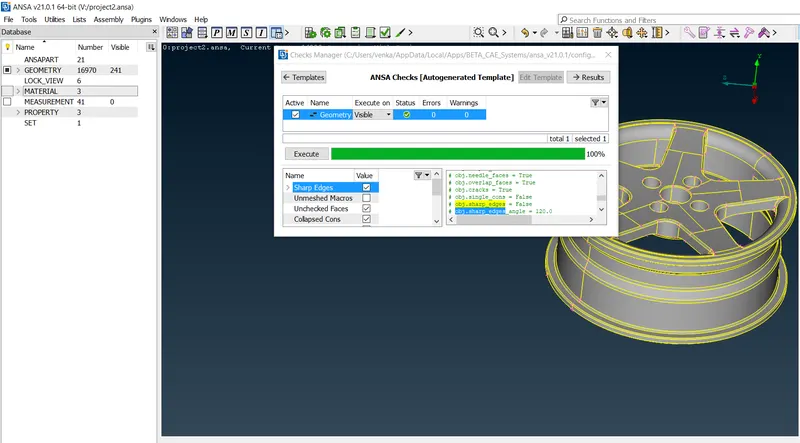
Now set all the components in the separate pids and inorder view the proper manner of each and every individual components seperately.
RIM
This particular Rim component showing the non uniform thickness on the part and we have to mesh this has unstructured mesh with an given Quality criteria.
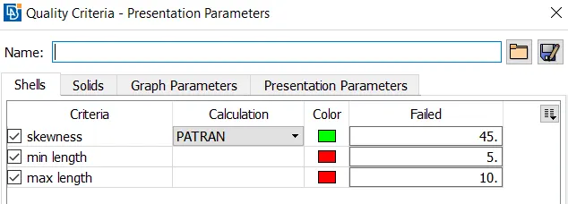
Set the quality criteria and mesh parameters to the component.
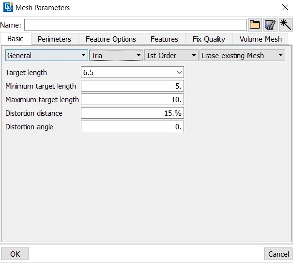
Here we are giving the perimeters target length to the component in an Mesh Deck.
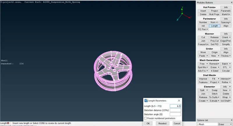
Now mesh the component with the help of spot mesh or best option with the element type as a Tria.
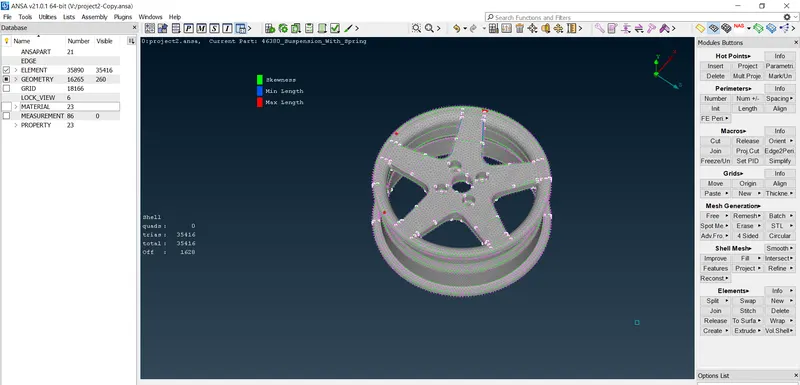
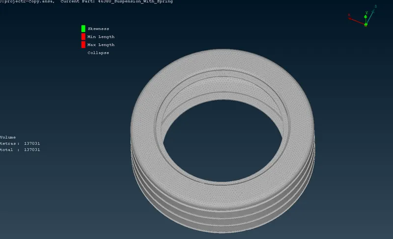
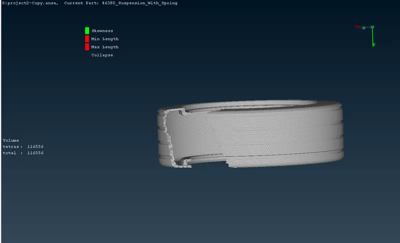
Once this surface meshing is done on the particular component,we have to define the volume mesh for the componenet.
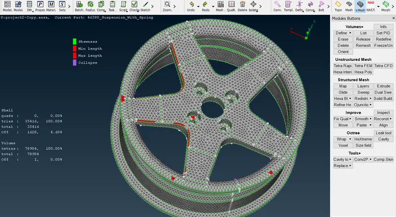
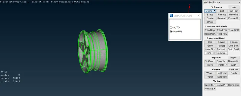
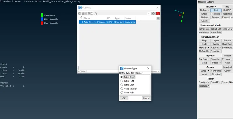
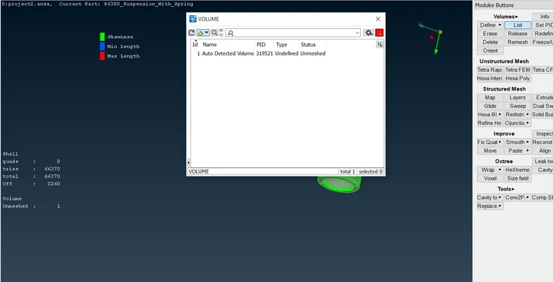
For the volume mesh we have to define an component by manual method, which it creates a list of the detected volume id and we have to right click on the Id it will shows a option list and where we select the Remesh option for producing the tetra rapid or tetra fem volume mesh to the component.

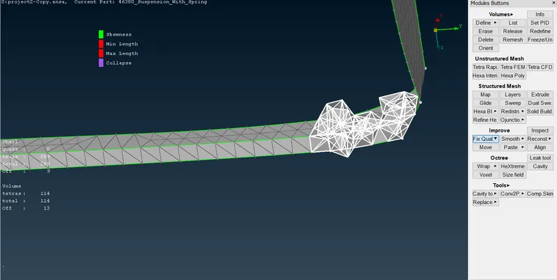
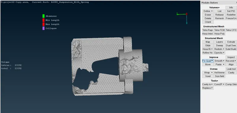
After creating the volume mesh we have to fix the Quality issues by using the Fix Quality option in the Volume Mesh Deck panel.
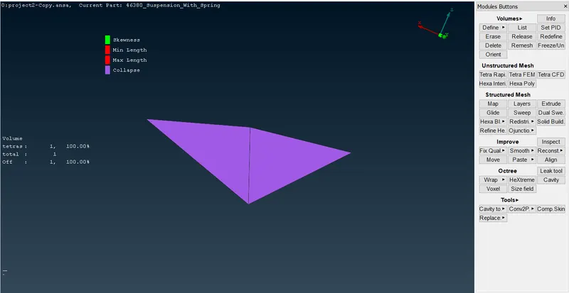
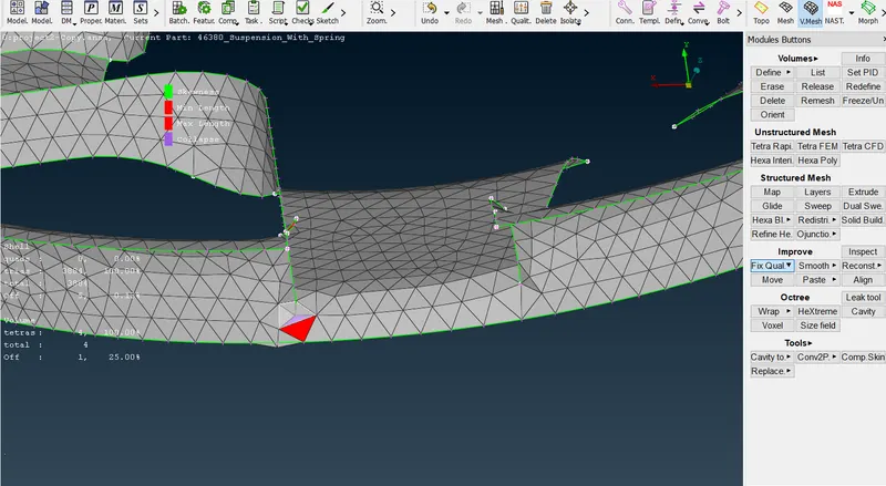
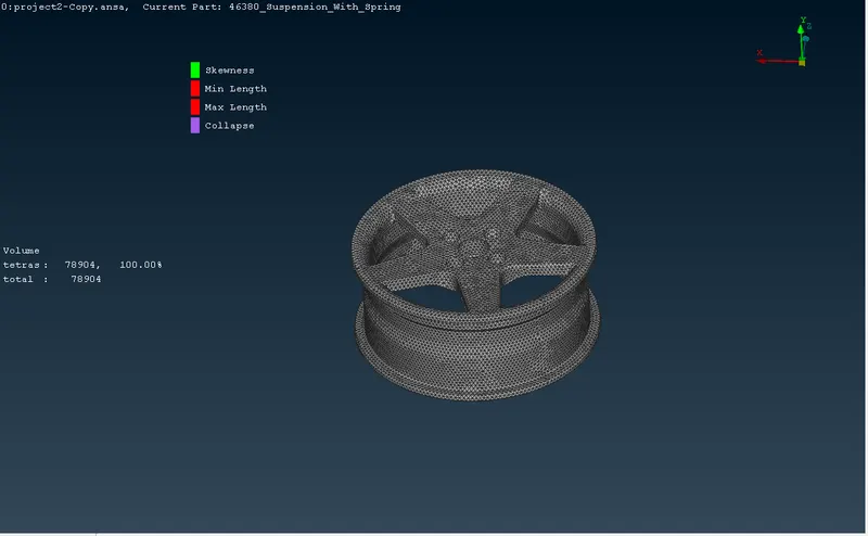
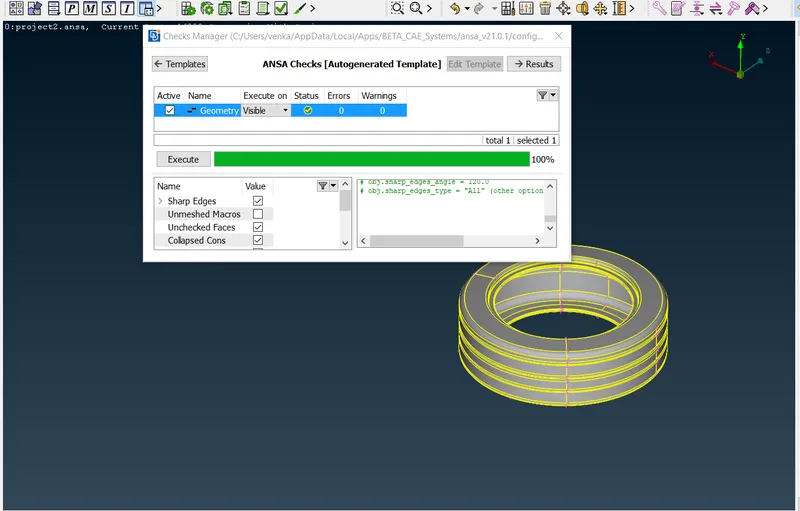
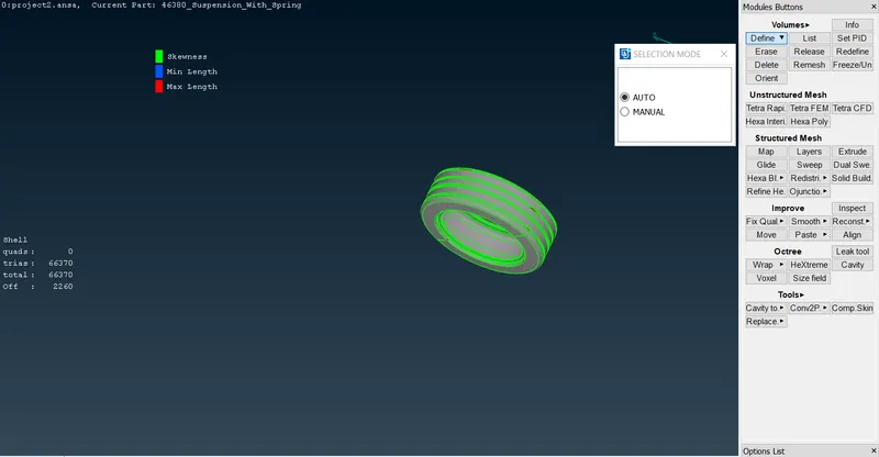
- After Generated the surface mesh with no quality errors.
- Defined a volume and created a PID by selecting the component as shown in below.
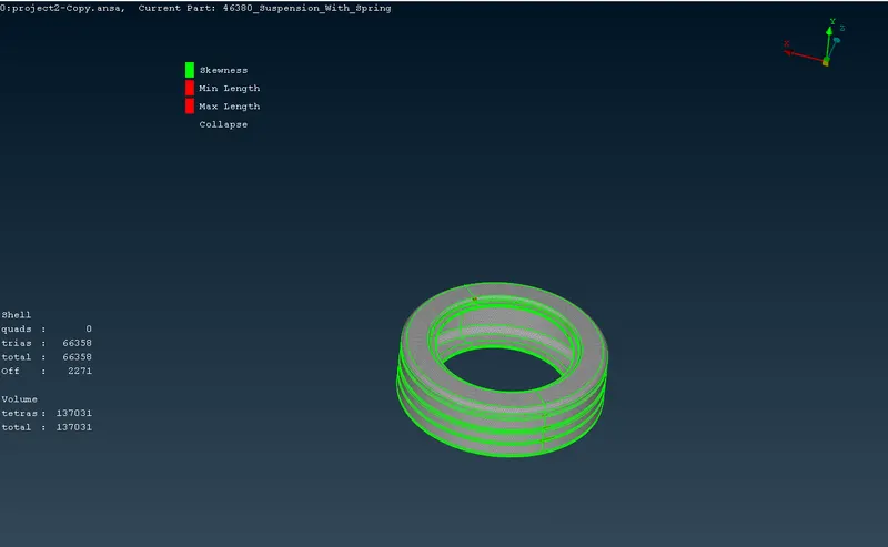
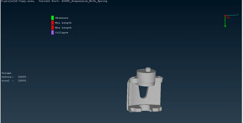
- Now the volume was created, the mesh was generated inside that volume using Tetra Rapid algorithm or Tetra Fem method.
- After the volume mesh is generated, it has to pass the quality criteria of Tet Collapse elements.
- By using the NOT option Hide the selected geometry entites and see the generated unstrctured mesh inside the volume of the component.
Now we have to represent this solid spring with an 1D CBAR element.
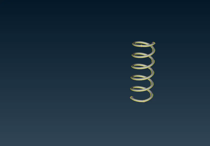
Generate a middle curve for the spring by selecting the lines of an curve and by conform the middle option it will creates a curve.
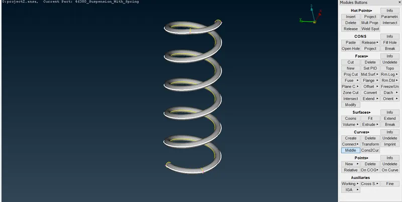
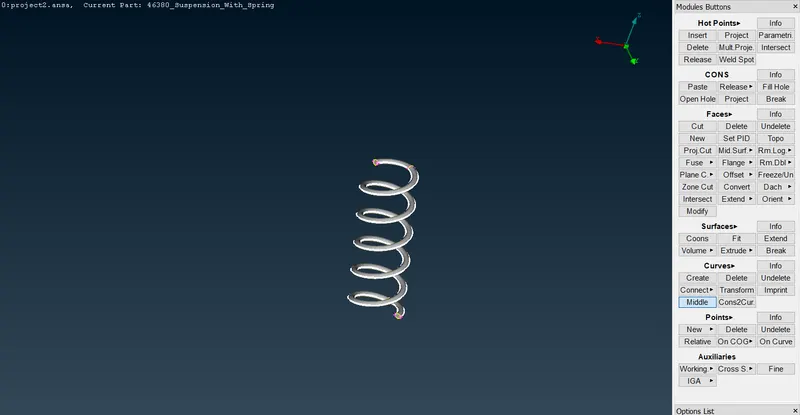
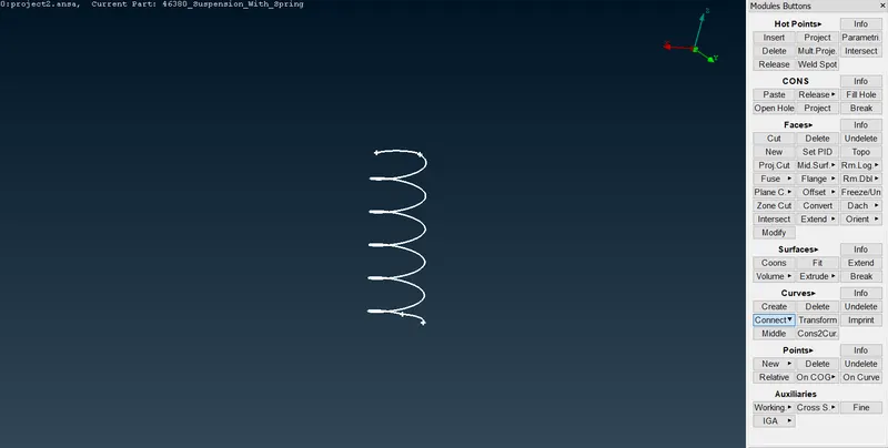
Connect the curve into a single curve . By using the connect multi option in curves.
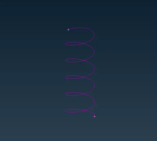
Create a COG point for the curve to define the orientation.
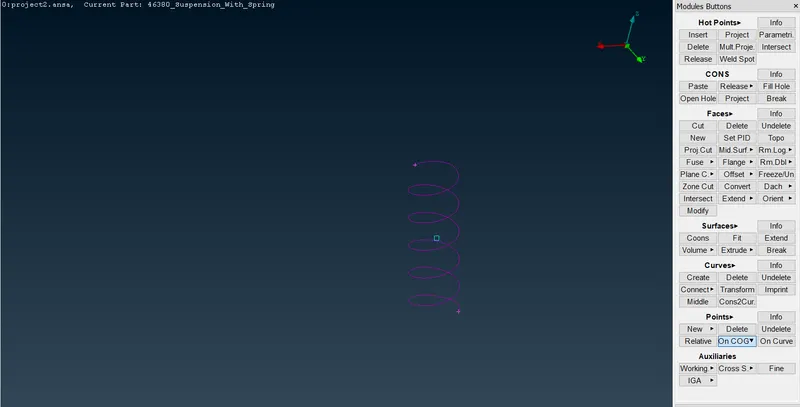
Select the CBAR element and Change the selection type to the curve box.Select the curve and give the middle mouse click
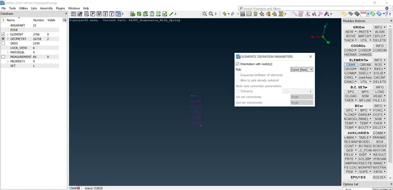
select the orientation node and specify the element length. In this case, The Element length is taken as 3 mm.
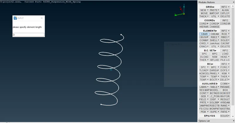
After Specifying the element length as 3 mm, Do middle mouse click and define a pid by creating a new PID.
After that, assign the cross sectional Diameter of the spring element.
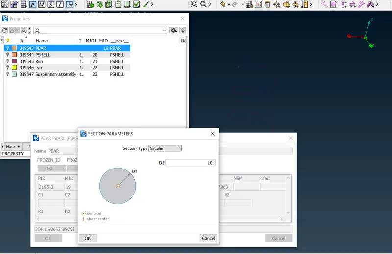
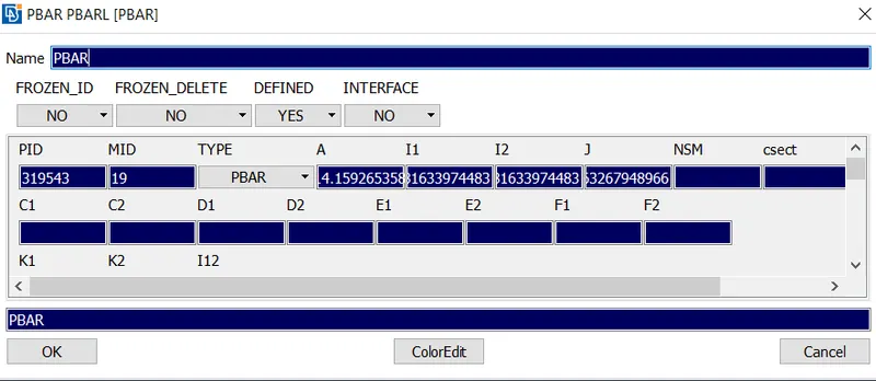
It will calculate the cross-sectional area and moment of inertia.
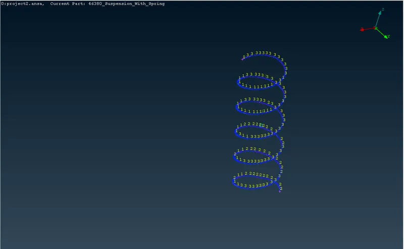
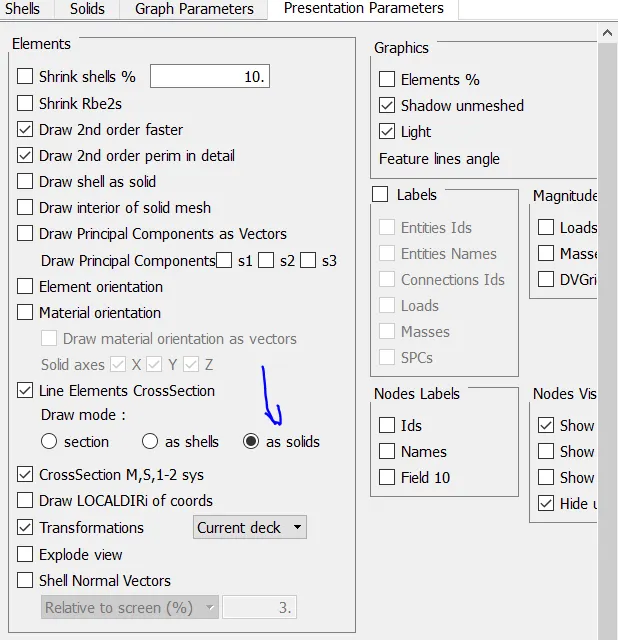
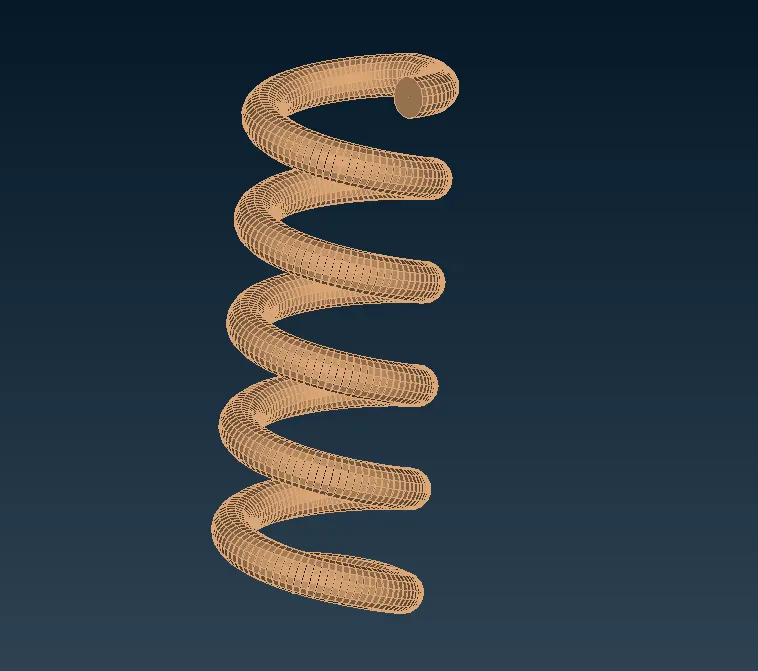
To see the representation of 1D bar elements as 3D element, check the box of 1D detailed representation with the solid in quality parameters as shown in the below image.
2D SHELL MESH;
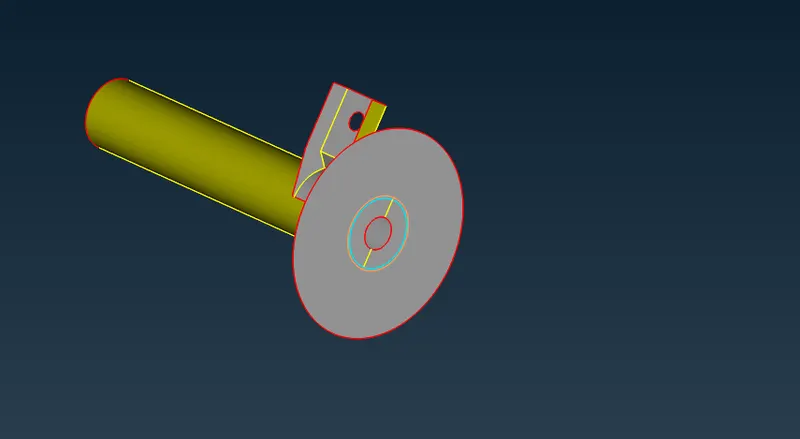
- Mid surfaces was extracted and 2D mesh was generated for the components having thickness below 5mm as per the standards.
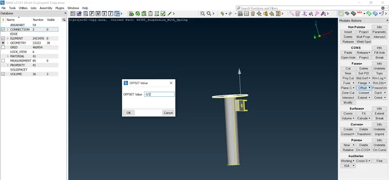
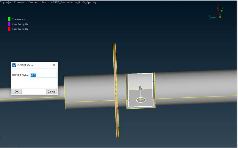
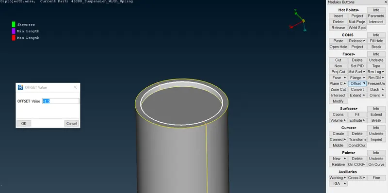
- OFFSET command was used to extract the midsurface manually.
- Set the pids for the generated midsurfaces and mention the thickness values.
- While generating the mesh use Best or Spot mesh option with an mixed elements. Below figure Fig shows the parts below 5mm thickness and which was meshed with the following quality criteria.
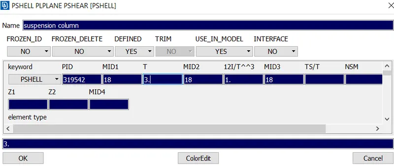
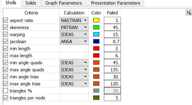
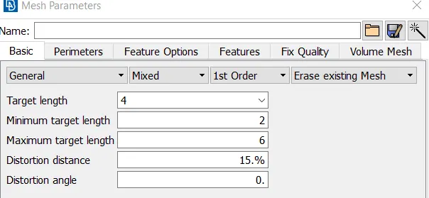
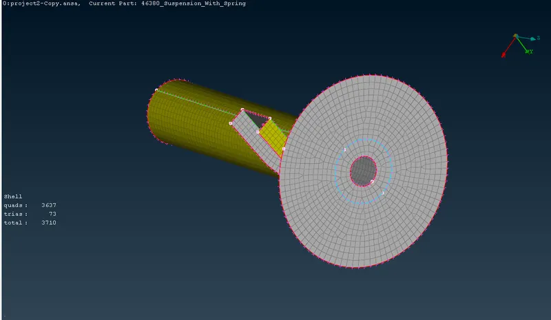
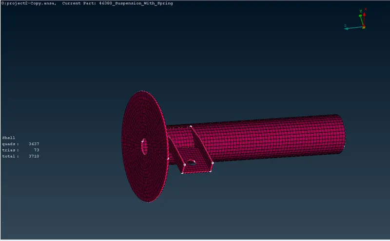
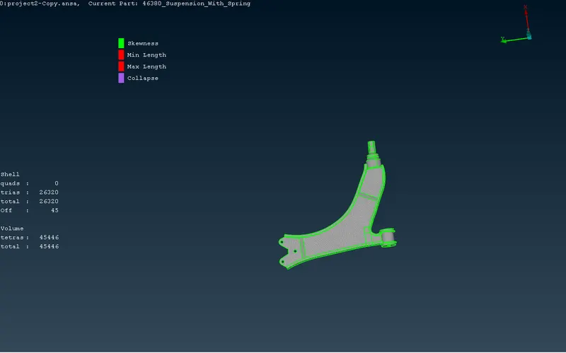
- Generating the Unstructured Mesh for the following Non uniform Thickness Componenets
- Quality criteria for Surface Meshing of Non Uniform thickness components other than Tyre and Rim (Element type: Tria).
Quality Criteria and Mesh parameters for Non uniform Thickness components.
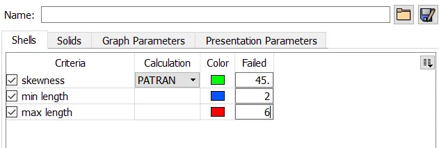
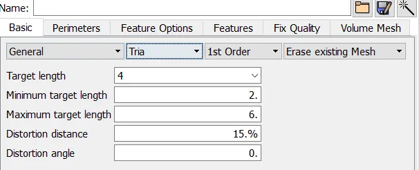
- After setting the quality qriteria and generate the mesh on the particular surface with best option with the tria or ortho tria as an element type.
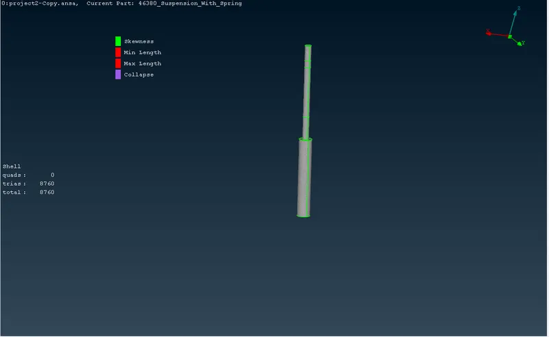
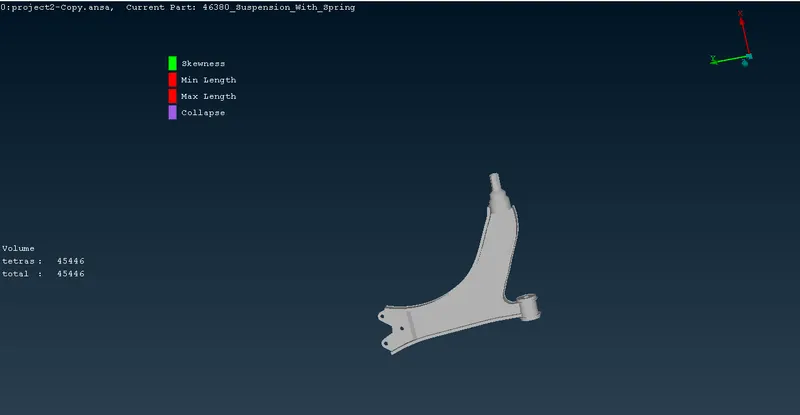
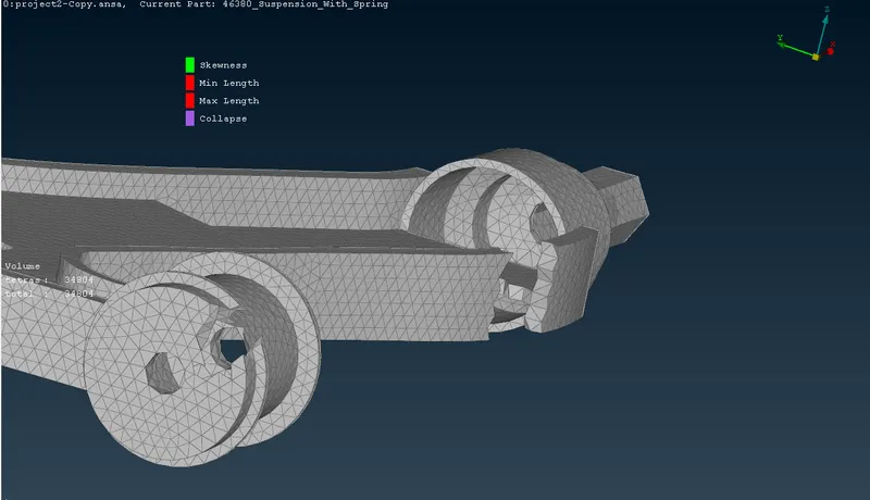
Here, we have define the volume and generate the unstructured mesh by using the Tetra Rapid or Tetra Fem.
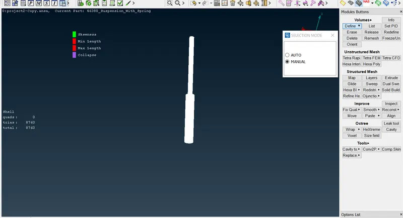
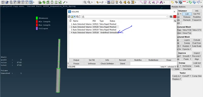
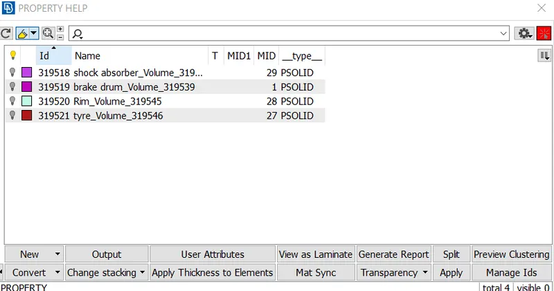
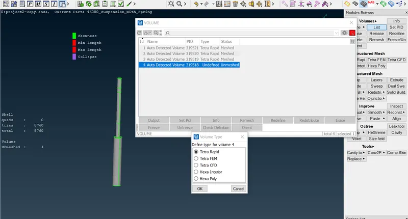
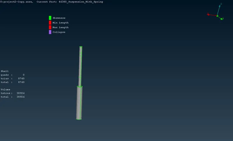
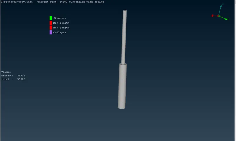
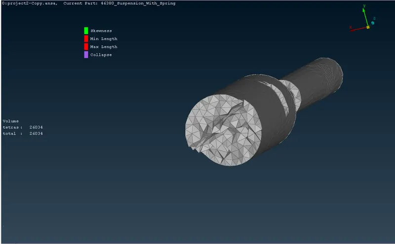
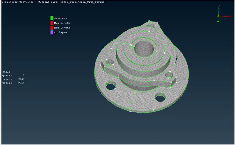
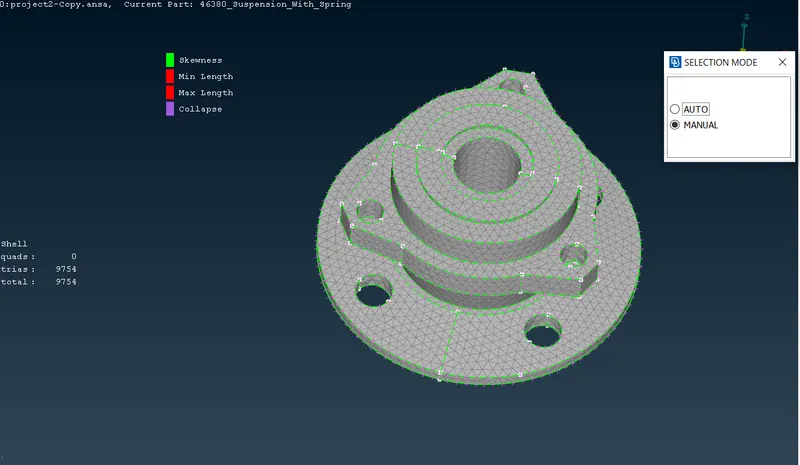
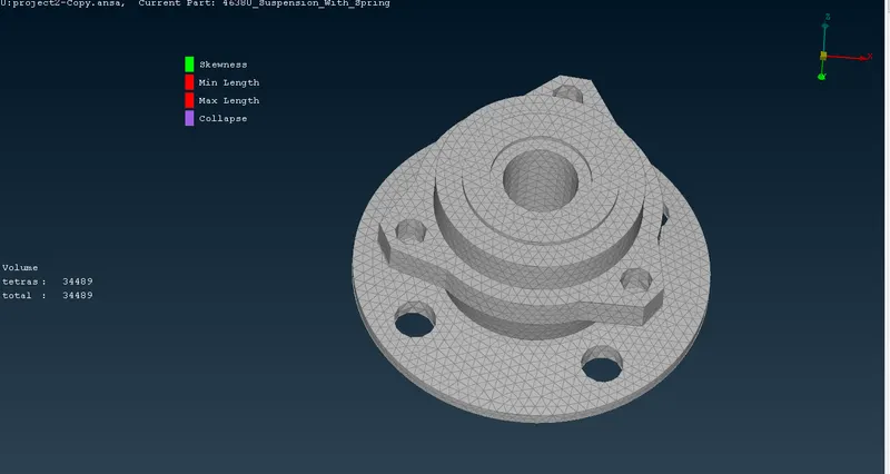
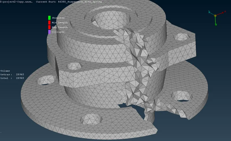
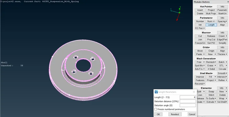
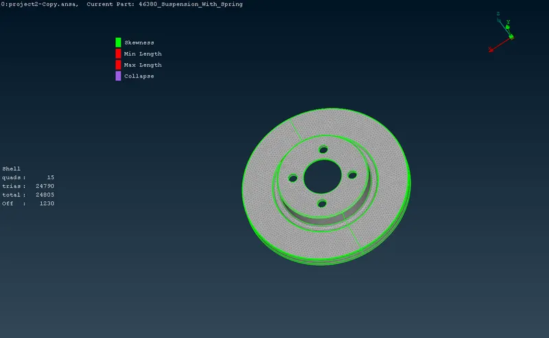
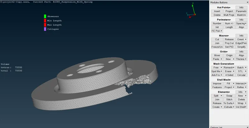
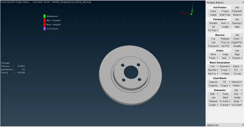
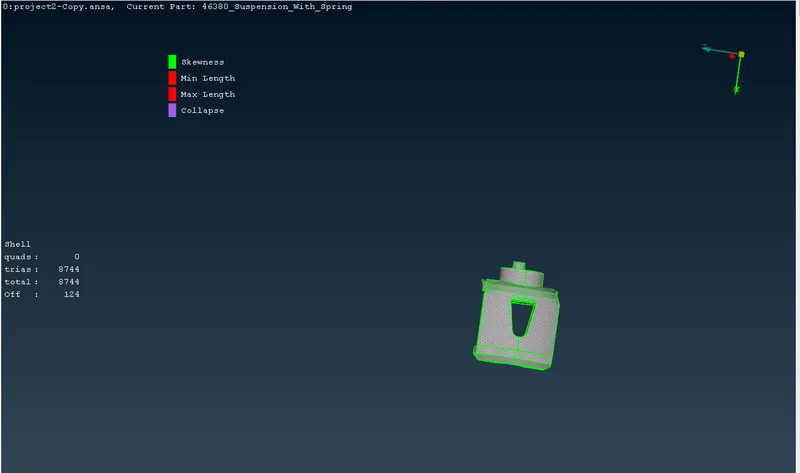
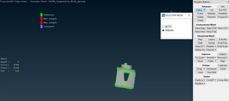
- While defining the Volume mesh, some it will throughs an errors because of the Duplicate or penetration entities form on that particular component.
- Here we getting an Duplicate entities because of the unwanted construction lines which are not properly toggled or removed from the surfaces.
- Remove those unwanted cuts and remesh on that particular surface.
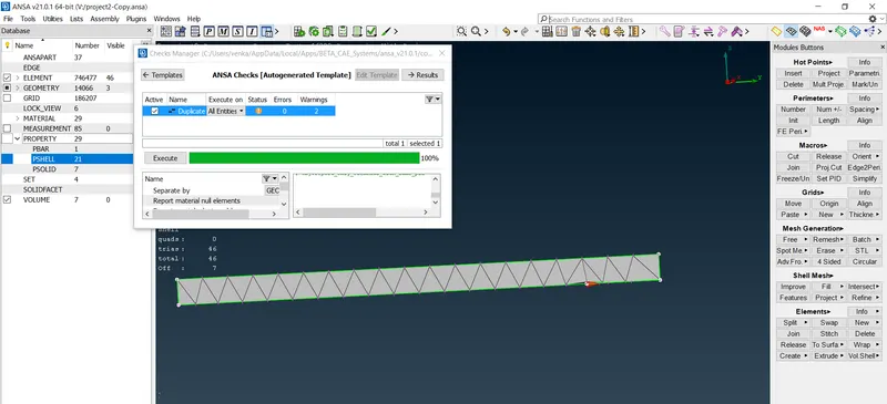
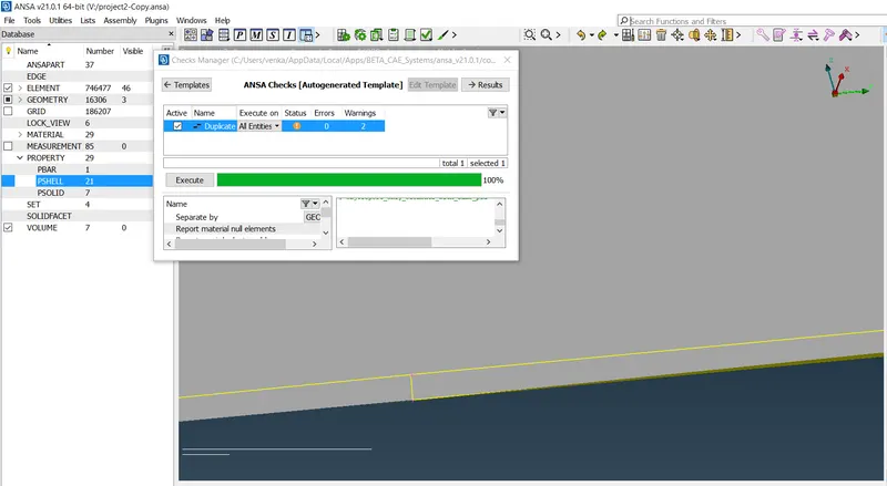
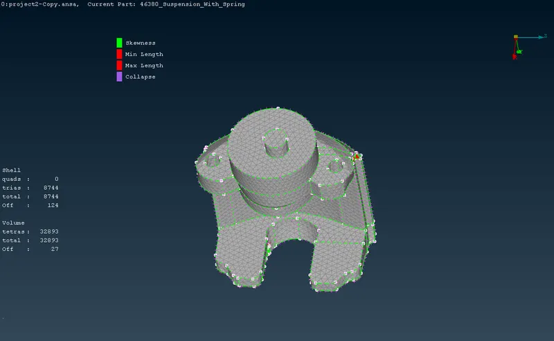
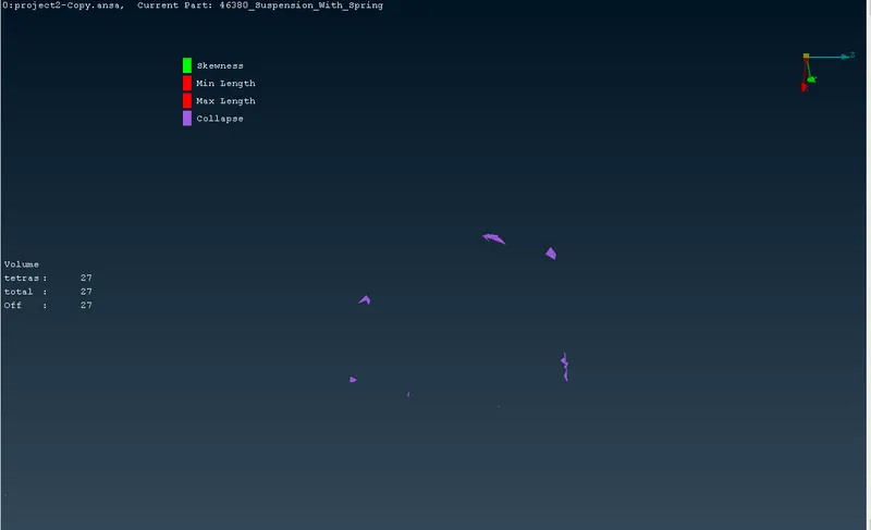
We have to fix the off elements by using the fix quality option on Volume deck.
WELD AND BOLT CONNECTIONS;
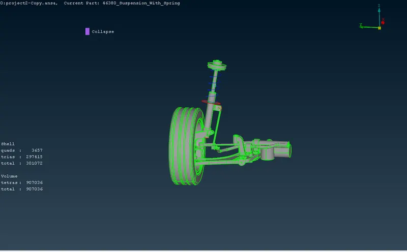
- After completion of all shell mesh and volume mesh we must connect them by using connections like bolt connection, spot weld connection, seam weld connection etc.
- Connections are deployed in the NASTRAN deck module. They will be used and deployed depending on the model.
Seam Weld Connections;
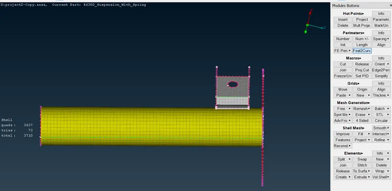
- In order to generate the sem welds, we have to take as reference curve by the component by using an Feat2curve in the Mesh Module.
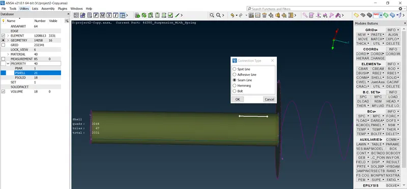
Then the curve is converted to seam line using the Convert> Curves command in the Assembly tab.
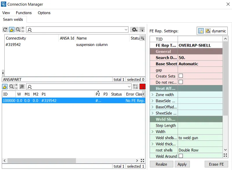
Now open the connection manager and select the p1 and p2 in the component.
Then cahnge the Fe Rep Type as a Over lap shell and assign the values of search distance and base sheet are mentioned. A weld PID is also assigned to the weld FE.
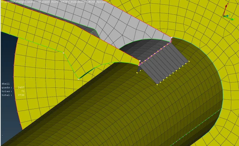
Finally Apply and realise the connection. which is shown in the below figure.
Rigid Connections;
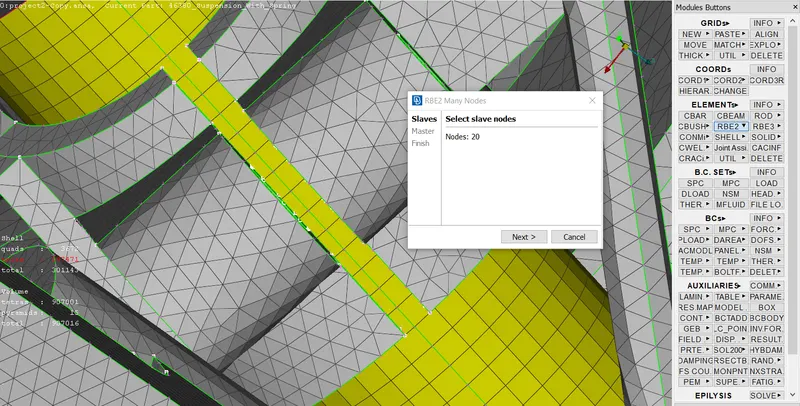
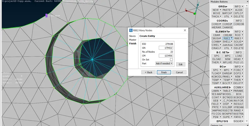
- Generally, bolt representation represents as Rigid connections (Rbe2 elements) which have stiffness and don't allow the moments on that bodies.
- Rbe2 having the two types one is Many node rbe2 and single node rbe2 according to the usage we will use these representations.
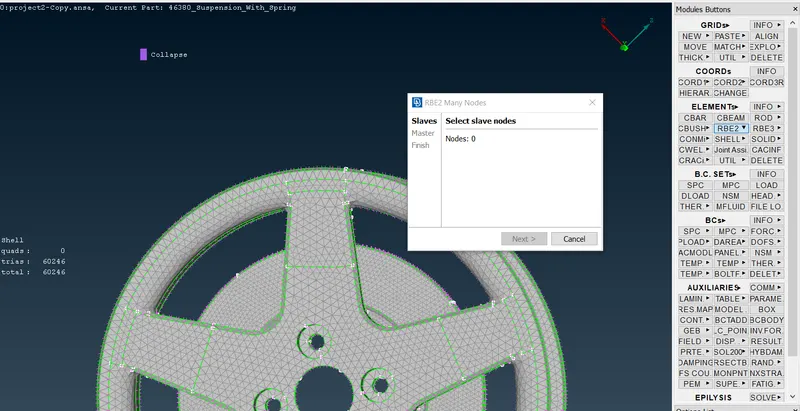
- Below we use the Many node rbe2 elements under the Nastern Deck.
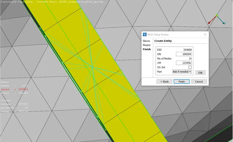
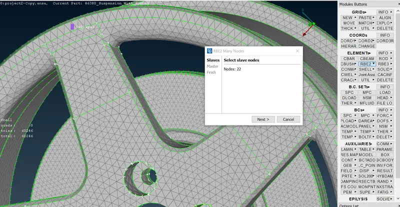
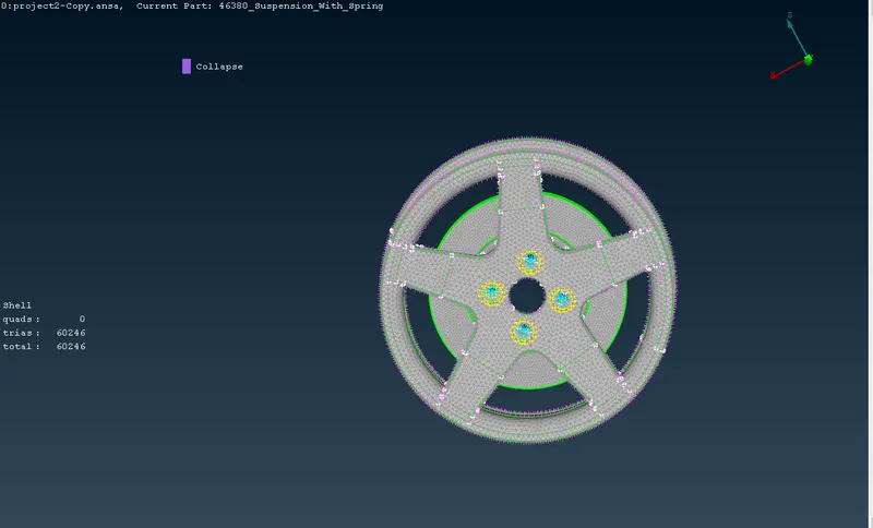
- First select the perimeters of the two holes of the component, it will show the selected nodes in the dialog box and finally by connecting all the slave nodes it will form a Master Node in the centre of the elements.
- At last, it will represent a cluster Rbe2 elements in between the holes.
Transform;
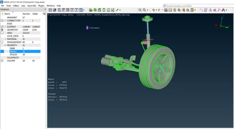
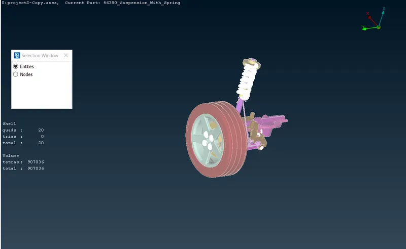
- After completing surface mesh, volume mesh, mid surfacing and connections we have to use transform option in order to create remaining half of the model on the other side.
- Use transform option in the utilities tool bar and select all the entities including connections to generate exact replica of the model on the other side.
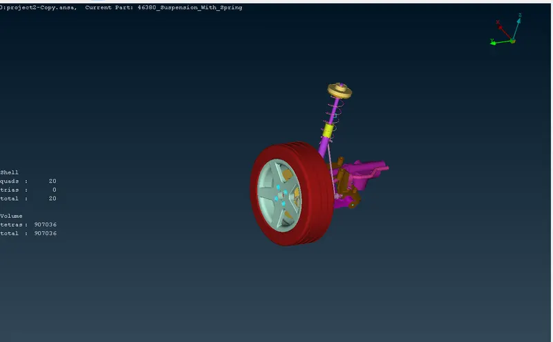
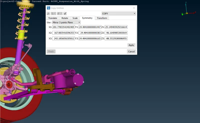
- Now, use symmetry option select the three axis points plane option and select the 3 points on the edges of the component model. These 3 points represent all the 3 coordinates (x, y, z). This helps all the entities to transform on the other side.
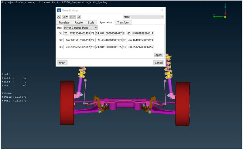
Finally on confirmation click on the Finish option and it will sucessfully completes the symmerty opertaion on the suspension model.

LEARNING OUTCOMES:
- Perform the Topo cleanup on the geometries of an suspension Assembly models.
- Mid-surface extraction to the components which are falling under criteria.
- Assigning property ID's & set the quality criteria parametrs.
- 2D Shell meshing for the Uniform Thickness components.
- Generated the solid meshing for the Non Uniform thickness of the components with an Un structured Mesh and also Defining the Volume Mesh method.
- Error detections on while creating an volume mesh because of the Penetrations and Duplicate elements on the surfaces of the model.
- Resolving tetra collapse & other quality issues.
- Deploying the appropriate connections to the model.
CONCLUSION;
- In this challenge, I have meshed the given suspension assembly components with the solid mesh(element type as Tria and Ortho) and 2D shell elements(element type as mixed) according to the Quality parameters.
- Given the connections to the model and Symmerty operation has done on another side of the Model.
Here I'm attaching the model link below;
https://drive.google.com/file/d/1u2KaOYZNfAa_7_S2vNL0pnSk4dVJch36/view?usp=sharing