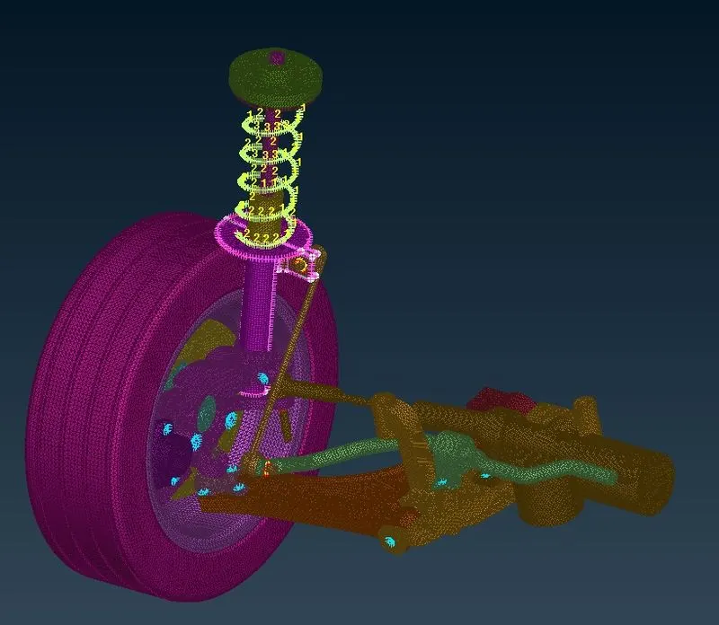
Meshing on the suspension Assembly
Aim: To Perform the following on the given Rear Wheel Assembly,
i. Geometry Clean-up.
ii. Extract Midsurface for components with thickness less than 5mm.
iii. Mesh the Component as per the given quality criteria and convert to 3D Tetra mesh
iv. Mirroring the component.
Quality Criterion:
Quality Criteria for Surface Meshing of Tyre and Rim (Element type: Tria) :
|
S.No |
Quality Criteria |
Value |
|
1 |
Target/Average length |
6.5 |
|
2 |
Minimum Length |
5 |
|
3 |
Maximum Length |
10 |
|
4 |
Skewness |
45 |
Quality criteria for Surface Meshing of Non Uniform thickness components other than Tyre and Rim (Element type: Tria) :
|
S.No |
Quality Criteria |
Value |
|
1 |
Target/Average length |
4 |
|
2 |
Minimum Length |
2 |
|
3 |
Maximum Length |
6 |
|
4 |
Skewness |
45 |
Quality Criteria for Volume meshing of all Non Uniform thickness components (Element type: Tetra Elements):
|
S.No |
Quality Criteria |
Value |
|
1 |
Tet-collapse |
0.2 |
Quality criteria for Mid surfacing of Uniform thickness part which has thickness less than 5 mm (Element type: Mixed elements) :
|
S.No |
Quality Criteria |
Value |
|
1 |
Target/Average length |
4 |
|
2 |
Minimum Length |
2 |
|
3 |
Maximum Length |
6 |
|
4 |
Aspect |
3 |
|
5 |
Warpage |
15 |
|
6 |
Skewness |
45 |
|
7 |
Jacobian |
0.7 |
|
8 |
Minimum Quad Angle |
45 |
|
9 |
Maximum Quad Angle |
135 |
|
10 |
Minimum Tria Angle |
30 |
|
11 |
Maximum Tria Angle |
120 |
Model:
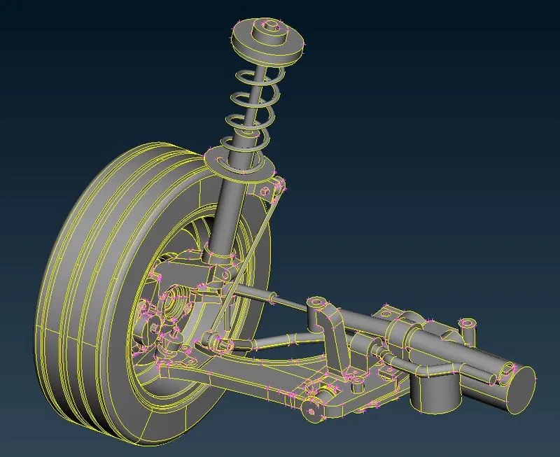
Procedure:
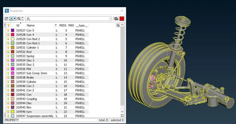
1. Import the Model and set PID for each sub component as shown.
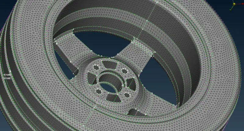
2. Clean up the geometry as per requirement for tyre and rim. Mesh the surface with trias(Flat Surfaces) /Orthogonal trias(Curved surfaces) as shown. Elements are checked for quality and fixed if they are failing.
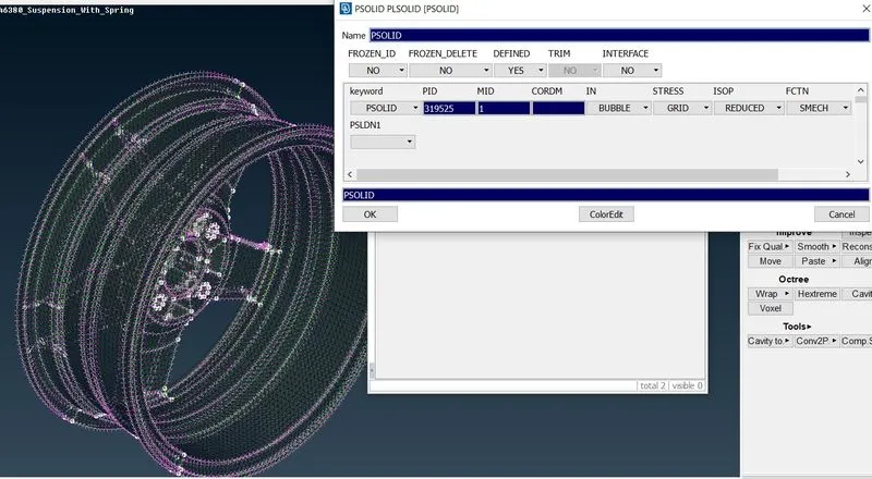
3. Volume is defined for Tyre and rim separately using Volumes - Define - Manual and selecting the component and defining the PSOLID as shown.
4. Select Unstructured Mesh - Tetra Rapid or Tetra FEM - Select Volume to create volumetric mesh as shown.
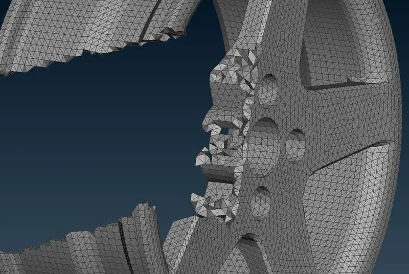
5. Check for Tet Collapse and fix the elements if they are failing for quality.
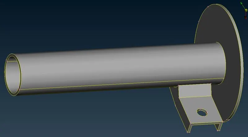
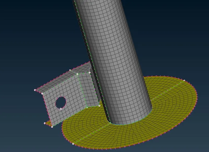
6. By Measuring the thickness few sub components have a thickness less than 5mm for which mid surface is extracted and meshed as per the given quality criterion as shown.
Mid Surface with Mesh
7. Other Subcomponents are meshed as shown below with the given quality criterion mentioned in the begining.
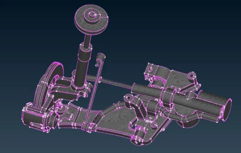
8. Volume is defined separately for each sub component and volumetric mesh is generated using Tetra Rapids or Tetra FEM.
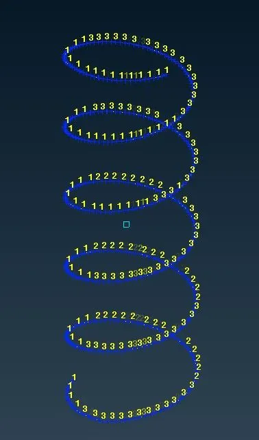
9. Spring Sub Component is represented as 1D CBAR elements as follows.
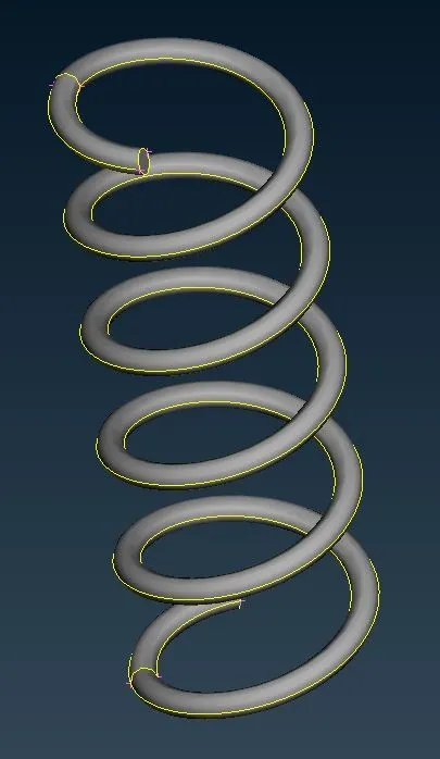
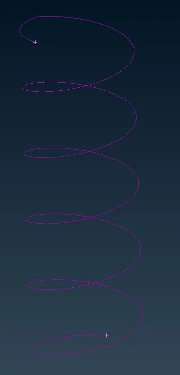
. Middle Curve is generated using Curves - Middle - select first set of feature line and next second set to generate as shown.
. COG point is defined for the orientation and in NASTRAN - Elements - CBAR is selected as shown.
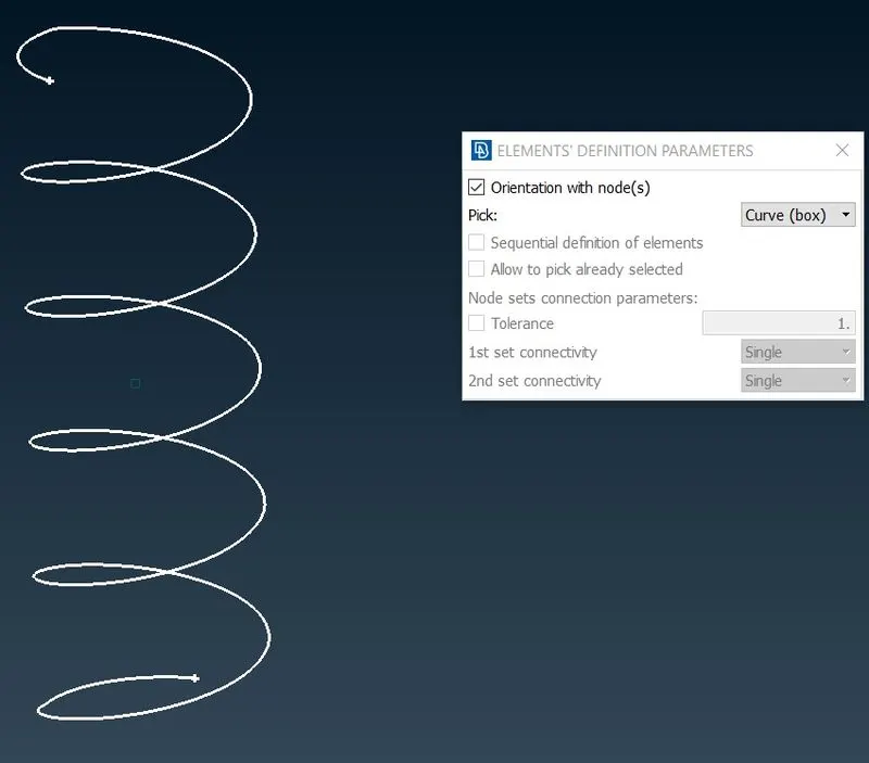
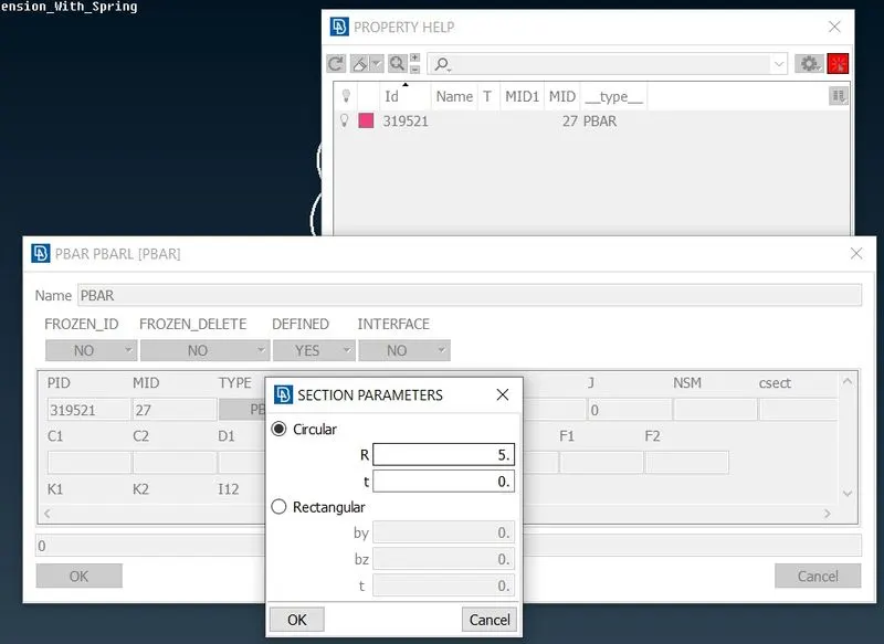
. Enter the element length as 3 mm and create a new PID. Cross Section radius of spring has to be defined in the PID as shown.
. The 1D CBAR elements are as shown.
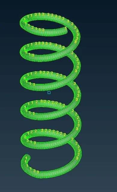
. To represent the 1D elements as solid elements go to Quality criteria - ckeck Line Elements CrossSection - check as Solid.
Connections:
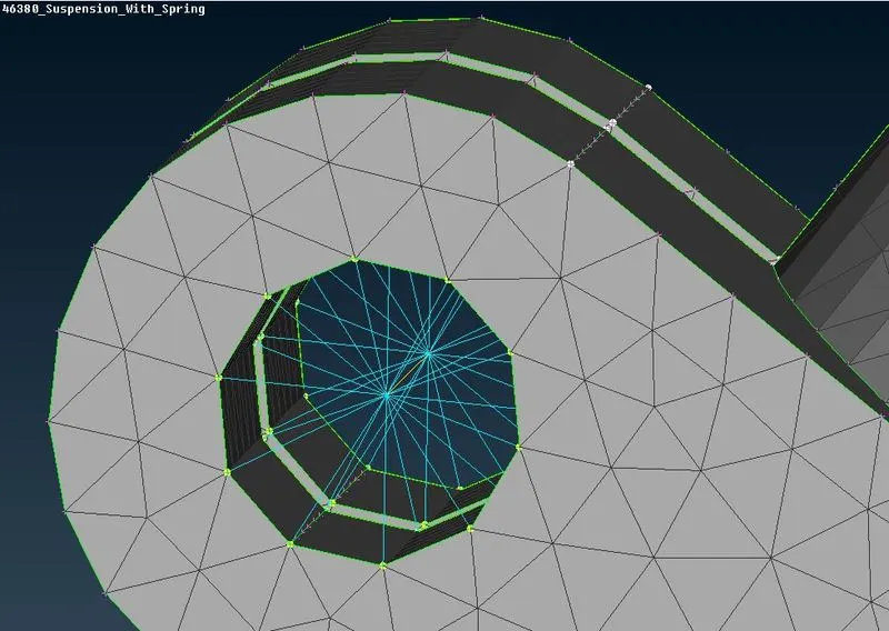
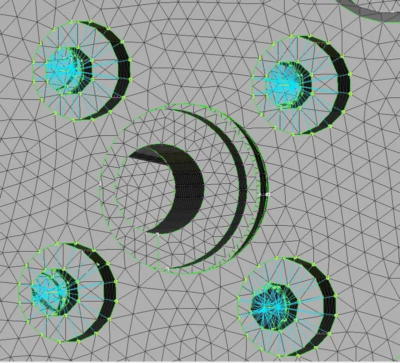
1. Bolt holes are connected using cluster RBE2 and 2 Node RBE2 where ever necessary as shown.
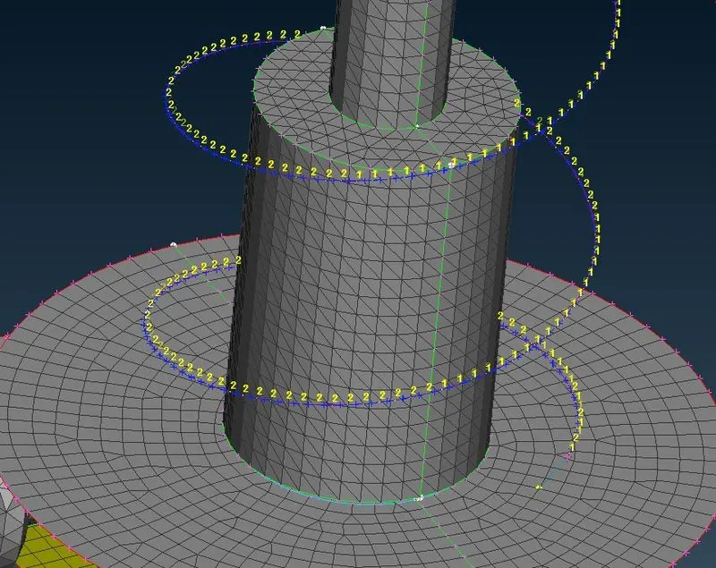
2. Spring 1D CBAR element is connected using RBE3 element as shown.
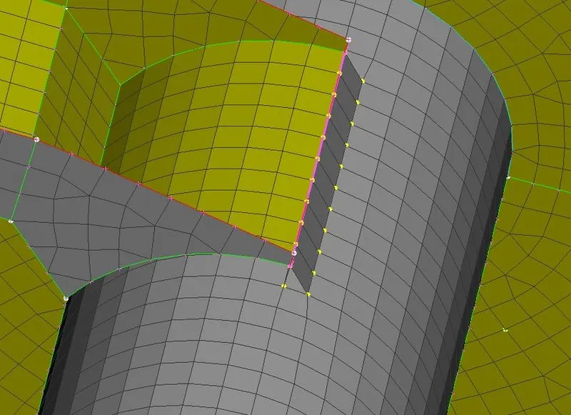
3. Seam Weld Connection is deployed between two sub components midsurface as shown.
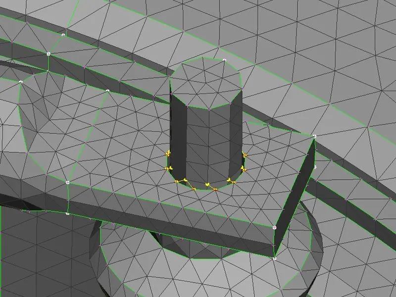
4. Remaining necessary components are rigidized using two node RBE2 elements as shown.
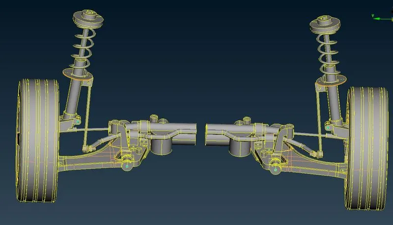
10. The entire Rear Wheel Assembly is Reflected as shown.
Conclusion:
Rear Wheel Assembly is meshed and volumetric mesh is generated as per quality criterion. Appropriate connections were deployed and the assembly is reflected as required.