Project - 2 - Meshing on the suspension Assembly
WEEK 6 CHALLENGE
AIM
To mesh the given rear wheel assembly model, with tetra and 2 D elements, and deploy connections for the components.
PROCEDURE
- It is observed that most components in the model have a very large thickness, so we will proceed with generating a mesh with tetra elements for most of the component.
- We split the model into different Pids using iNot Pid Region option.
- Check the components for geometrical errors using the tools check geometry option.
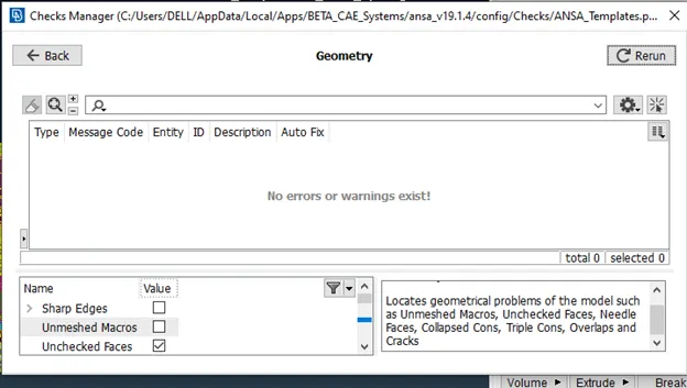
Figure 1 - First, we start with the component with a thickness of 3 to generate the mid surface as shown in figure 2.
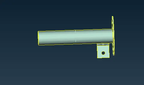
Figure 2 - We use the offset command to generate the mid surface.
Note: It is required to extend the cylinder and result with a triple con on the mid surface.
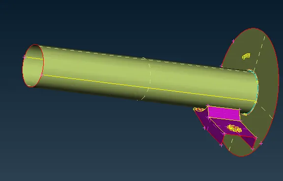
figure 3 - Now, we move on to mesh the generated mid surface according to the given Quality criteria in table 1.
|
Criteria |
Value |
|
Target Length |
4 |
|
Aspect |
3 |
|
Skewness |
45 |
|
Warping |
15 |
|
Jacobian |
0.7 |
|
Minimum length |
2 |
|
Maximum Length |
6 |
|
Angle Tria |
30 minimum, 120 Maximum |
|
Angle Quad |
45 minimum, 135 maximum |
Table 1
- The final generated mesh is shown in figure 4 for the component.
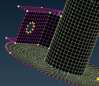
Figure 4
- Now we move to the solid meshing of the tyre and rim component.
- There are several small fillet areas in this component for which elements will fail for the Quality criteria and hence need to be defeatured as shown in figure 5.
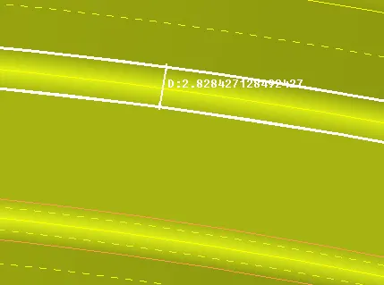
Figure 5 - We use the dach divide face option to defeature these regions, using the normal dach option will lead to the deleting of the fillet feature which while acceptable is not preferable.
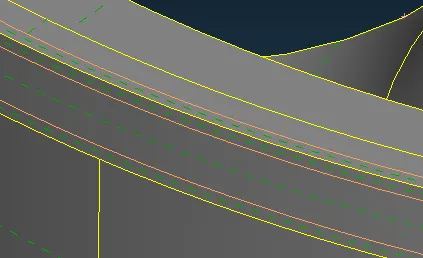
Figure 6 - There are certain groove features on the tyre that will not pass the criteria, however, since these are critical features and are angled at 90 degrees defeaturing is not possible as it would lead to the loss of the entire feature.
- In such cases, we accept the off elements in favour of capturing the feature.
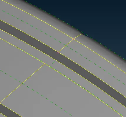
Figure 7 - The criteria of the mesh are given in table 2.
|
Criteria |
Value |
|
Target element length |
6.5 mm |
|
Skewness |
45 |
|
Minimum Length |
5 mm |
|
Maximum Length |
10 mm |
Table 2
- We generate the mesh with best mesh option with tria elements.
- It is to be noted that curved features are captured better with ortho tria elements but take a longer solver time.
- In the rim, component features fail despite having sufficient length for elements.
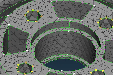
Figure 8 - This is because to capture 2 rows of elements, the target element length needs to be lowered with which we can capture the element better.
Note: we will still have a few off elements that we accept to capture the feature accurately. - After the tyre and rim components, we move on to the other components which have different criteria shown in table3.
|
Criteria |
Value |
|
Target Length |
4 mm |
|
Skewness |
45 |
|
Minimum Length |
2 |
|
Maximum Length |
6 |
Table 3
- Before we start meshing, it is important to defeature certain features such as those shown in figure 9 and figure 10 to clear the element criteria.
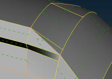
Figure 9
Figure 10
- Features like the ones shown in figure 11 had to be fixed since ansa pasted the cons of the slope which is unacceptable for meshing Quality
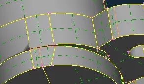
figure 11
- Fillet features such as the ones shown in figure 12 were defeatured using the dach divide face option to solve off elements.
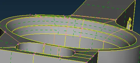
Figure 12 - The base of these fillets shown in figure 13 was defeatured, we cannot use dach divide face or create a middle con in this case since such defeaturing will lead to improper capturing of the features(excessive loss of volume)
It is observed that removing the base still captures the feature properly with the mesh.
figure 13
- The feature shown in figure 15 had to be defeatured as shown, note the cut slope was created to help with approximate capturing of the curved section.
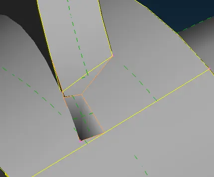
Figure 14 - These curved features are not defeatured and captured as is since they are considered critical features. However, if they fail collapse criteria after volume meshing they must be defeatured.
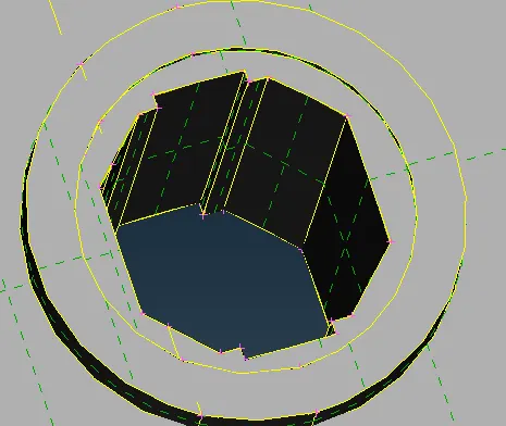
Figure 15
- After this, we can move on to solid meshing
- For most of the curved features, it is better to proceed with ortho tria elements to capture them better but since we are required to use tria elements we use them for curved features as well. It is recommended to always use ortho tria meshing for curved features for better mesh.
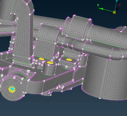
Figure 16 - After generating the solid mesh, we define the volume for each component and create tetra rapid elements for the defined volumes.
- The mid surface components do not have their volumes defined.
- The final meshed component is shown in figure 18, after generating the volume mesh we check for a collapse error of 0.2 for the generated volume.
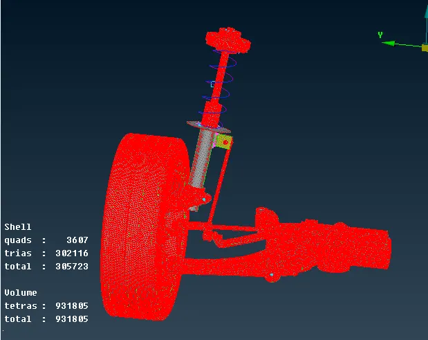
Figure 17
- After completing the mesh generation we now move to deploy connections.
- We use rbe2 elements and a seam weld for this.
- The connection manager may not work properly due to the large number of elements involved and hence we need to manually deploy many node rbe2 elements and 2 node rbe2 elements instead.
- In the case of the holes connecting the rim and wheel to the suspension assembly, we use many node rbe2 for each hole and connect the 3 master nodes with 2 different 2 node rbe2 elements.
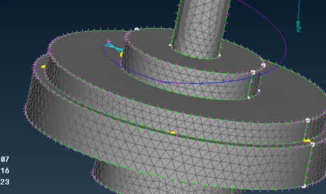
Figure 18
- We can connect 2 different components by creating 4 different 2 node rbe2 elements connecting the 2 elements.
Figure19
- A seam weld connection is used to create a connection between the cylinder and the component as shown in figure 21.
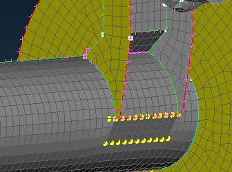
Figure 20
- For holes connecting 2 different components, we use many node rbe2 and 2 node rbe2 connections as shown in figure 22 and 23.
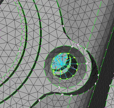
figure 21
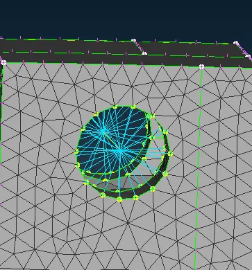
Figure 22
- Finally, we generate the spring component as a Cbar element.
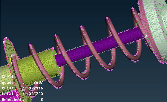
Figure 23 - For this, we first create a middle curve throughout the entire spring after which we generate a 3d point using the points on curve option under the topo module.
- Now under the Nastran deck, we choose the cbar element, choose curve box and orientation with node option.
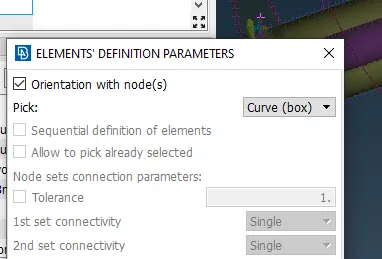
Figure 24 - Select the curve, middle click and then select the point after middle clicking again give element length as 3mm and proceed.
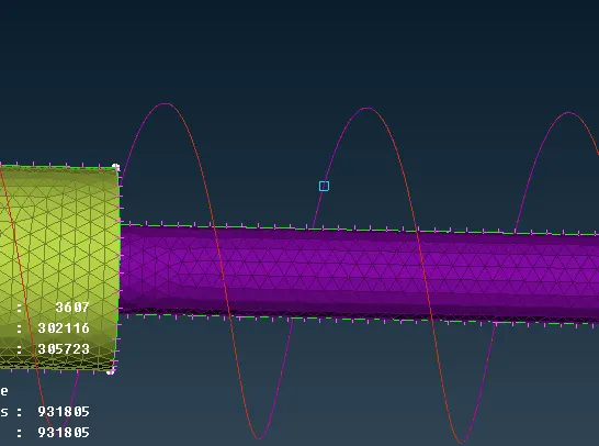
Figure 25 - Define a Pid by creating a new PID, under the area of cross-section, shift+/ then proceed to give radius as 5mm.
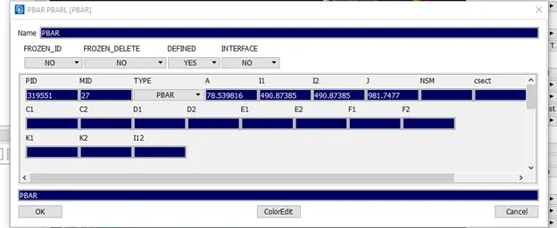
Figure 26
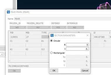
Figure 27
- The generated connection can be viewed by enabling line connections as a shell option
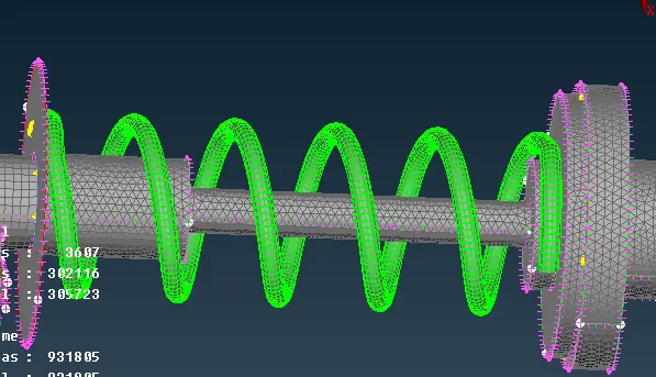
Figure 28 - We connect the spring by using many node connections as shown in figure 30.
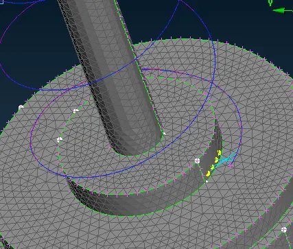
Figure 29
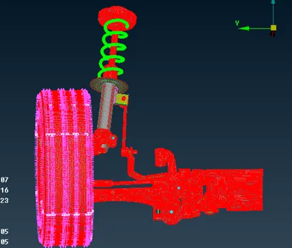
Figure 30
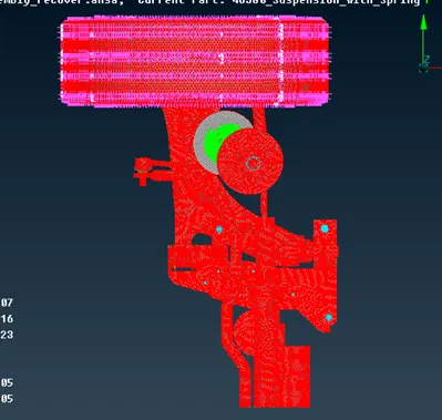
Figure 31
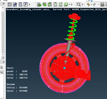
Figure 32
Learning Outcomes
The following skills were learnt and practised during this challenge.
- Connections using Nastran Deck
- Solid and mid surface meshing
- Rbe2, Cbar, Seam weld connections were practised
- Connections using 2 node elements.
- Modelling a spring as a 1 D cbar element.
Conclusion
The given model was meshed under strict criteria successfully, certain elements failed but the defeaturing needed to solve them was unacceptable so we accepted them despite failing criteria to capture features more accurately.
After meshing connections were deployed in the form of rbe2, cbar and seam weld elements.