Project - 2 - Meshing on the suspension Assembly
AIM: To perform the geometry check , Midsurfacing , Meshing and Volumetric meshing and connection on the given assembly of Rear suspension..
PROCEDURE:
- The suspension has been a very important component in automobiles. The most basic purposes of suspension for a system is to prevent the body of vehicle from the hitting the ground and to keep the tires in contact with road.
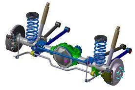
- The Rear suspension is shown below. We have to perform the geometry check up first so there wont be any errors. And we can perform the other operation smoothly.
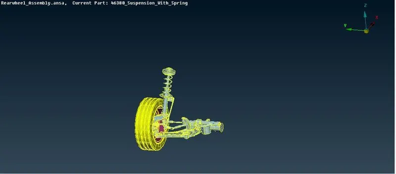
- So this how the rear suspenison look. Its a symmetry thats why only half part is shown.
- Now the geometry checkup is done and errors are removed using autofix.
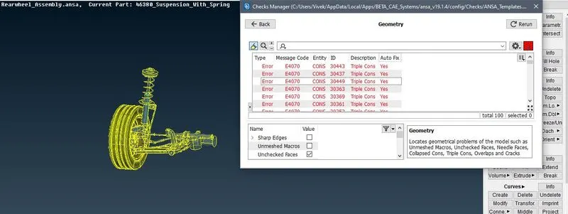
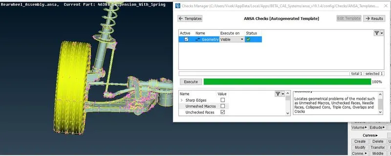
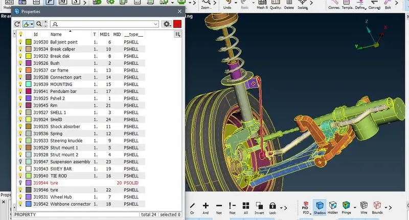
- Now lets assign the PID to each component so it will be easy to perform the midsurfacing and meshing accordingly. For assigning the PID we will use TOPPO module in that FACES>SET PID
- So the Assigned PID as shown below:
- Now we will perform the midsurfacing on some component and then perform the meshing operation on it.
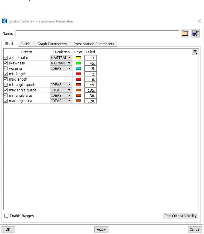
- First we assign the quality criteria for the component. Which is shown below:
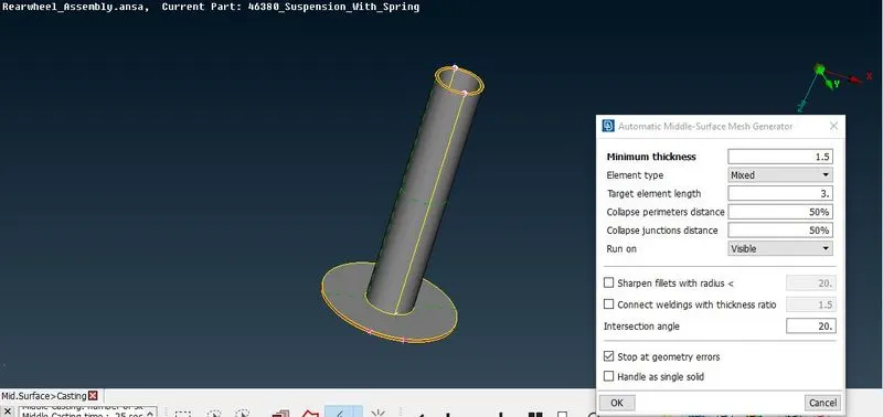
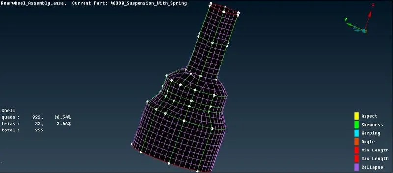
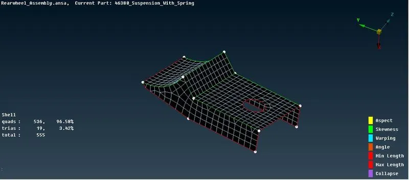
- As we will use the mixed meshing on the midsurafaces. For that we will use the different types of method for the good mesh flow. Its shown below:
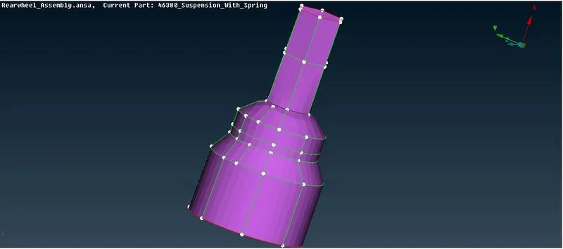
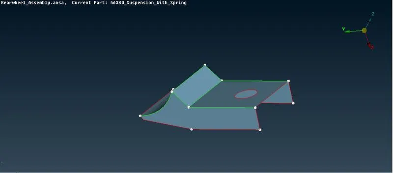
- For the following component I used casting method as the components are not complex. For that goto the TOPPO module then FACES>MIDSURF.>CASTING .
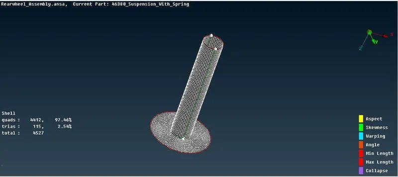
- And all the component are done with same process as shown below:
1.
2.
3.
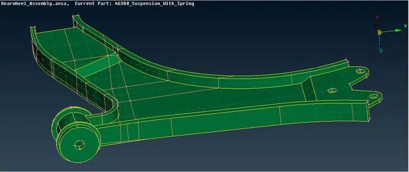
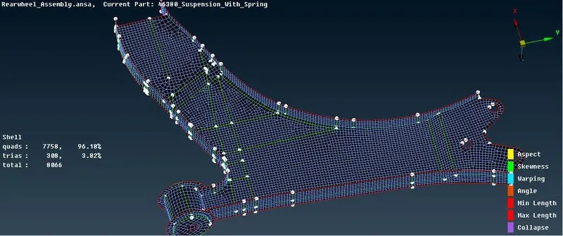
- So after the part is done we will perform the volumetric meshing first, so for that first assign the quality criteria and perform the batch meshing on the TYRE and RIM
- We will perform batch mesh on it for that first assign the TYRE adn RIM as seperate part using model broweser. The reason for doing batch meshing is that batch mesh automatically perform the topology cleanup and perform the meshing.
- Then go to the batch meshing and create new scenario and assign the quality criteria and and click on run. All the process is shown below:
Quality Criteria:
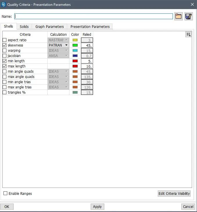
Batch Meshing:
- TYRE
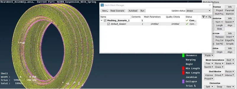
- RIM
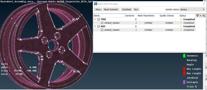
- Now the meshing is done its time to perform volume meshing on it. For the go to the Volume mesh module
- Then select VOLUMES>DEFINE>MANUAL and then assign the sepererate solid shell to the part.
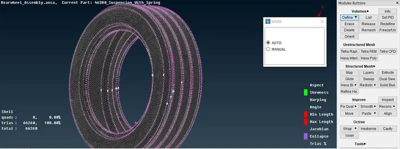
- Then go to VOLUME>LIST and them right click on the give tab and perform the remesh operation after that select the type of unstructured mesh you want. it is shown below:
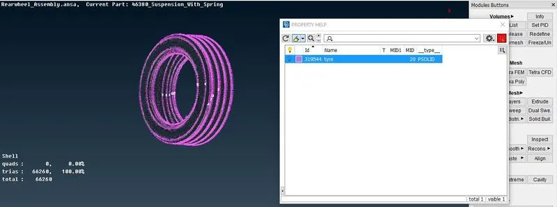
- The final coponent will look like this :
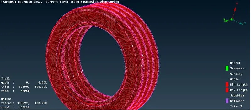
- Same process is to be done with the rim and the RIM will look like as shown:
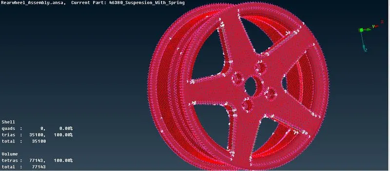
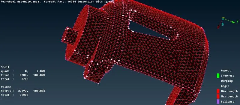
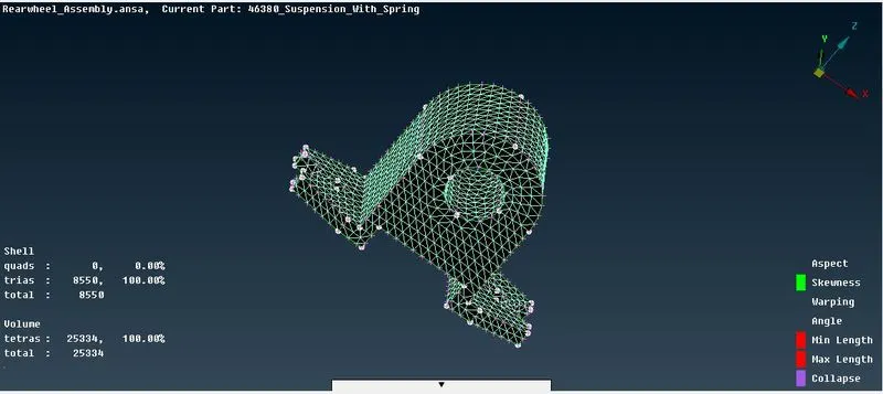
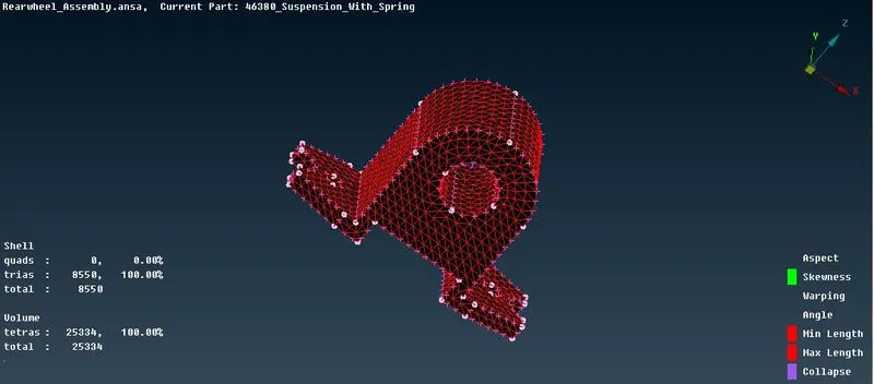
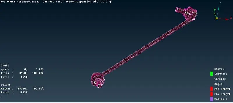
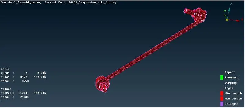
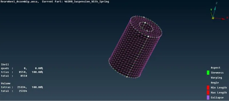
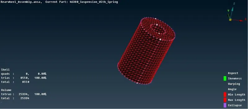
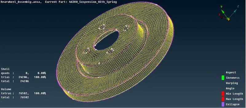
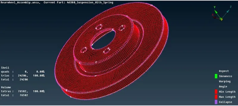
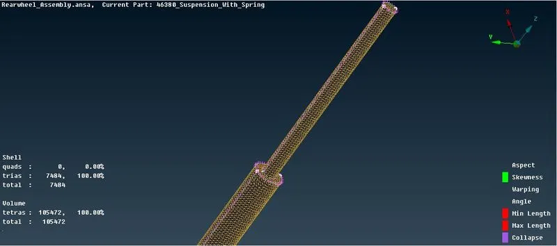
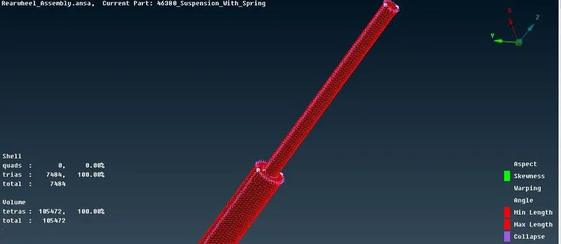
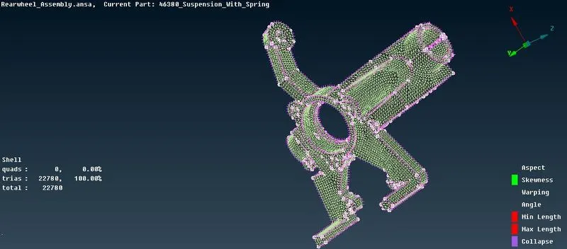
- Now the volume mesh is done we will go for the non uniform surface meshing for that we will use spot mesh or batch mesh accordingly and after the surface meshing is done we will perform solid/volume meshing on those component.
- So all the component with surface and volume meshing done are shown below:
1.
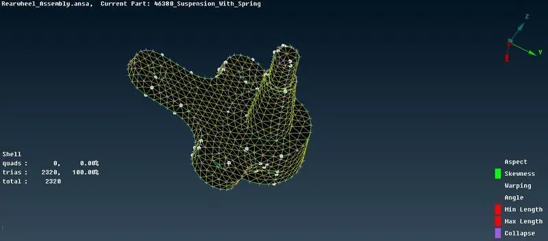
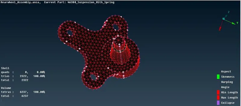
2.
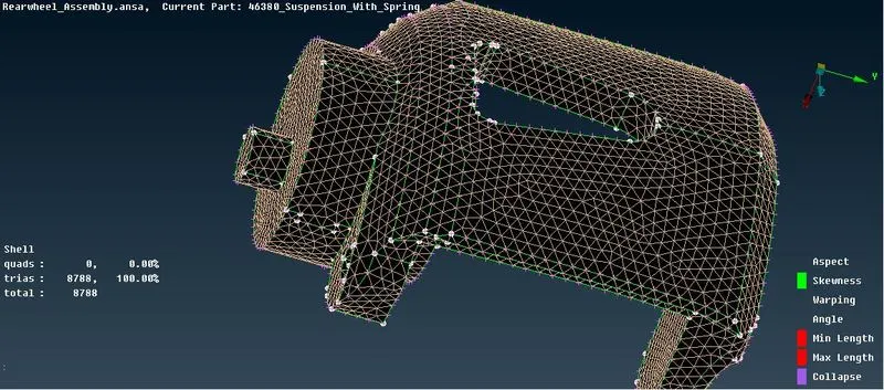
3.
4.
5.
6.
7.
8.
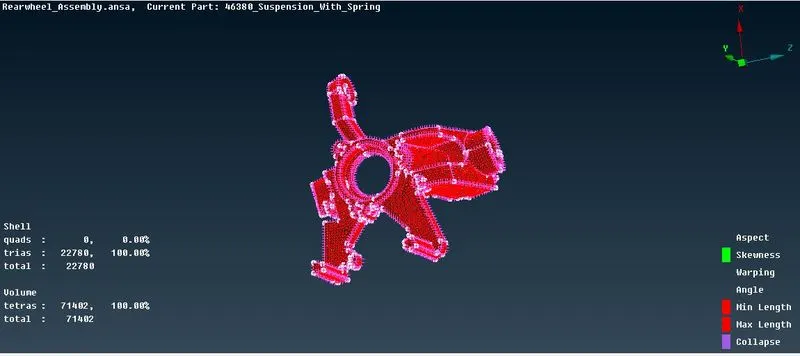
9.
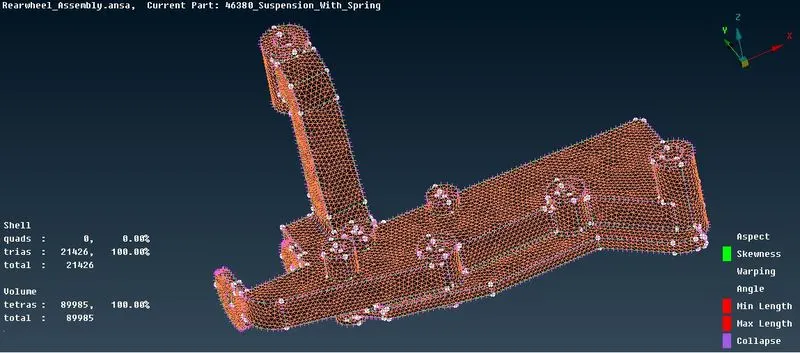
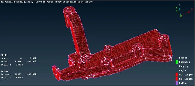
- So this is how surface meshing and volume meshing is done.
- No the one part is remaining and that is spring. Now is this we will represent the spring as a 1D bar elements.
- For this first generate the middle of the spring using CURVES>MIDDLE from TOPPO module
- And then connect the curves into single curve usning CURVES>CONNECT>MULTI as shown below:
Middle:
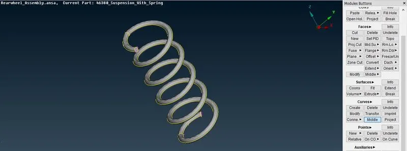
Connected:
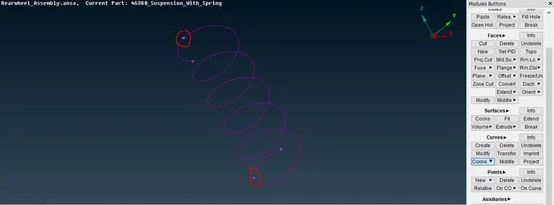
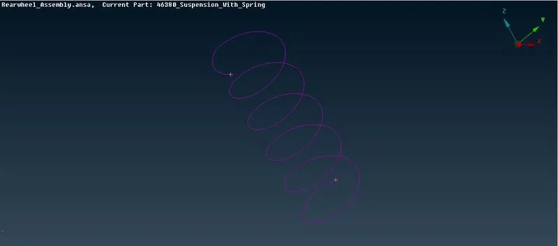
- Now next is create the COG of the curve using CURVES>COG
- Then go to the NASTRAN module and select the ELEMENTS>CBAR
COG:
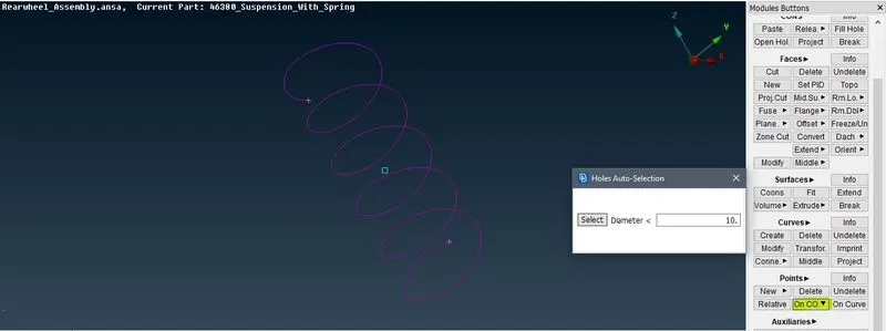
CBAR:
- Now in CBAR change the selection type of the curve box and after that select CURVE and COG as Orientation and then assign the length as shown:
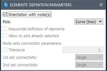
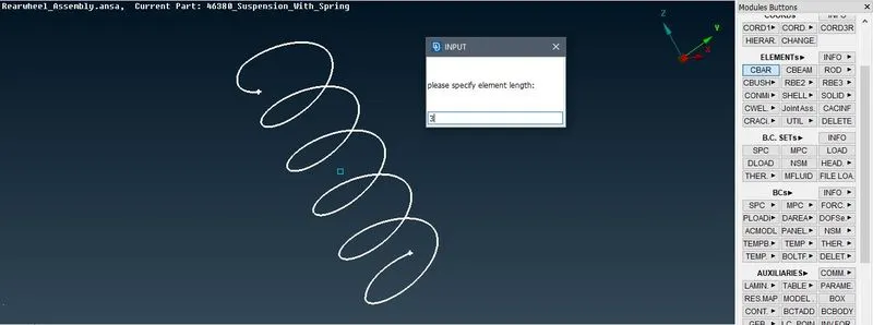
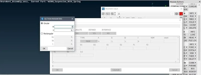
- Now after specifying the value next is to create new PID for the spring, after creating the new PID press SHIFT+? be selecting the box A and assign the radius in the box and the PID is created as shown:
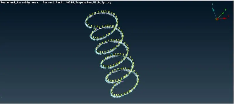
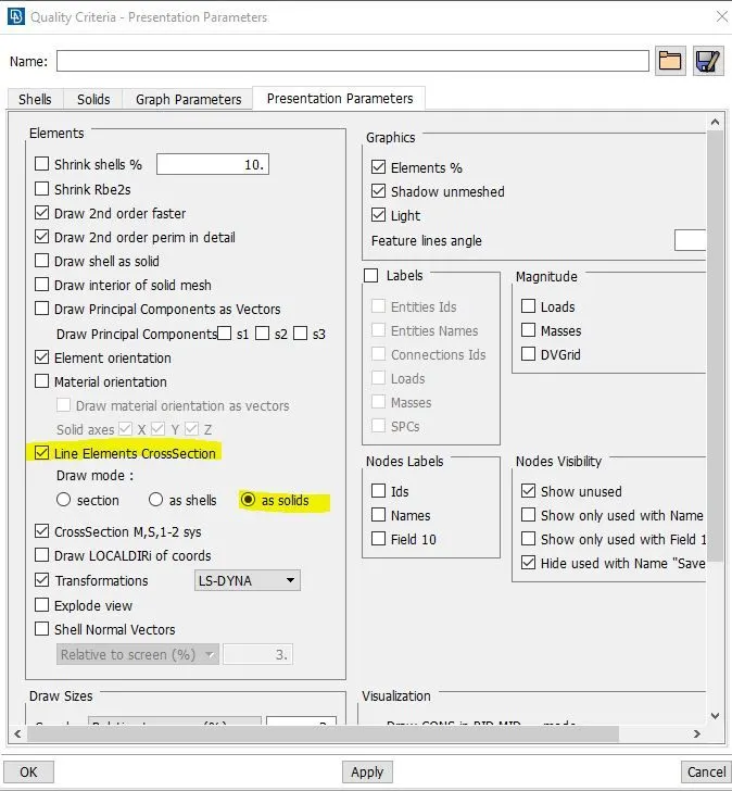
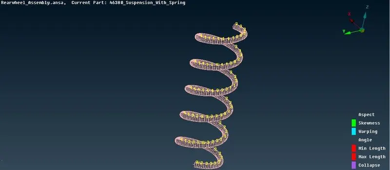
- Now to reperesnt the actual curve go to the Quality criteria then Parameters Presentations and check on the following box as shown:
- The cruve will look like this:
- Now next is CONNECTION PART , for connection we will be doing Rigid connection for that we have to to the NASTRAN module for performing the connection operation.
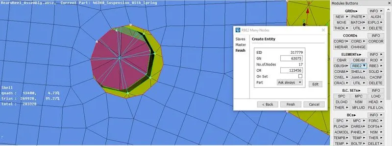
- First we will perform the RBE2 multi nodes connection for that go the ELEMENTS>RBE2>MULTI and select the nodes as shown:
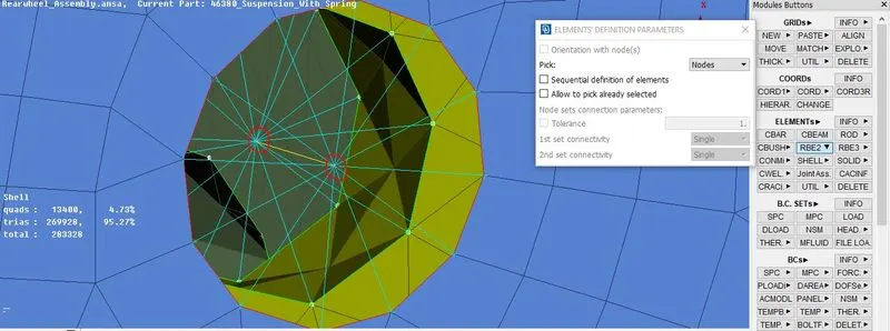
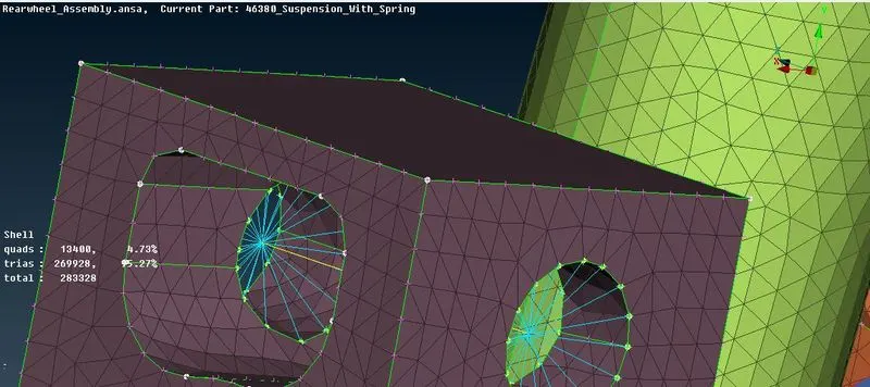
- Now we whave to connect those two RBE2 connection two each other for that we will use the Two nodes connection for that go to the ELEMENTS>RBE2>TWO NODES , then select the two nodes which you have to connect and perform the operation as shown.
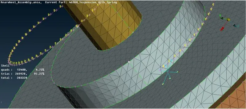
- Now we will go for seam welding for that we have to create a curve on the welding con. For that we will use the CURVE>CONS2CURVE operartion from TOPPO module
- After creating curve select the CONVERT option from ASSEMBLY area and chose the CURVE option in that choose the CURVE to be converted and then select the SEAM WELD as shown:
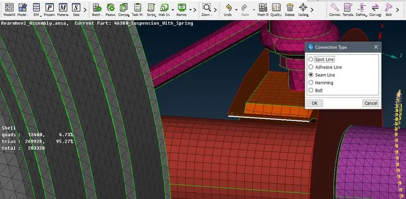
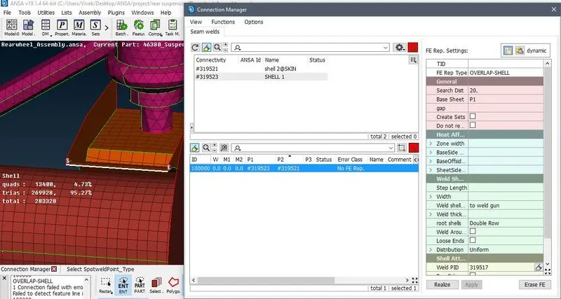
- After that we have to perfrom connection fro that go to the CONNECTION MANAGER and select seam weld line, after selecting the weld line and add the P1 and P2.
- So the surfaces are paraller thats why we have to select OVERLAPSHELL shown as follow:
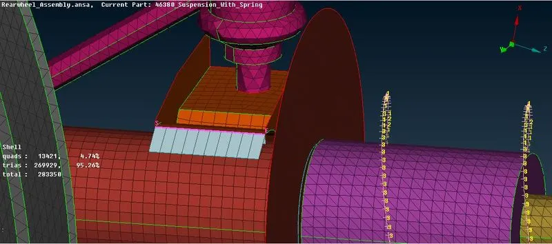
- Now after applying and clicked on Realize and the weld is appeared as shown :
- Now the all midsurfacing, meshing and connection is done we have to perform the symmetry operation.
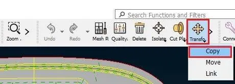
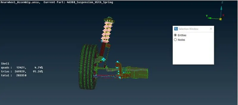
- For that go TRANSFORM>COPY>ENTITIES form UTILITIES module and then selct the entire copmponent (entity) as shown:
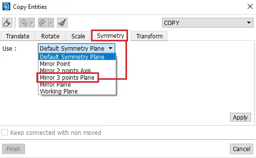
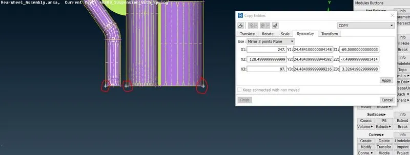
- After that go the SYMMETRY OPERATION and select the MIRROR 3 POINTS PLANE and then select the points as shown then click on APPLY and you symmetry operation is done as shown:
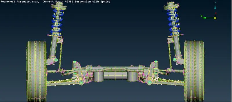
- And this is how the actual component will look like :
LEARNING OUTCOMES:
- Assigned proper PIDs to each component.
- Able to generate mid surface and volume mesh.
- Able to perfrom the connection properly.
- Aware of the quality criterias and mesh parameters
- Got used to with batch meshing
- Able to perform symmetry operation.
CONCLUSION:
The component of rear suspension system are captured with solid elements(tetra) and shell elements. The volume mesh is generated properly where required.All the area are captured with the tria element. And appropriate bolt and welding connection are give to the coponent.