Project - 2 - Meshing on the suspension Assembly
AIM:
- Mesh the given rear suspension assembly accordingly with 2D & Volume meshing as per the given quality criteria. Connections to be deployed for the model. Replicate the model symmetrically after all the meshing and connections.
OBJECTIVE:
- For the given assembly,check for the geometrical errors
- mesh with the given element Quality criteria. After meshing assign the component thickness to mid surfaces.
- Use tetra elements to model non-uniform thickness components.
- use Appropriate connections to connect the component
- perform Symmetry command to reflect the half finished model to the other side.
QUALITY CRITERIA:
- Quality Criteria for Surface Meshing of Tyre and Rim (Element type: Tria) :
S.No
Quality Criteria
Value
1
Target/Average length
6.5
2
Minimum Length
5
3
Maximum Length
10
4
Skewness
45
Quality criteria for Surface Meshing of Non Uniform thickness components other than Tyre and Rim (Element type: Tria) :
S.No
Quality Criteria
Value
1
Target/Average length
4
2
Minimum Length
2
3
Maximum Length
6
4
Skewness
45
Quality Criteria for Volume meshing of all Non Uniform thickness components (Element type: Tetra Elements):
S.No
Quality Criteria
Value
1
Tet-collapse
0.2
Quality criteria for Mid surfacing of Uniform thickness part which has thickness less than 5 mm (Element type: Mixed elements) :
S.No
Quality Criteria
Value
1
Target/Average length
4
2
Minimum Length
2
3
Maximum Length
6
4
Aspect
3
5
Warpage
15
6
Skewness
45
7
Jacobian
0.7
8
Minimum Quad Angle
45
9
Maximum Quad Angle
135
10
Minimum Tria Angle
30
11
Maximum Tria Angle
120
THEORY:
-
Modern suspensions are composed of hundreds of different parts, and vehicles vary tremendously in their suspension designs, but every suspension is composed of certain basic parts which are common in all, some of which are shown below.
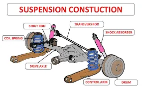
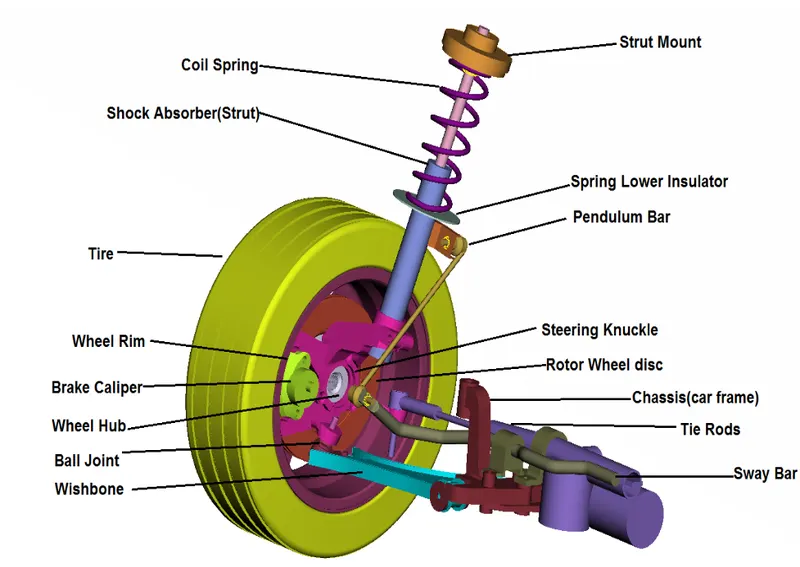
The basic components of a suspension system are as follows:
- CONTROL ARM(a movable lever that fastens the steering knuckle to the vehicle frame or body).
- CONTROL ARM BUSHING(a sleeve, which allows the control arm to move up and down on the frame).
- STRUT ROD(prevents the control arm from swinging to the front or rear of the vehicle).
- BALL JOINTS(a swivel joint that allows the control arm and steering knuckle to move up and down, as well as side to side).
- SHOCK ABSORBER or STRUT(keeps the suspension from continuing to bounce after spring compression and extension).
- STABILIZER BAR(limits body roll of the vehicle during cornering).
- SPRING (supports the weight of the vehicle; permits the control arm and wheel to move up and down).
PROCEDURE:
- Import the assembly model,as shown in below.
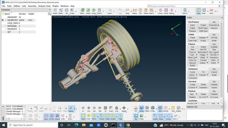 .
.
- With geometry checks ,Topological errors and proper oreintation,as shown in below.
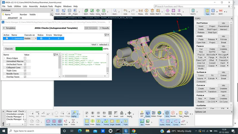 .
.
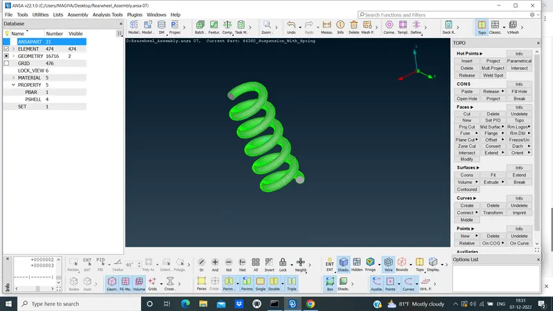
- Set the separate PID of spring fro the assembly and to convert the 1D bar element,as shown in below.
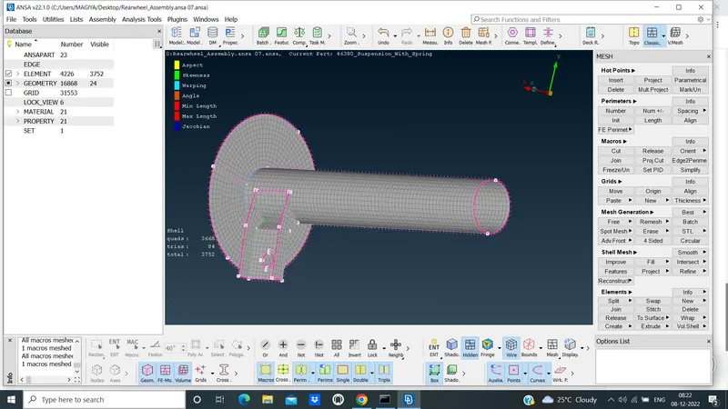
- Extract the Mid surface and meshing the 2D shells as per given quality criteria,as shown in below.
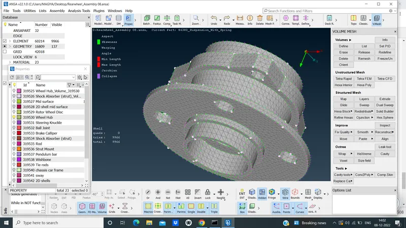
- Surface meshing for the wheel hub,as shown in figure.
- The other component of suspension assembly can do surface meshing similarly.
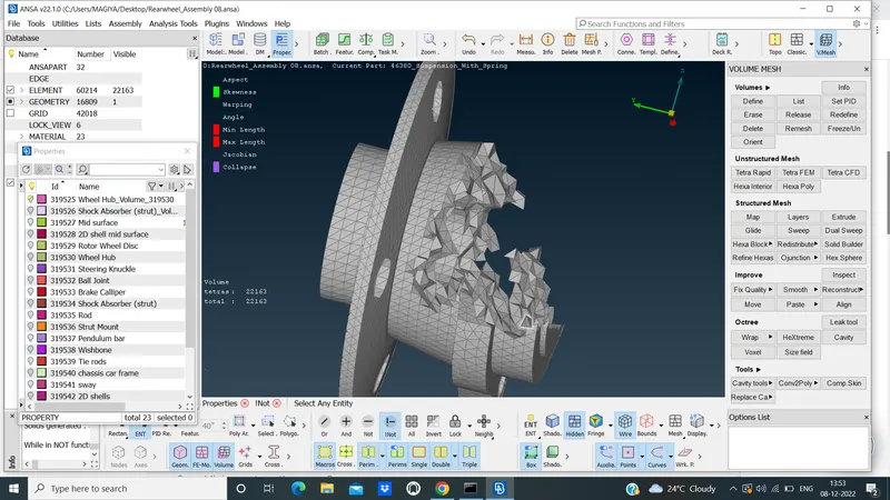
- Volume meshing for the wheel hub,as shown in figure.
- The other components of suspension assembly can do volume meshing similarly.
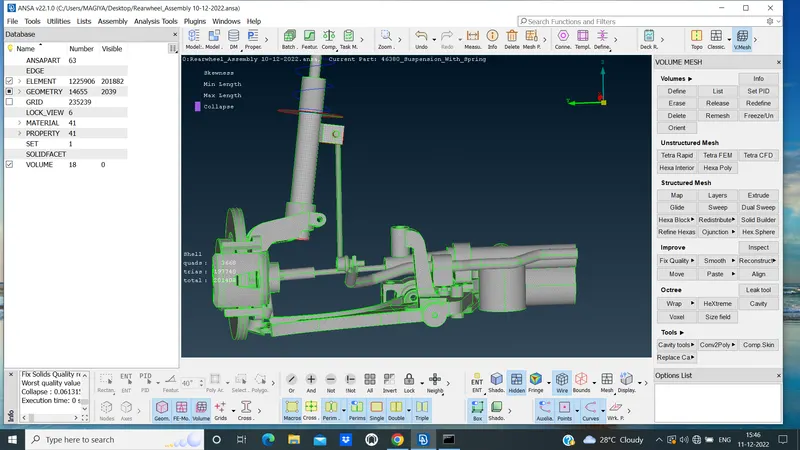
- The all solid components by surface meshing as per given quality criteria,as shown in below.
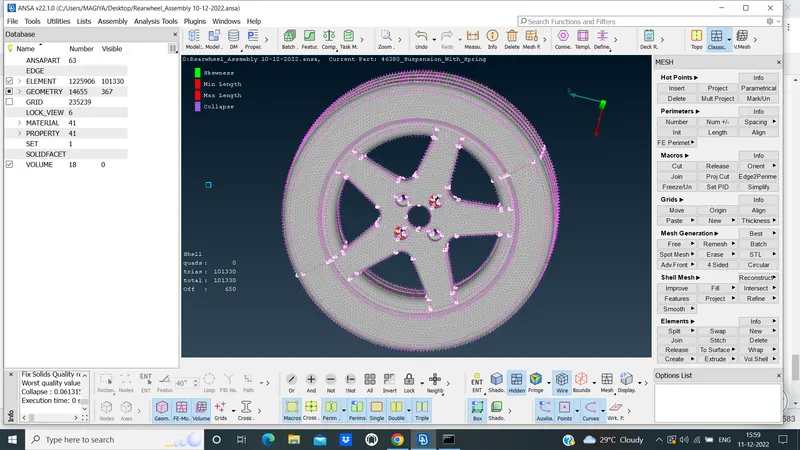
- The Trye and Rim component of surface meshing,as shown in below.
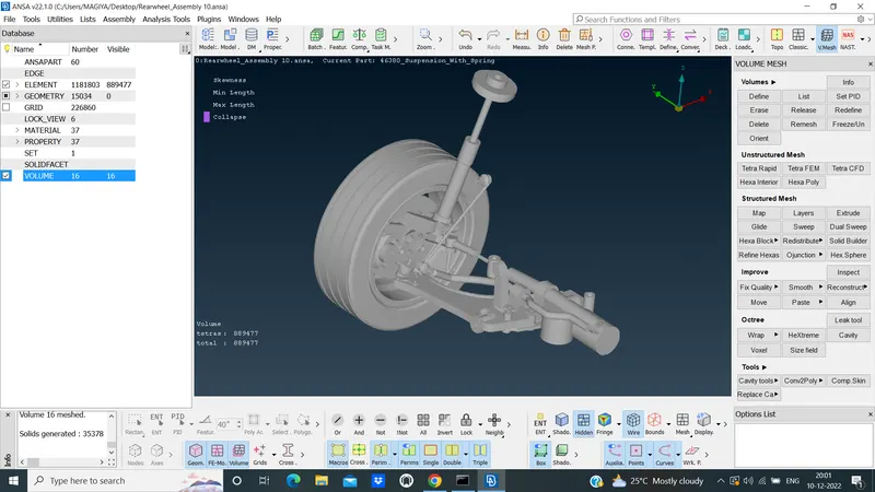
- The all solid components including the Tyre and Rim by volume meshing,as shown in below.
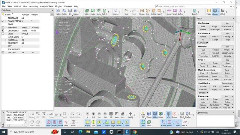
- Making the connection where it required the seam weld,RBE 2,C bush and spot weld,as shown in below.
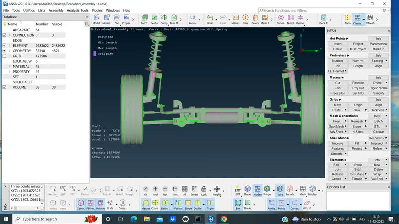
- Using Transform copy option by 3 Mirror plane and transforms it,as shown in below.
 .
.
LEARNING OUTCOMES:
- Learned how to do geometry check by using check geometry option in tools.
- Learned how to give new PIDs.
- Learned how to do topological clean up by using options like cut and new in faces.
- Learned how to apply quality criteria and mesh parameters to any model.
- Learned how to do meshing both mixed and tria by using spot mesh in mesh module.
- Learned how to improve the mesh by using reconstruct and smooth option in mesh module.
- Learned how to do volume meshing by using tetra elements.
- Learned how to define a volume to any part in any model.
- Learned how to do mid surfacing by using offset
- Learned how to assigne thickness to the mid surface.
- Learned how to do connections like RBE2 and seam weld connections.
- Learned how to do PBAR connection.
- Learned how to reflect the model by using symmetry option.
CONCLUSION:
- Finally,Meshing on the give suspension assembly according to the given quality criteria and mesh parameters.Use Appropriate connections to connect the suspension assembly and perform Symmetry command to reflect the half finished model to the other side is done.