Project - 2 - Meshing on the suspension Assembly
Aim: to mesh the given model of rear wheel suspension.
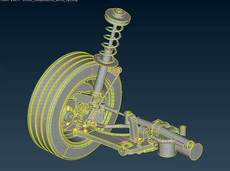
Objective:
- Check for geometrical errors
- Generate mesh for the outer surface of the parts that have variable thickness above 5 mm
- Generate the midsurface of parts that have thickness of 5 mm or less
- Generate the solid mesh and 2D mesh of midsurfaces
- Maintain the given mesh element quality criteria
- Provide necessary connections between parts
Geometry clean-up is done using the Checks > Geometry option, where a list of all the geometry failures is given. The failures can be addressed manually or the Fix option can be called to eliminate the issues automatically.
For outer surface mesh, tria and ortho-tria was used for plane and curve surfaces respectively. Wherever the quality was failing, the Reconstruct option was used. If it was not enough then Move command was used to tweak the position of nodes until the elements fell under the desired quality criteria.
Once the surface mesh was created, the volumes were defined and meshed using Tetra Rapid algorithm.
Side by side, the midsurfaces were meshed using mixed elements.
After the parts were done meshing and connecting, the whole model was copied along its symmetrical plane. This made the assembly complete.
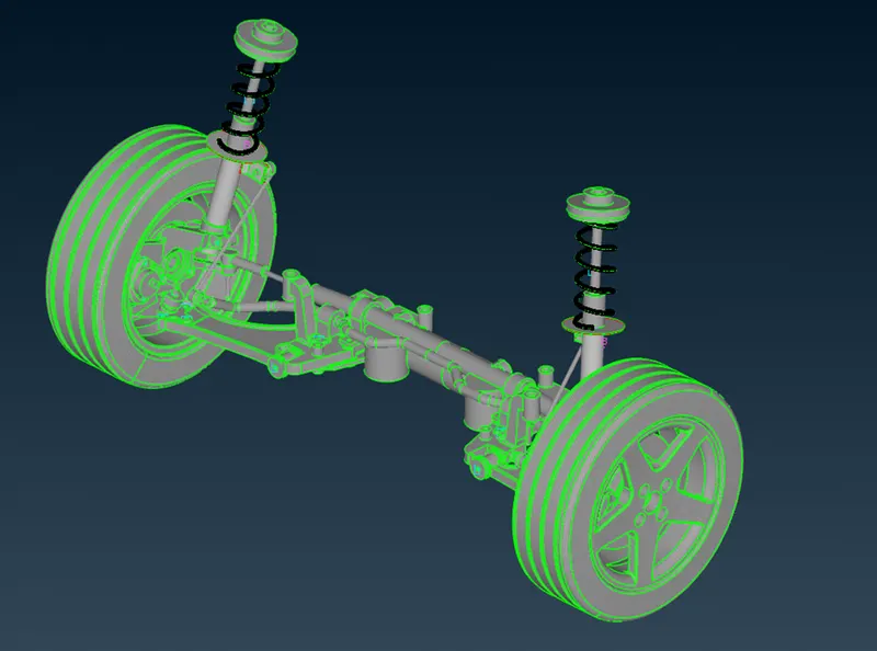
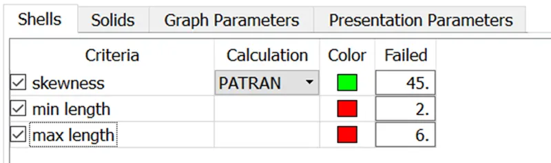
Figure 1 for other parts.
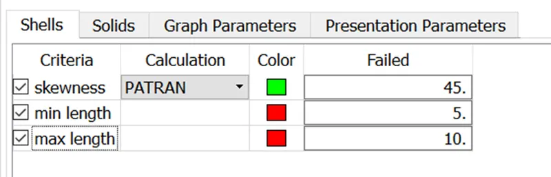
Figure 2 for tyre and rim
The tet collapse was set to 0.2 for all parts.
Connections:
- RBE2 > Many nodes/Two nodes were used in all the cases of bolt connections.
- Overlap shell joint was used for weldments.
- For spring CBAR 1D elements were used to show the connection.
Conclusion: This exercise gave me insight about the actual industry practice.
File link: https://drive.google.com/file/d/11Pduz29DuCbhruD3obdk6fhnDsqENaJn/view?usp=sharing