Photo Realistic Rendering
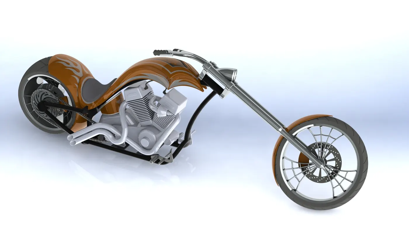
Assembly of Chopper Model
Objective: To create individual parts and assembly of the same of an American Chopper.
in this course, Ultimate Solidworks, I had to create a model of an American Chopper. To do that I had to build each part individually with proper dimensions, apply proper and appropriate appearance to them and assembled them with proper mates and relations. To complete the aforementioned tasks, I had to learn new features and functions of Solidworks. And I will be discussing about them along with the procedure of modelling next.
The methodology or sequence I followed is
- transmission belt
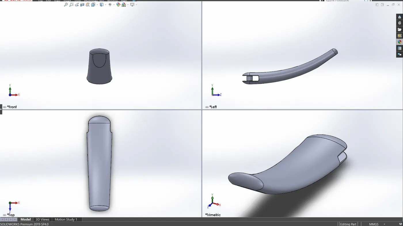
- kickstand
- front fender
- rear fender
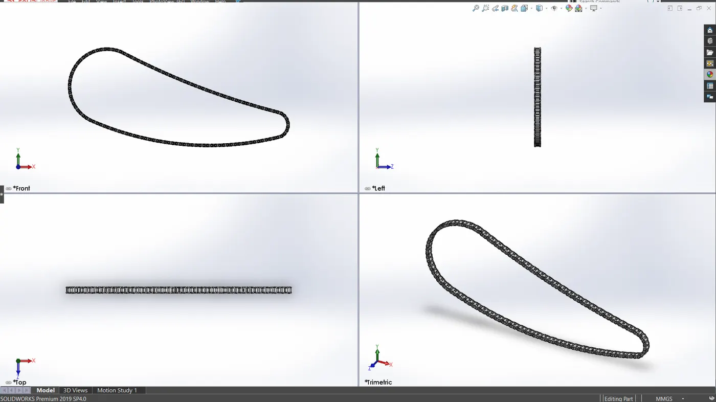
- chain
- oil tank
- pedal
- front wheel
- rear wheel
- front fork
- chassis
- engine
- gas tank
The features or tools that I used to make the parts are:
- Sketch- it is a simple drawing of the part drawn on a 2d view. It forms the base of any modelling as it contains the greatest number of dimensions. To form a sketch a lot of tools and entities are available which are basically 2d shapes like line, circle, arc, polygon, spline, etc. and functions like trim, mirror, pattern, extend, smart dimension etc. These functions make the drawing or sketching easy and accurate.
- Extrude Boss/Bass- This function converts the 2d sketches into 3d models. It actually extends a closed boundary profile in a direction perpendicular to the plane of sketch. There are other options of choosing the start and end positions of the extension which makes it quite handy.
- Revolve-This tool makes a 3d object out of a closed profile by rotating it about a fixed axis. The axis generally is a part of the same sketch.
- Extrude Cut- it is the same as extrude. The only difference being is that it removes material instead of adding any.
- Revolve cut: just like extrude cut it also removes material in the same method and direction as the Revolve function.
- Fillet: this tool is used to give the sharp corners a smooth rounded look. One can change the radius both symmetrically and asymmetrically.
- Chamfer: it is like inserting a third face between two other faces that are at an angle and share the same edge. This third face takes the place of the common edge and gives rise to two new edges.
- Lofted Base/Base: this feature allows you to create a complex structure whose cross-section(s) follow(s) a specific path. We can set more than two profiles as cross-section. This same feature can be used to add or remove material.
- Dome: as the name suggests this feature adds dome to faces irrespective of being planar or non-planar. Even irregular shaped faces can be used to make this feature.
- Combine: it adds more than one solid bodies and converts them into one solid body.
- Shell: it creates a hollow compartment inside any solid body leaving a set thickness.
- Offset: multiple sketch entities can be shifted to both their sides by a specified amount.
- Trim Entities: it erases the part of sketch entities that overhangs beyond other entities or is in between other two entities.
- Split: this command can divide one or several bodies into separate parts. The division is governed by other sketch or or plane or surface.
- Dynamic Mirror: this mirrors the sketch entities that are drawn about a selected line in real time.
- Circular Pattern: it creates copies of a feature, body, sketch entities or even parts in an assembly in a circular path with specified number of instances and spacing.
- Linear Pattern: it creates copies of features, bodies, sketch entities or parts in a linear path (it can be in two axes as well) with specified number of instances and spacing.
- Appearances: with this tool the colour of a feature, face, body or part can be changed with the preloaded appearances in the library.
- Lofted Surface: it creates a 3D surface by using multiple closed profile. Tangency is applied between the profiles by default.
- Swept Surfaces: it uses multiple profiles placed along a certain path to create curved surfaces.
- Filled Surface: it creates a surface between any number of sides. It uses edges, lines, curves as boundaries.
- Surface Trim: it is used to cut away surface by making another surface as a reference.
- Knit Surface: it is used to make more than one surfaces with adjacent or overlapping edges to come closer and make them suitable for creating a solid body.
Transmission Belt
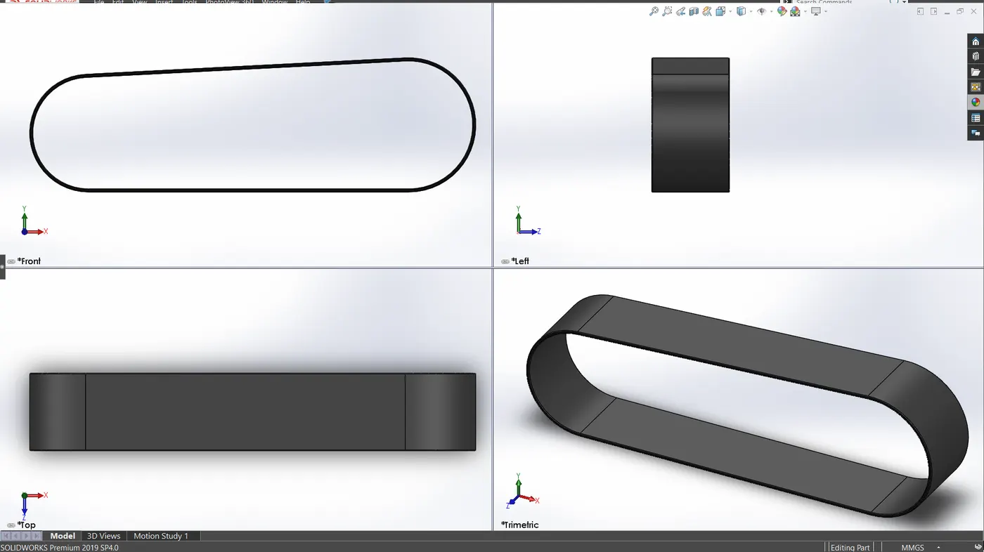
Kickstand
Chain
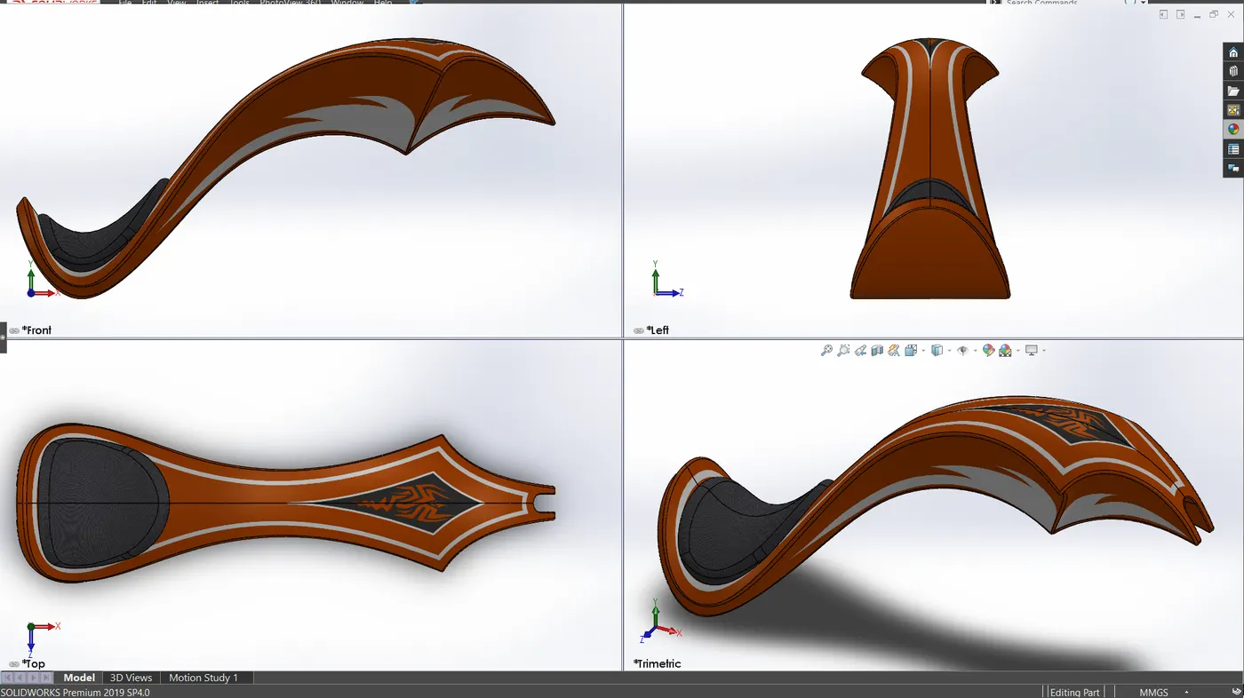
Front Fender
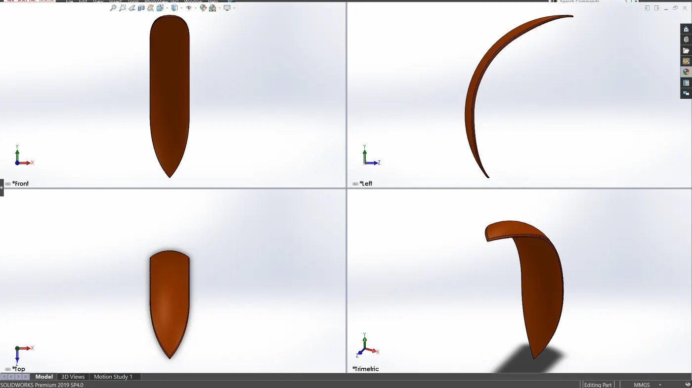
Rear Fender
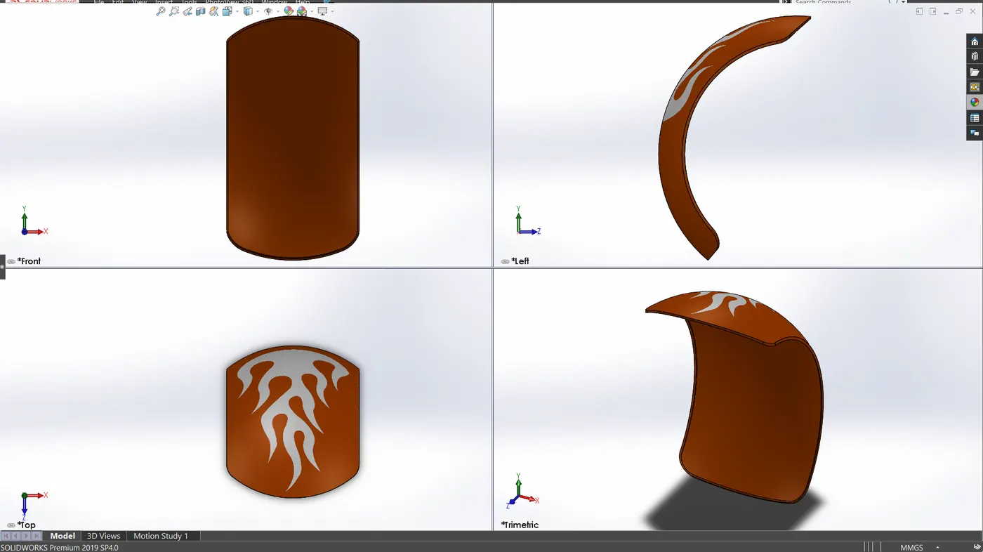
Oil Tank
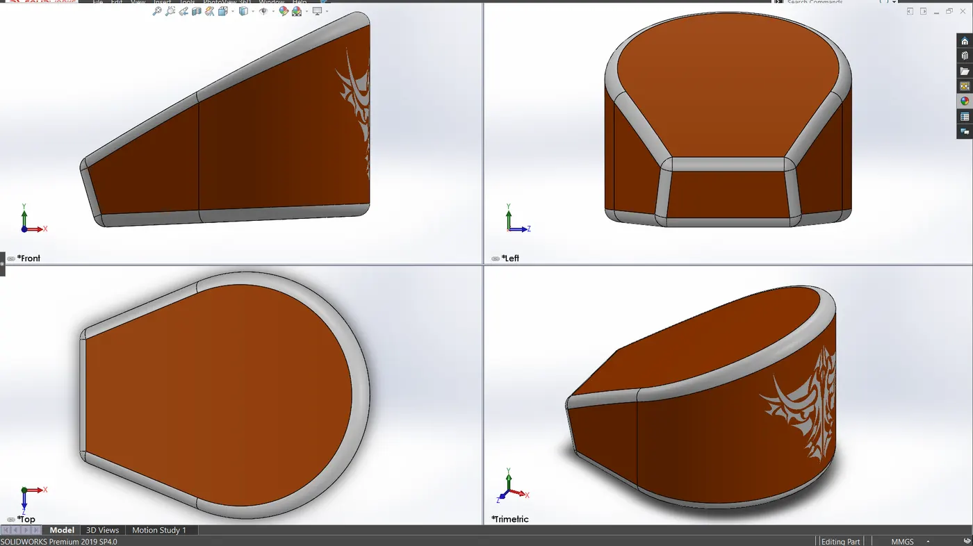
Pedal
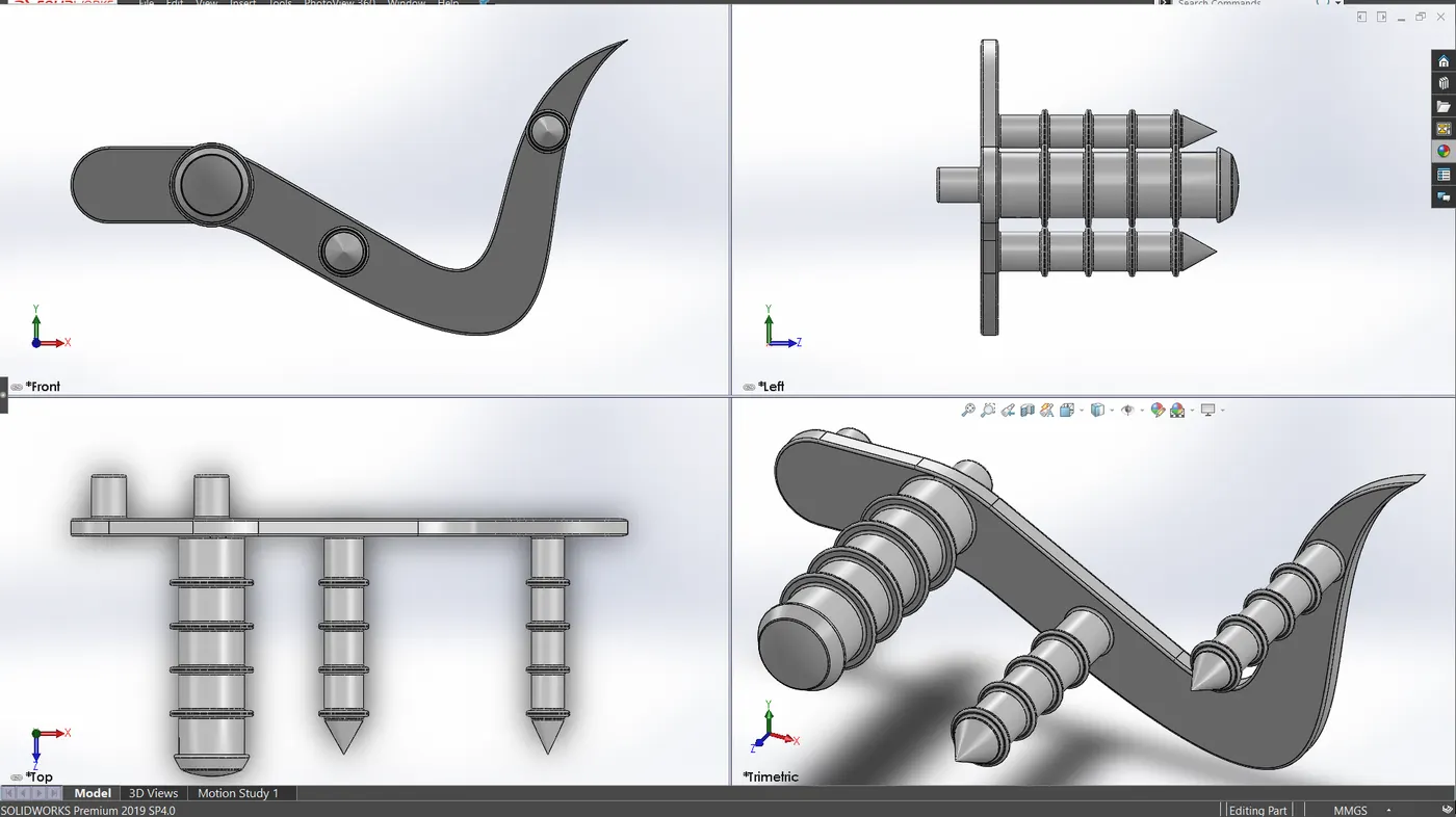
Front Wheel
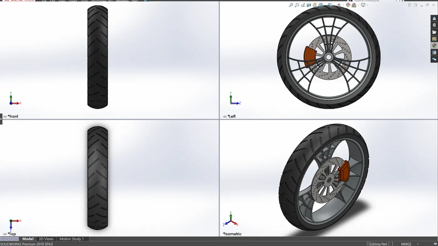
Rear Wheel
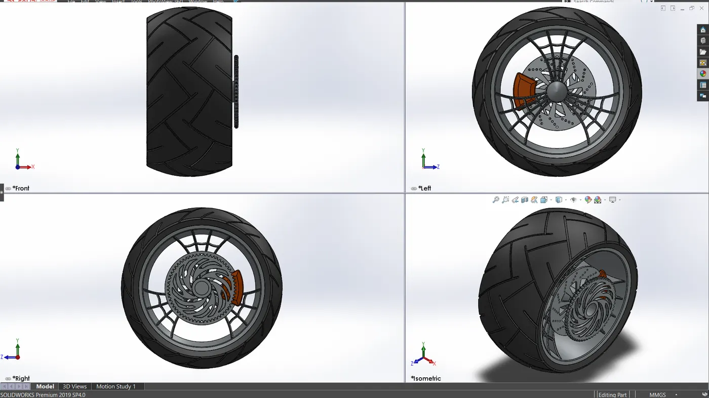
Front Fork
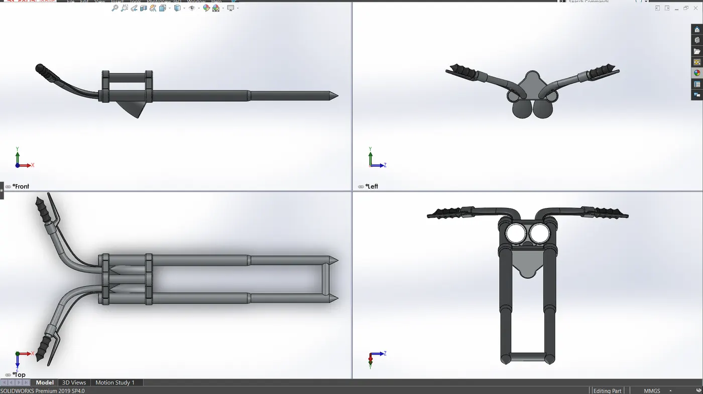
Chassis
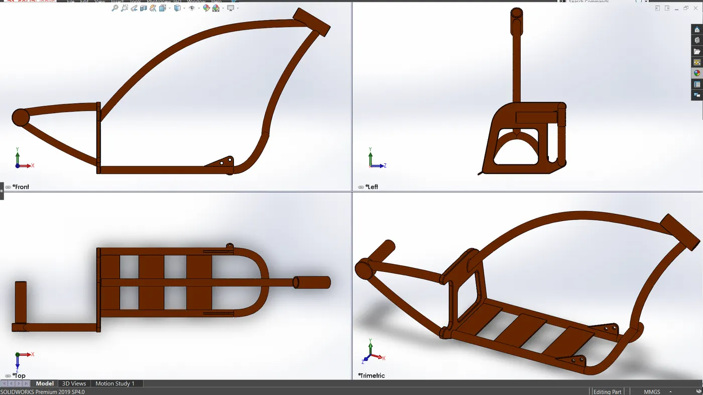
Engine
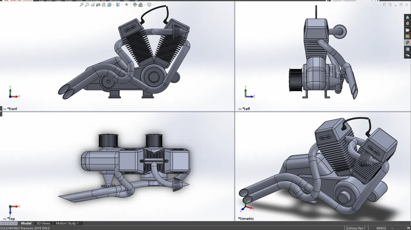
Gas Tank
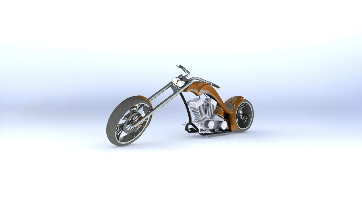
American Chopper Assembly
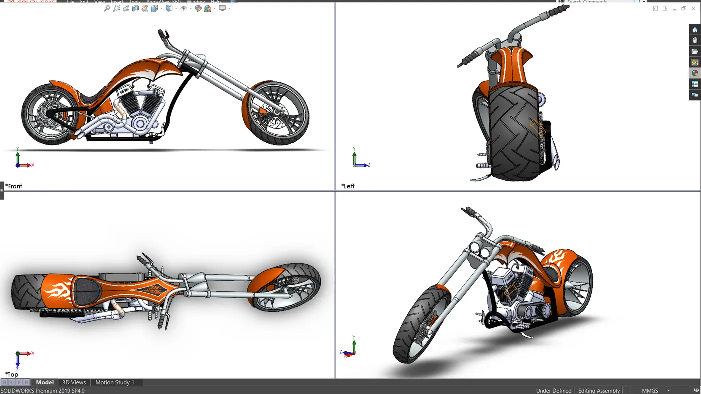
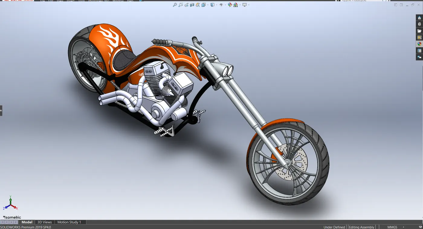
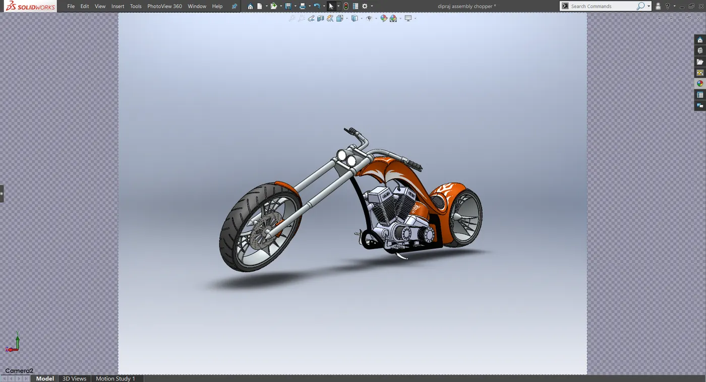
Rendered Images of the Assembly Model
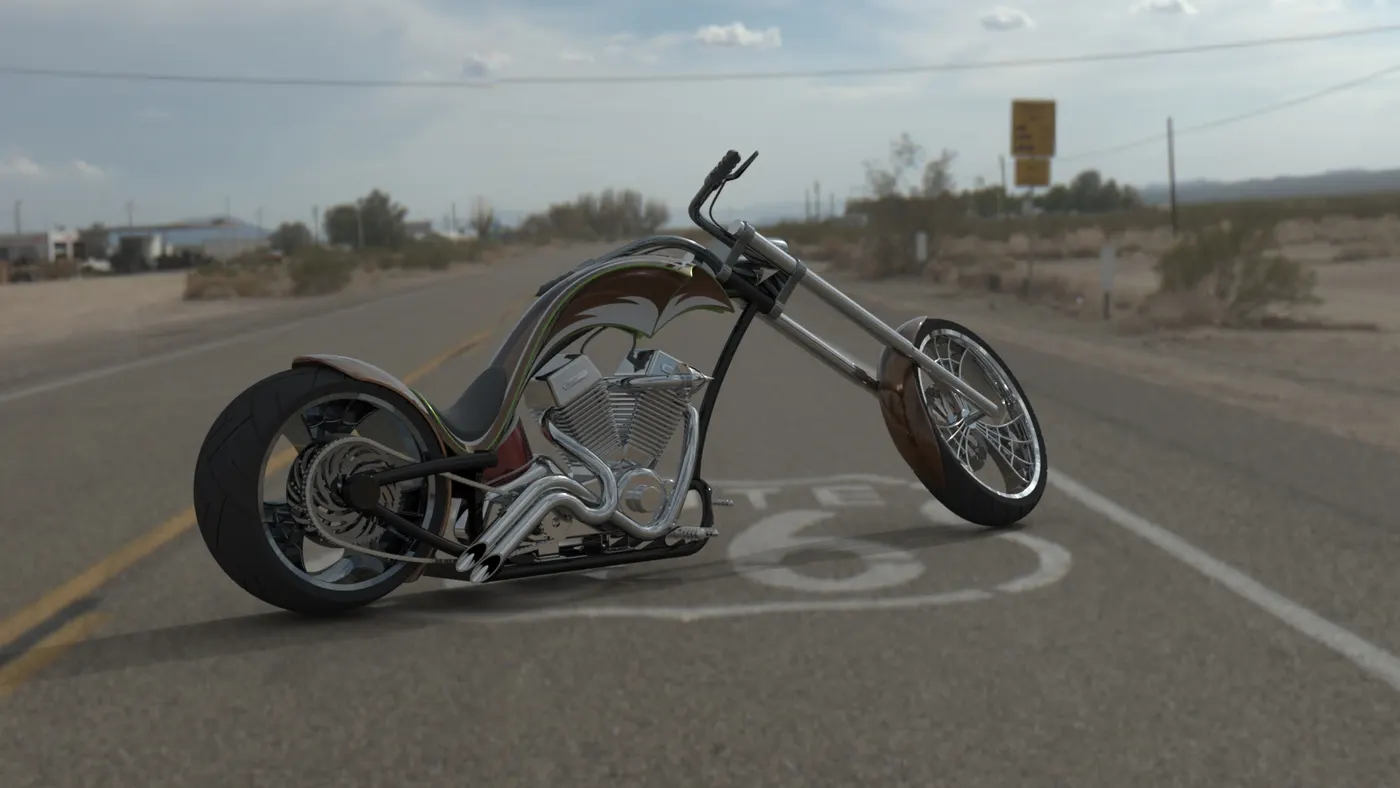
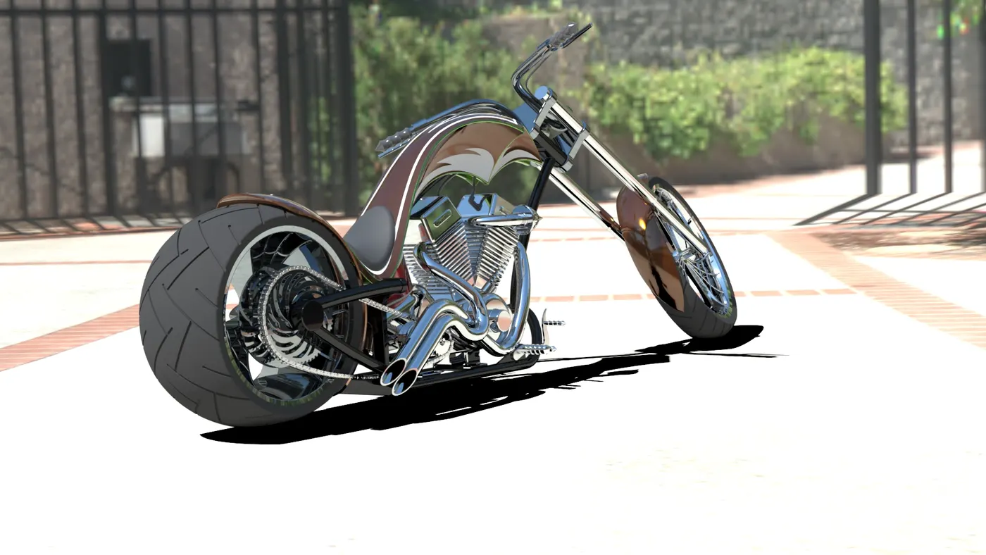
I have rendered the model in Photoview 360 and Solidworks Visualize.
Route 66
Driveway
Conclusion
After completing the course upto here, I can now succesfully design an assembly model of American Chopper in Solidworks and render its photo-realistic images through Photoview 360 and Solidworks Visualize. in this course Sir Saunder Rajan has helped me a lot to overcome any difficulties.