Project - 2 - Meshing on the suspension Assembly
Aim:
To do Volume Tetra meshing on the given rear suspension Assembly
Procedure:
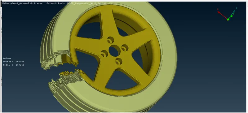
1)Import the geometry of given CAD geometry which consists of Tire,Rim and other child parts.
2)Do the geometry clean up through check manager-geometry and ensure it is free from Topo errors
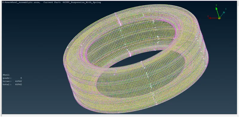
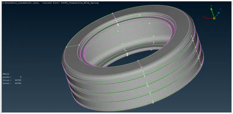
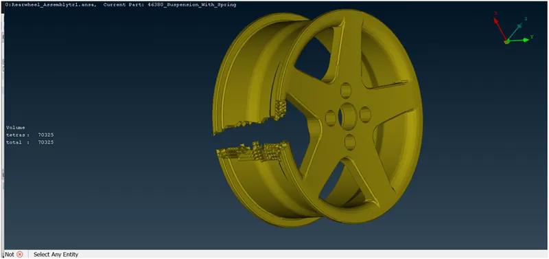
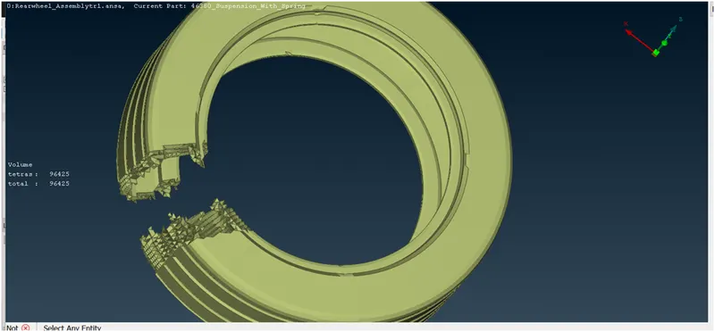
3)The Rim and Tire are meshed with Ortho tetra meshing by spot meshing method
4)The rim and Tire are then solid meshed through unstructured method by Tetra rapid algorithm
Quality Criteria for Surface Meshing of Tyre and Rim (Element type: Tria) :
|
S.No |
Quality Criteria |
Value |
|
1 |
Target/Average length |
6.5 |
|
2 |
Minimum Length |
5 |
|
3 |
Maximum Length |
10 |
|
4 |
Skewness |
45 |
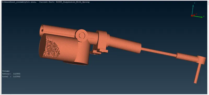
Above Fig: solid meshed Tie Rod
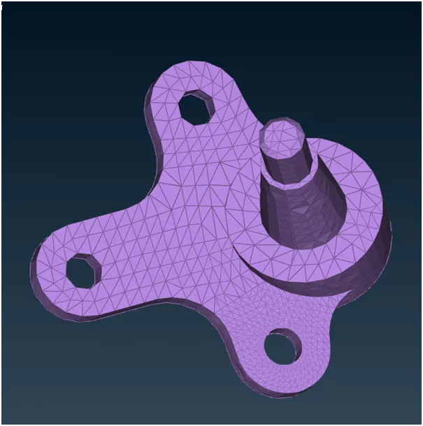
Above fig: Ball Joint
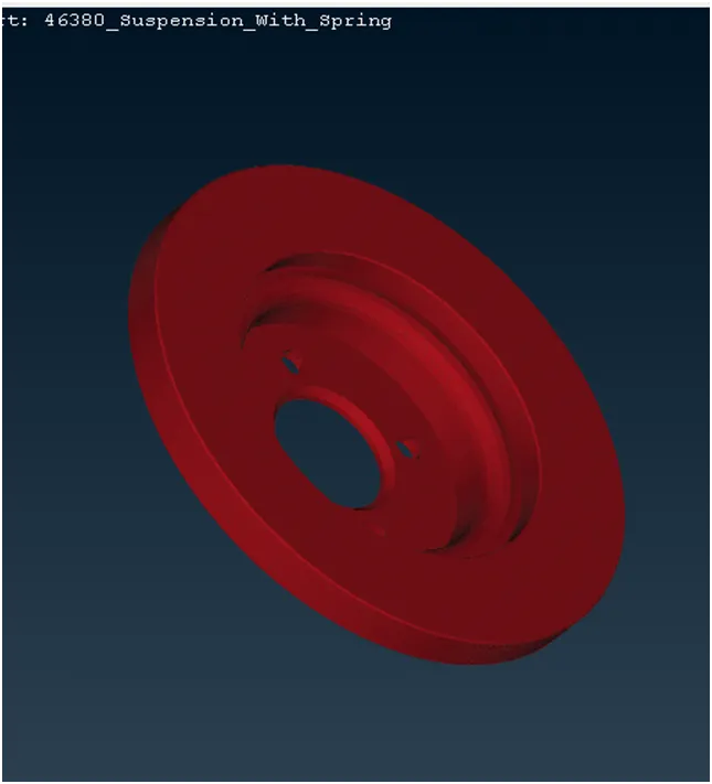
Above Fig:Rotor wheel disc
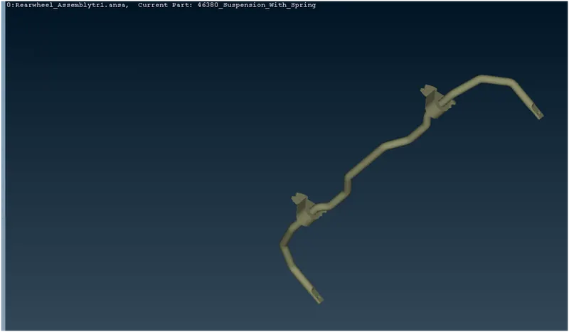
Above Fig:Sway Bar
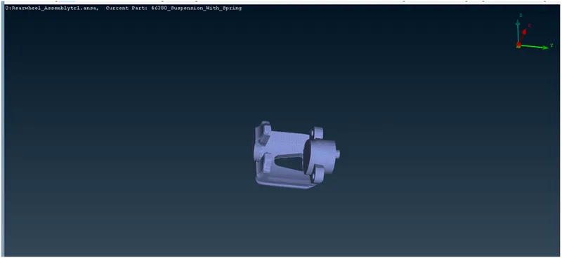
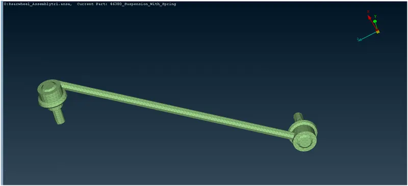
Above Fig:Pendulum bar
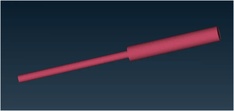
Above Fig:Shock Absorber
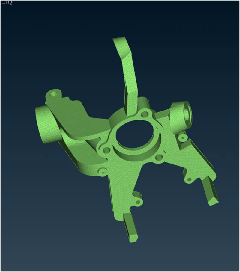
Above Fig:Knuckle streeing joint
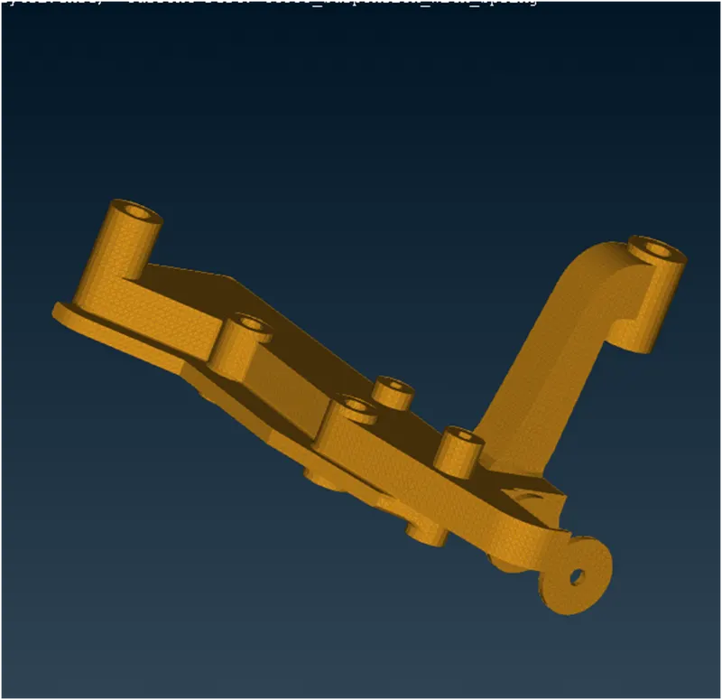
Above Fig:Chasis car frame
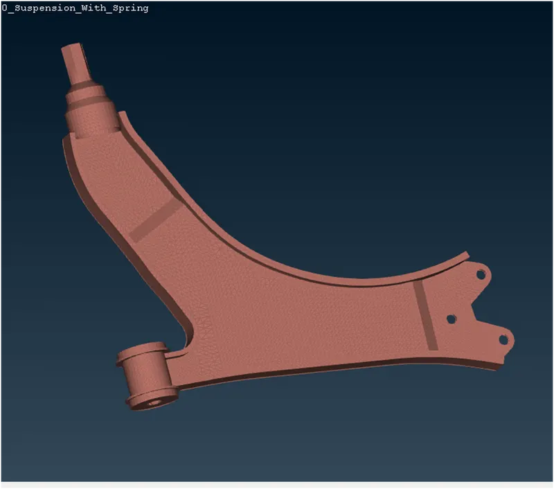
Above Fig:Control Arm WB
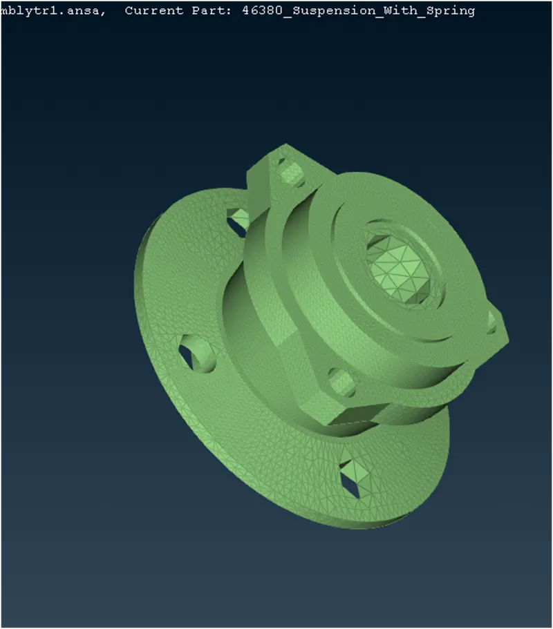
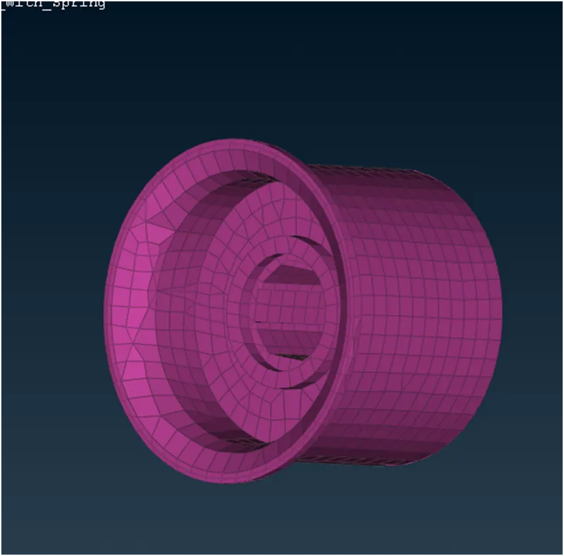
Above Fig:Bush
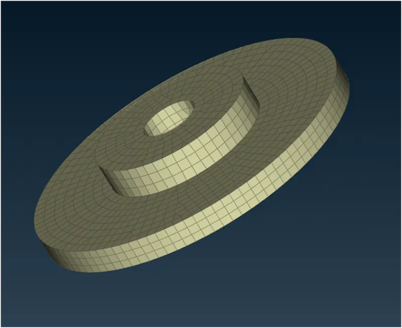
Above Fig:Top Sturt
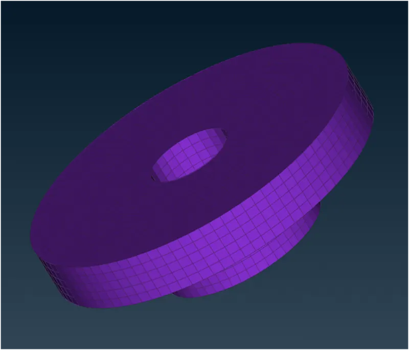
Above Fig:Bottom Sturt
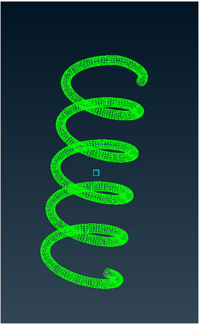
Spring -1D solid meshed
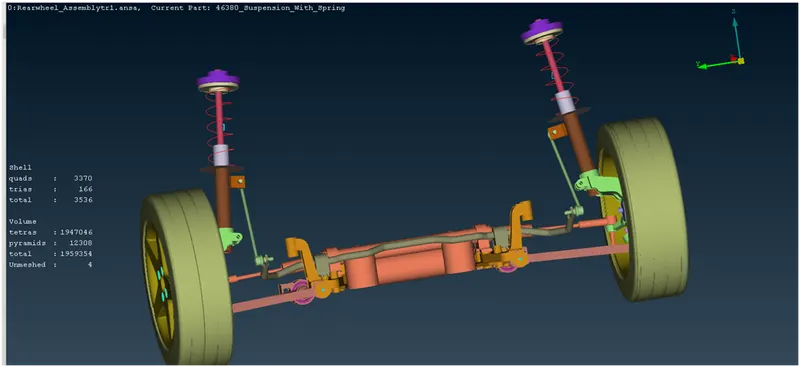
Above fig:Full rear wheel suspension Assembly
LEARNING OUTCOMES
- Through this project, Things learnt are tetra-meshing and connection deployment processes.
- Learnt to use 1D CBAR elements to represent spring components.
- Learnt more about various parts involved in a standard suspension assembly.
RESULT
The given suspension assembly was checked for geometrical errors and fixed accordingly. In addition to that, it was meshed in both 2D and 3D as per the given quality criteria and parameters. Connections were deployed and finally, a symmetrical half was created and reflected to complete the other side of the assembly
solid meshed File is attached as Zip format