Project - 2 - Meshing on the suspension Assembly
Aim-
For the given assembly, check for the geometrical errors and mesh with the given element Quality criteria. After meshing the component the thickness has to be assigned for mid surfaces. Use tetra elements to model non-uniform thickness components. Also use Appropriate connections to connect the component.At last perform Symmetry command to reflect the half finished model to the other side.
Procedure-
1.Import the given model in ANSA and check for geometrical errors, resolve if any.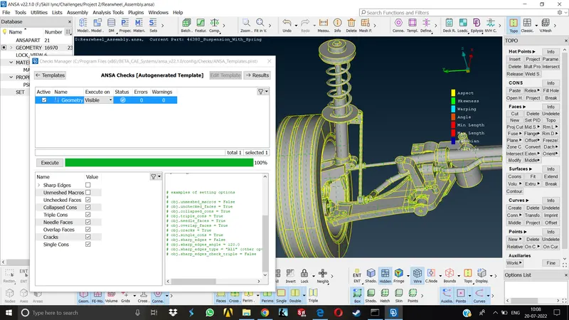
2.As this model contains a lot of different components as it is a front subframe with wheels & suspension assembly,we have to first separate them and assign unique PIDs for all the components.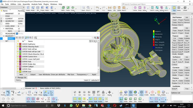
3.The major components of this assembly contains Front Subframe, Steering rack with Tie rods, Lower control arm with ball joints, Anti roll bar with its bushings and mountings,Tyres & Rim(Wheel), Main Hub or Knuckle which holds the front main strut, Brake caliper and disc, Tie rod & lower control arm together.
4.Once all the components are assigned proper PIDs, we can now proceed with Midsurfacing and Meshing them one by one according to given quality criteria.
Meshing the tyre & rim-
1.As this is a non-uniform thickness component with avg thickness > 5mm , we have to create a surface mesh first and then create a volume mesh ( Tetra mesh ) as per given QC.
2.Firstly, As the target element length is 6.5 mm, we have to change the length of perimeters & macros to the speciifed target length.
3.There are a lot of feature lines that will be failing for min. element length. Here, batch mesh tool will save a lot of time and will give us desired results with min. time requirement.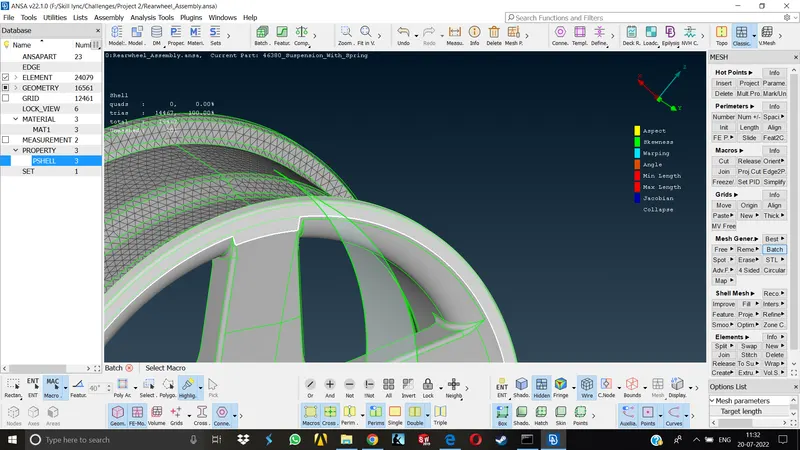
4.For a better mesh flow, to capture as many features as possible accurately, apply the batch mesh to the component macro area wise, curved areas will be applied with orthotria elements and flat ones with trias, and keep improving the off elements.
5.Once the surface mesh is applied with given QC, now we can create tetra mesh by defining a new volume and meshing it with given QC .
Meshing all the other non-uniform thickness components -
1.Brake disc & Caliper-
As we have given different Qc for non uniform thickness components we will follow them.
Here, the target element length is 4mm, so we will change the length of perimeters & macros accordingly and proceed for meshing.
The mesh algorithm used here is Batch mesh again for the same reason.As the brake caliper has a lot of feature lines that will be failing for minimum element length & defeaturing manually will take a lot of time.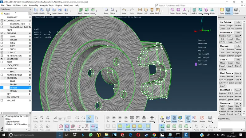
Once the surface mesh is done we can follow the similar process for obtaining the tetra mesh & dealig with the off elements.
2.Main Hub/Knuckle-
Same procedure will be followed here as its a complex casting component with similar QC.
3.Lower control arm, Steering rack, Anti-roll bar, Link rod, Subframe with all the bushings and mounts-
As these all components has to be meshed with tetra mesh also, we will follow the same procedure. 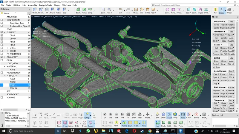
Instead of batch meshing them by selecting all the features in the component in one shot, applying mesh macro area to macro area one by one will allow us to deal with off elemets properly with accurate feature capturing, here we can also choose which feature line to defeature manually on the basis of result obtained. This will give us some flexibility in performing trial and error to obtain optimum results rather than depending solely on automatic algorithm of the software.
After completing the tetra meshing, there were a lot of elements representing kinks and dents on the surface, they have been minimized by using Move free option to move the nodes.
Meshing the uniform thickness components-
In the complete model there are three components with uniform thickness,the shock absorber strut lower body,Control arm connector to the subframe and the link rod bracket mount on the strut.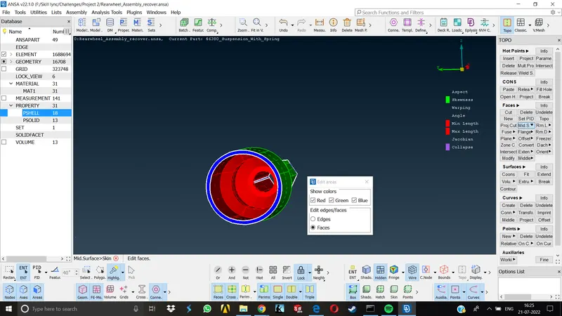
Here, we used the manual offset method to obtain the midsuface of strut body and skin mid method for the bracket for obtaining better results.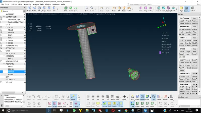
After obtaining the midsurface,we created a new PID for each of them and meshed them with given QC for uniform thickness component.
Connections-
After all the components are meshed acordingly, we can now move on to giving them proper connections
As this is a proper assembly, most of the connections are obviously bolt-on / Nut-bolt connections.
Cluster RBE2 Multinoded connections for representing bolt connections-
All the bolt holes on the components have been given a proper zone-cut for better connectivity of the nodes.
For the bolts which are holding 3 components together, here, On the main hub assembly, the bolts will be holding on to the Wheels as well as brake disc together, cluster Rbe2 has been created on both the ends of the connections and the master nodes have been assigned a two noded connection to represent the stem of the bolt.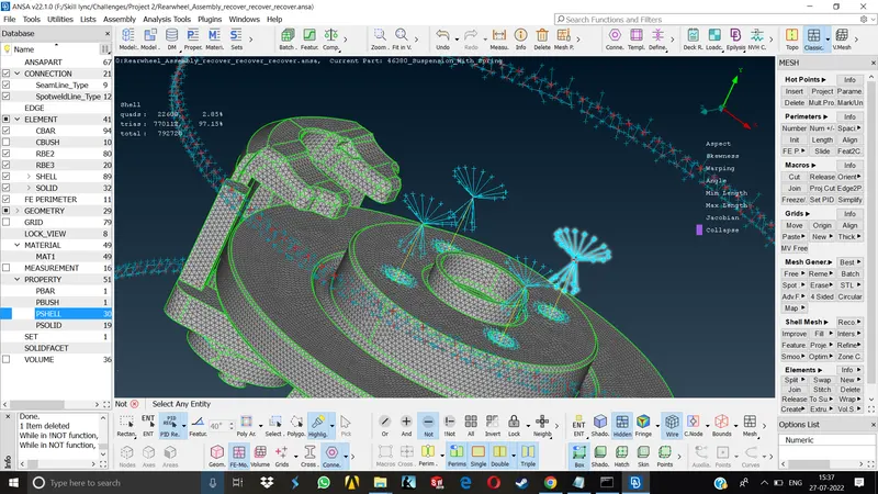
There are some components in the assembly where bolt holes are given on only one component out of two. Specifically the lower control arm connection on the subframe, where the control arm mount is having the bolt hole but the subframe does not have any threaded hole to hold onto the bolt.Here, the nodes in the circular area where the bolt body will be holding the control arm mount have been selected by macro selection and connection has been deployed on the surface area of the subframe body as per the discussion with the support team.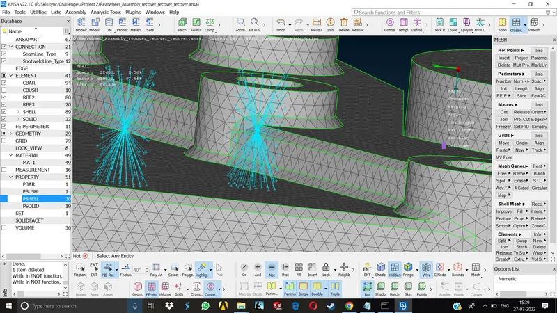
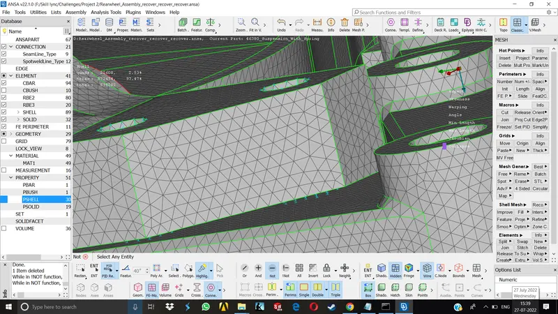
For the ball joints on the steering tie rod, lower control arm ball joint, link rod ball joints, the rod ends are threaded as bolts, they only have a nut connection, for these type of connections, the bolt hole circular cut lines on the mounts are projected on the rod ends and these projected nodes have been assigned a RBE2 many noded connection with the mounts.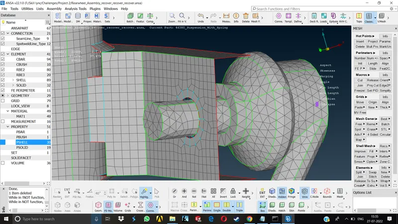
Overlap Shell Connection for connecting components with seam weld-
For the components not consisting of bolt connection in this case such as the link rod mount bracket on the shock absorber strut, we have to use seam weld connection.
Representing the spring as 1D Bar (PBAR) Element-
As suggested in the challenge, the spring has been represented as 1D bar element. We first need to obtain a middle curve of the spring, then create a point on COG of that curve,by going to nastran deck, select these cog point and the curve, assign property to them and then by going to presentation parameters we have to turn on the line element cross sections as solids to be able to see it as solids.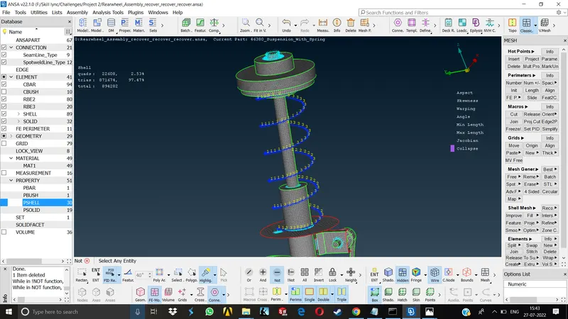
After the PBAR element is formed, we have to connect the nodes of this PBAR element to the holding members of the spring. As the spring is separate component & its held between 2 ends of the shock absorber strut & it doesnt have bolt or seam connection.
CBUSH Connection For connecting Tyre with the rim-
As the tyre is held on to the rim by the pressure of air inside acting on the Beads of the tyre forcing them to stick to the beads on the Rim, this becomes a bush type connection which ideally needs to be represented as a RBE3-CBUSH-RBE3 connection.
For creating this connection, we first need to create curves along with the beads of both the rim and the tyre.
Then convert these curves to spot line and then assign the connection by going to the connection manager and selecting the P1&P2 as tyre and rim.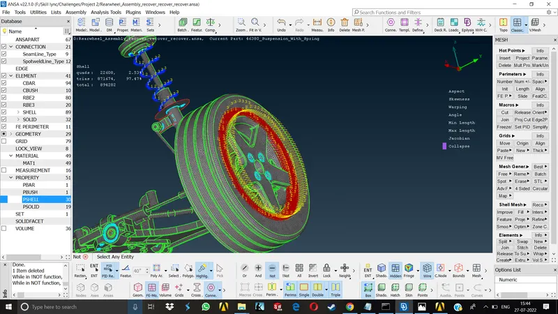
After the CBUSH elements are created we need to match the vector direction of these cbush elements with the global co-ordinates of the assembly to eliminate any kind of deviations in the solving phase.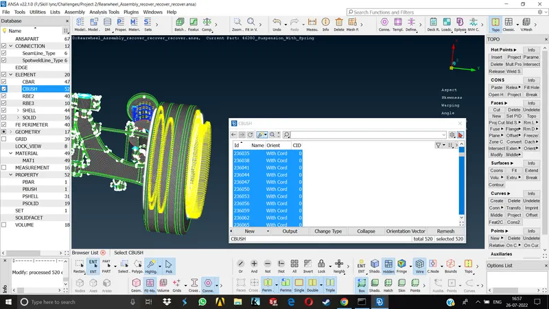
Once all the connections are done, the given geometry has been mirrored by selecting the symmetry & 3 point plane on the one end.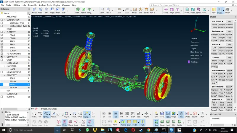
Learning Outcomes-
1.Disintegrating the given assembly in no. of components by PID selection, then working on them one by one.
Previously i used to select them by Macro area to macro area, which would take a long time separating different components.
2.The correct approach to begin with a complex assembly.
3.Representing given component in PBAR elements and assigning proper connection for the same.
4.Giving proper connections by using macro area selection.
5.Giving proper connections to the rod ends, Tyre and rims.
Conclusion-
This project has given me the confidence to work on complex geometries as well as assemblies.
NOTE-Unable to upload the model on the page so attaching google drive link
https://drive.google.com/file/d/1Ss7BkeYNplx3XGIWPuxFaBMO-KcAZJiL/view?usp=sharing